EP1275760A2 - Weft conveying nozzle in an air jet loom - Google Patents
Weft conveying nozzle in an air jet loom Download PDFInfo
- Publication number
- EP1275760A2 EP1275760A2 EP02014943A EP02014943A EP1275760A2 EP 1275760 A2 EP1275760 A2 EP 1275760A2 EP 02014943 A EP02014943 A EP 02014943A EP 02014943 A EP02014943 A EP 02014943A EP 1275760 A2 EP1275760 A2 EP 1275760A2
- Authority
- EP
- European Patent Office
- Prior art keywords
- weft
- passage
- thread guide
- deflective
- air flow
- Prior art date
- Legal status (The legal status is an assumption and is not a legal conclusion. Google has not performed a legal analysis and makes no representation as to the accuracy of the status listed.)
- Granted
Links
Images



Classifications
-
- D—TEXTILES; PAPER
- D03—WEAVING
- D03D—WOVEN FABRICS; METHODS OF WEAVING; LOOMS
- D03D47/00—Looms in which bulk supply of weft does not pass through shed, e.g. shuttleless looms, gripper shuttle looms, dummy shuttle looms
- D03D47/28—Looms in which bulk supply of weft does not pass through shed, e.g. shuttleless looms, gripper shuttle looms, dummy shuttle looms wherein the weft itself is projected into the shed
- D03D47/30—Looms in which bulk supply of weft does not pass through shed, e.g. shuttleless looms, gripper shuttle looms, dummy shuttle looms wherein the weft itself is projected into the shed by gas jet
- D03D47/3006—Construction of the nozzles
- D03D47/3013—Main nozzles
Definitions
- the present invention relates to a weft conveying nozzle in an air jet loom.
- a weft is stored for length measurement in a weft length measurement storage device, and the stored weft is drawn out from the weft length measurement storage device by the air jet action of a weft inserting main nozzle before effecting weft insertion.
- To attain an increase in speed which is an advantage of an air jet loom, it is necessary to increase the speed at which weft insertion is performed. To achieve this, it is necessary to draw out the weft from the weft length measurement storage device within a limited period of time.
- a plurality of cutouts are provided at the forward end of a thread guide to avoid rapid expansion of an air flow in a pipe in which the air flow is mixed with a weft.
- the purpose of avoiding rapid expansion of the air flow in the mixing pipe is to prevent generation of a turbulent flow. Preventing generation of the turbulent flow contributes to increasing weft inserting speed.
- the flow velocity of the air directly in front of the outlet of the thread guide is minimum in the vicinity of an extension of a center axis line of the weft passage in the thread guide.
- the weft flies in the vicinity of the extension of the center axis line of the weft passage. That is, the high velocity portion of the air flow directly in front of the outlet of the thread guide is not effectively utilized in the flying of the weft.
- the plurality of cutouts in the threading nozzle disclosed in Japanese Patent Application Laid-Open No. Hei 9-21035 are arranged circumferentially and in bilateral symmetry.
- the air flowing into the weft passage in the thread guide from the cutouts is bilaterally symmetrical.
- the bilateral symmetry of the air flow entering from the cutouts into the weft passage makes the portion in the vicinity of the extension of the center axis line of the weft passage in the thread guide a minimum velocity air flow portion.
- a substantial increase in the weft inserting speed is not to be expected.
- a weft conveying nozzle including a weft passage into which a weft is introduced and guided, and an air flow passage causing air to flow toward the weft passage along an outer peripheral surface of a thread guide, which forms the weft passage, the air flow passage being extended to a weft route in front of the weft passage to overlap the same, in which the weft passage in the thread guide has a circular sectional configuration, and in which a unitary deflective inflow portion for making an area of the outlet of the weft passage in the thread guide larger than the area of the circular cross-section of the weft passage is formed by cutting the weft passage away from the outlet side toward the weft passage inlet side.
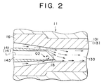
- the existence of the deflective inflow portion shifts, directly in front of the outlet of the thread guide, the minimum velocity portion of the air flow from the vicinity of an extension of a center axis line of the weft passage. That is, directly in front of the outlet of the thread guide, the high velocity portion of the air flow enters the vicinity of the extension of the center axis line of the weft passage, and the high velocity portion of the air flow directly in front of the outlet of the thread guide is effectively utilized in the flying of the weft.
- the diameter of the weft passage in the thread guide for passing the weft is very small.
- a very sophisticated machining technique is required.
- the formation of a unitary deflective inflow portion by cutting can be effected relatively easily.
- a weft conveying nozzle 11 is composed of a cylindrical nozzle body 12, an accelerating tube 13 fitted into the nozzle body 12, a cylindrical thread guide 14 threadely engaged with the nozzle body 12, and a lock nut 15 for fastening the thread guide 14 to the nozzle body 12.
- the forward end portion of the thread guide 14 is formed as a conical flow passage forming portion 141, and, in the middle of the flow passage forming portion 141, a plurality of positioning fins 142 are arranged circumferentially. The tips of the positioning fins 142 are in contact with the inner peripheral surface of the nozzle body 12.
- the accelerating tube 13 is composed of a base tube 131 fitted into the nozzle body 12 and a thin tube 132 fitted into the base tube 131.
- the forward end portion of the flow passage forming portion 141 of the thread guide 14 enters in the base tube 131.
- An annular air flow passage 16 is formed between the outer peripheral surface of the forward end portion of the flow passage forming portion 141 of the thread guide 14 and the tapered inner peripheral surface of the base tube 131.
- a connection port 121 is formed in the nozzle body 12 so as to communicate with the interior of the nozzle body 12, and an air supply pipe 17 is connected to the connection port 121.
- the air supplied from the air supply pipe 17 flows through the air flow passage 16, the base tube 131, and the thin tube 132.
- a weft Y is passed through a weft passage 143 of the thread guide 14 and a traction passage 133 in the accelerating tube 13.
- a deflective inflow portion 18 is formed at the forward end of the flow passage forming portion 141 of the thread guide 14.
- the deflective inflow portion 18 is formed by cutting the forward end portion of the flow passage forming portion 141 along a plane S that is oblique with respect to the center axis line L of the weft passage 143.
- the deflective inflow portion 18 is arranged in the plane S that is a unitary surface.
- the deflective inflow portion 18 formed by cutting along the plane S is cut from the outlet 144 of the weft passage 143 toward the inlet 145 of the weft passage 143.
- the entire deflective inflow portion 18 is surrounded by the air flow passage 16.
- the weft passage 143 of the thread guide 14 has a circular sectional configuration.
- the area of the deflective inflow portion 18 formed by slicing the weft passage 143 along the plane S (the area of the shaded portion in Fig. 1C) is larger than that of the circular sectional portion of the weft passage 143.
- the weft Y which is passed through the weft passage 143 of the thread guide 14 and the traction passage 133 in the accelerating tube 13, receives a driving force due to the air flow in the traction passage 133 in the accelerating tube 13 in front of the forward end of the thread guide 14.
- the traction passage 133 which constitutes the weft passage in front of the weft passage 143, is connected to the air flow passage 16, and is a region where the weft Y and air flow exist.
- a deflective inflow portion 19 is formed by cutting the forward end portion of the thread guide 14 along the unitary surface S1 so as not to slice the weft passage 143.
- a deflective inflow portion 20 is formed by cutting the forward end portion of the thread guide 14 along a unitary concave surface C1 so as to slice the weft passage 143.
- a deflective inflow portion 21 is formed by cutting the forward end portion of the thread guide 14 along a unitary convex surface C2 so as to slice the weft passage 143.
- Each of the deflective inflow portions 19 through 21 in the second through fourth embodiments is surrounded by the air flow passage 16.
Landscapes
- Engineering & Computer Science (AREA)
- Textile Engineering (AREA)
- Looms (AREA)
Abstract
Description
Claims (5)
- A weft conveying nozzle (11) in an air jet loom, comprising a weft passage (143) into which a weft (Y) is introduced for guidance and an air flow passage (16) for causing air to flow toward said weft passage (143) along an outer peripheral surface of a thread guide (14), which forms said weft passage (143), said air flow passage (16) being extended to a weft route in front of said weft passage (143) to overlap the same,
wherein said weft passage (143) in said thread guide (14) has a circular sectional configuration, and wherein a unitary deflective inflow portion (18, 19, 20, 21) for making an area of the outlet portion of said weft passage (143) in said thread guide (14) larger than that of the circular cross-section is formed by cutting from the outlet (144) side toward the inlet (145) side of said weft passage (143). - A weft conveying nozzle in an air jet loom according to Claim 1, wherein said unitary deflective inflow portion (18, 19, 20, 21) is arranged in a unitary surface.
- A weft conveying nozzle in an air jet loom according to Claim 2, wherein said unitary deflective inflow portion (18, 19, 20, 21) is formed by cutting the forward end portion of said thread guide (14) along a plane (S, S1) obliquely intersecting the center axis line (L) of said weft passage (143).
- A weft conveying nozzle in an air jet loom according to Claim 3, wherein said unitary deflective inflow portion (18, 19, 20, 21) is formed by cutting the forward end portion of said thread guide (14) along said plane (S) so as to slice said weft passage (143).
- A weft conveying nozzle in an air jet loom according to Claim 2, wherein said unitary deflective inflow portion (18, 19, 20, 21) is formed by cutting the forward end portion of said thread guide (14) along a curved surface (C1, C2) obliquely intersecting the center axis line (L) of said weft passage (143).
Applications Claiming Priority (2)
| Application Number | Priority Date | Filing Date | Title |
|---|---|---|---|
| JP2001210823 | 2001-07-11 | ||
| JP2001210823A JP4461650B2 (en) | 2001-07-11 | 2001-07-11 | Weft yarn transfer nozzle in air jet loom |
Publications (3)
| Publication Number | Publication Date |
|---|---|
| EP1275760A2 true EP1275760A2 (en) | 2003-01-15 |
| EP1275760A3 EP1275760A3 (en) | 2004-01-14 |
| EP1275760B1 EP1275760B1 (en) | 2007-01-10 |
Family
ID=19046234
Family Applications (1)
| Application Number | Title | Priority Date | Filing Date |
|---|---|---|---|
| EP20020014943 Expired - Lifetime EP1275760B1 (en) | 2001-07-11 | 2002-07-08 | Weft conveying nozzle in an air jet loom |
Country Status (4)
| Country | Link |
|---|---|
| EP (1) | EP1275760B1 (en) |
| JP (1) | JP4461650B2 (en) |
| CN (1) | CN1229531C (en) |
| DE (1) | DE60217443T2 (en) |
Cited By (3)
| Publication number | Priority date | Publication date | Assignee | Title |
|---|---|---|---|---|
| CN112553752A (en) * | 2020-12-17 | 2021-03-26 | 苏州新东南纺织科技有限公司 | Jet loom nozzle |
| EP4187005A1 (en) * | 2021-11-29 | 2023-05-31 | Kabushiki Kaisha Toyota Jidoshokki | Weft yarn transferring nozzle for air jet loom |
| BE1030570B1 (en) * | 2022-06-15 | 2024-05-15 | Toyota Jidoshokki Kk | NOZZLE FOR TRANSFERRING A WEFT YARN FOR AN AIR JET TYPE WEAVING Loom |
Families Citing this family (3)
| Publication number | Priority date | Publication date | Assignee | Title |
|---|---|---|---|---|
| JP2007308825A (en) * | 2006-05-17 | 2007-11-29 | Toyota Central Res & Dev Lab Inc | Weft insertion device in air jet loom |
| JP2008057070A (en) * | 2006-08-31 | 2008-03-13 | Tsudakoma Corp | Weft insertion nozzle for fluid jet loom |
| CN107986078B (en) * | 2017-11-15 | 2019-10-25 | 李天合 | A kind of counting of printing packaging equipment blows mark and divides stacking device and method |
Family Cites Families (5)
| Publication number | Priority date | Publication date | Assignee | Title |
|---|---|---|---|---|
| CH610366A5 (en) * | 1976-09-27 | 1979-04-12 | Rueti Ag Maschf | Device for inserting weft threads into a shed |
| DE2911862A1 (en) * | 1979-03-13 | 1980-09-25 | Sulzer Ag | NOZZLE ARRANGEMENT FOR A WEAVING MACHINE WITH BEAM ENTRY |
| JPS5771445A (en) * | 1980-10-15 | 1982-05-04 | Nissan Motor | Wefting nozzle of air jet type loom |
| CS249259B1 (en) * | 1983-08-01 | 1987-03-12 | Frantisek Vykydal | Pick insertion device for jet loom |
| DE19511439C1 (en) * | 1995-03-29 | 1996-03-14 | Dornier Gmbh Lindauer | System to increase productivity of jet loom |
-
2001
- 2001-07-11 JP JP2001210823A patent/JP4461650B2/en not_active Expired - Fee Related
-
2002
- 2002-07-08 EP EP20020014943 patent/EP1275760B1/en not_active Expired - Lifetime
- 2002-07-08 DE DE2002617443 patent/DE60217443T2/en not_active Expired - Lifetime
- 2002-07-08 CN CN 02141159 patent/CN1229531C/en not_active Expired - Lifetime
Cited By (4)
| Publication number | Priority date | Publication date | Assignee | Title |
|---|---|---|---|---|
| CN112553752A (en) * | 2020-12-17 | 2021-03-26 | 苏州新东南纺织科技有限公司 | Jet loom nozzle |
| CN112553752B (en) * | 2020-12-17 | 2022-04-26 | 苏州新东南纺织科技有限公司 | Jet loom nozzle |
| EP4187005A1 (en) * | 2021-11-29 | 2023-05-31 | Kabushiki Kaisha Toyota Jidoshokki | Weft yarn transferring nozzle for air jet loom |
| BE1030570B1 (en) * | 2022-06-15 | 2024-05-15 | Toyota Jidoshokki Kk | NOZZLE FOR TRANSFERRING A WEFT YARN FOR AN AIR JET TYPE WEAVING Loom |
Also Published As
| Publication number | Publication date |
|---|---|
| DE60217443T2 (en) | 2007-08-23 |
| EP1275760B1 (en) | 2007-01-10 |
| EP1275760A3 (en) | 2004-01-14 |
| JP2003020543A (en) | 2003-01-24 |
| DE60217443D1 (en) | 2007-02-22 |
| CN1396323A (en) | 2003-02-12 |
| CN1229531C (en) | 2005-11-30 |
| JP4461650B2 (en) | 2010-05-12 |
Similar Documents
| Publication | Publication Date | Title |
|---|---|---|
| EP3000971A1 (en) | Double-jet film cooling structure and method for manufacturing same | |
| EP1275760B1 (en) | Weft conveying nozzle in an air jet loom | |
| US5697405A (en) | Weft thread insertion nozzle | |
| JPS6137376B2 (en) | ||
| JPH0874143A (en) | Modified reed for air jet loom | |
| EP2014808B1 (en) | Weft insertion nozzle | |
| US4480434A (en) | Air nozzle for processing a fiber bundle | |
| JP2007077542A (en) | Weft insertion apparatus in air jet loom | |
| JP2005015923A (en) | Weft insertion nozzle for water jet loom | |
| JP2004156162A (en) | Weft insertion nozzle of air jet loom and pipe for the same | |
| JP6039031B2 (en) | Injection nozzle for water jet loom | |
| JP7750798B2 (en) | Weft transport nozzle for air jet looms | |
| JP2000508391A (en) | Auxiliary blow nozzle for air jet loom | |
| JP3934026B2 (en) | Weft insertion nozzle of fluid jet loom | |
| CN100507112C (en) | Weft insertion nozzles for water jet looms | |
| JPS5852305Y2 (en) | Weft guide in fluid jet looms | |
| JPH1089494A (en) | Steam control valve | |
| JPH08246295A (en) | Weft-insertion nozzle of fluid-jet loom | |
| EP0111906A1 (en) | Weft picking device of air jet type weaving loom | |
| JP2003049342A (en) | Weft insertion nozzle of fluid injection loom | |
| JP2724587B2 (en) | Osa feather for air jet loom and method of manufacturing the same | |
| EP0976856A1 (en) | Yarn treatment jet | |
| EP3640382B1 (en) | Sub-nozzle for air jet loom | |
| CN115522304B (en) | A main nozzle for accelerating jet looms | |
| JP7311297B2 (en) | Sub-nozzle of air jet loom |
Legal Events
| Date | Code | Title | Description |
|---|---|---|---|
| PUAI | Public reference made under article 153(3) epc to a published international application that has entered the european phase |
Free format text: ORIGINAL CODE: 0009012 |
|
| 17P | Request for examination filed |
Effective date: 20020708 |
|
| AK | Designated contracting states |
Kind code of ref document: A2 Designated state(s): AT BE BG CH CY CZ DE DK EE ES FI FR GB GR IE IT LI LU MC NL PT SE SK TR |
|
| AX | Request for extension of the european patent |
Free format text: AL;LT;LV;MK;RO;SI |
|
| PUAL | Search report despatched |
Free format text: ORIGINAL CODE: 0009013 |
|
| AK | Designated contracting states |
Kind code of ref document: A3 Designated state(s): AT BE BG CH CY CZ DE DK EE ES FI FR GB GR IE IT LI LU MC NL PT SE SK TR |
|
| AX | Request for extension of the european patent |
Extension state: AL LT LV MK RO SI |
|
| AKX | Designation fees paid |
Designated state(s): BE DE IT |
|
| GRAP | Despatch of communication of intention to grant a patent |
Free format text: ORIGINAL CODE: EPIDOSNIGR1 |
|
| GRAS | Grant fee paid |
Free format text: ORIGINAL CODE: EPIDOSNIGR3 |
|
| GRAA | (expected) grant |
Free format text: ORIGINAL CODE: 0009210 |
|
| AK | Designated contracting states |
Kind code of ref document: B1 Designated state(s): BE DE IT |
|
| REF | Corresponds to: |
Ref document number: 60217443 Country of ref document: DE Date of ref document: 20070222 Kind code of ref document: P |
|
| PLBE | No opposition filed within time limit |
Free format text: ORIGINAL CODE: 0009261 |
|
| STAA | Information on the status of an ep patent application or granted ep patent |
Free format text: STATUS: NO OPPOSITION FILED WITHIN TIME LIMIT |
|
| 26N | No opposition filed |
Effective date: 20071011 |
|
| PGFP | Annual fee paid to national office [announced via postgrant information from national office to epo] |
Ref country code: IT Payment date: 20210610 Year of fee payment: 20 |
|
| PGFP | Annual fee paid to national office [announced via postgrant information from national office to epo] |
Ref country code: BE Payment date: 20210617 Year of fee payment: 20 |
|
| PGFP | Annual fee paid to national office [announced via postgrant information from national office to epo] |
Ref country code: DE Payment date: 20210608 Year of fee payment: 20 |
|
| REG | Reference to a national code |
Ref country code: DE Ref legal event code: R071 Ref document number: 60217443 Country of ref document: DE |
|
| REG | Reference to a national code |
Ref country code: BE Ref legal event code: MK Effective date: 20220708 |