JP3934026B2 - Weft insertion nozzle of fluid jet loom - Google Patents
Weft insertion nozzle of fluid jet loom Download PDFInfo
- Publication number
- JP3934026B2 JP3934026B2 JP2002304932A JP2002304932A JP3934026B2 JP 3934026 B2 JP3934026 B2 JP 3934026B2 JP 2002304932 A JP2002304932 A JP 2002304932A JP 2002304932 A JP2002304932 A JP 2002304932A JP 3934026 B2 JP3934026 B2 JP 3934026B2
- Authority
- JP
- Japan
- Prior art keywords
- rectifying
- rectification
- needle
- water supply
- rectifying member
- Prior art date
- Legal status (The legal status is an assumption and is not a legal conclusion. Google has not performed a legal analysis and makes no representation as to the accuracy of the status listed.)
- Expired - Fee Related
Links
- 239000012530 fluid Substances 0.000 title claims description 23
- 238000003780 insertion Methods 0.000 title claims description 14
- 230000037431 insertion Effects 0.000 title claims description 14
- XLYOFNOQVPJJNP-UHFFFAOYSA-N water Substances O XLYOFNOQVPJJNP-UHFFFAOYSA-N 0.000 claims description 46
- 230000002093 peripheral effect Effects 0.000 claims description 17
- 230000000149 penetrating effect Effects 0.000 claims description 4
- 238000002347 injection Methods 0.000 description 10
- 239000007924 injection Substances 0.000 description 10
- 238000011144 upstream manufacturing Methods 0.000 description 10
- 229920004482 WACKER® Polymers 0.000 description 4
- 238000009792 diffusion process Methods 0.000 description 3
- 230000000694 effects Effects 0.000 description 3
- 239000004744 fabric Substances 0.000 description 3
- 238000012986 modification Methods 0.000 description 3
- 230000004048 modification Effects 0.000 description 3
- 230000007547 defect Effects 0.000 description 2
- 235000012489 doughnuts Nutrition 0.000 description 2
- 229920000728 polyester Polymers 0.000 description 2
- 239000004677 Nylon Substances 0.000 description 1
- 238000013459 approach Methods 0.000 description 1
- 230000007423 decrease Effects 0.000 description 1
- 238000004519 manufacturing process Methods 0.000 description 1
- 229920001778 nylon Polymers 0.000 description 1
- 239000002759 woven fabric Substances 0.000 description 1
Images


Classifications
-
- D—TEXTILES; PAPER
- D03—WEAVING
- D03D—WOVEN FABRICS; METHODS OF WEAVING; LOOMS
- D03D47/00—Looms in which bulk supply of weft does not pass through shed, e.g. shuttleless looms, gripper shuttle looms, dummy shuttle looms
- D03D47/28—Looms in which bulk supply of weft does not pass through shed, e.g. shuttleless looms, gripper shuttle looms, dummy shuttle looms wherein the weft itself is projected into the shed
- D03D47/32—Looms in which bulk supply of weft does not pass through shed, e.g. shuttleless looms, gripper shuttle looms, dummy shuttle looms wherein the weft itself is projected into the shed by liquid jet
-
- B—PERFORMING OPERATIONS; TRANSPORTING
- B05—SPRAYING OR ATOMISING IN GENERAL; APPLYING FLUENT MATERIALS TO SURFACES, IN GENERAL
- B05B—SPRAYING APPARATUS; ATOMISING APPARATUS; NOZZLES
- B05B1/00—Nozzles, spray heads or other outlets, with or without auxiliary devices such as valves, heating means
- B05B1/02—Nozzles, spray heads or other outlets, with or without auxiliary devices such as valves, heating means designed to produce a jet, spray, or other discharge of particular shape or nature, e.g. in single drops, or having an outlet of particular shape
- B05B1/06—Nozzles, spray heads or other outlets, with or without auxiliary devices such as valves, heating means designed to produce a jet, spray, or other discharge of particular shape or nature, e.g. in single drops, or having an outlet of particular shape in annular, tubular or hollow conical form
-
- D—TEXTILES; PAPER
- D03—WEAVING
- D03D—WOVEN FABRICS; METHODS OF WEAVING; LOOMS
- D03D49/00—Details or constructional features not specially adapted for looms of a particular type
- D03D49/24—Mechanisms for inserting shuttle in shed
- D03D49/50—Miscellaneous devices or arrangements concerning insertion of weft and not otherwise provided for
-
- D—TEXTILES; PAPER
- D03—WEAVING
- D03J—AUXILIARY WEAVING APPARATUS; WEAVERS' TOOLS; SHUTTLES
- D03J1/00—Auxiliary apparatus combined with or associated with looms
- D03J1/04—Auxiliary apparatus combined with or associated with looms for treating weft
Landscapes
- Engineering & Computer Science (AREA)
- Textile Engineering (AREA)
- Looms (AREA)
- Knitting Machines (AREA)
Description
【0001】
【発明の属する技術分野】
本発明は、流体噴射式織機の緯入れノズルに関する。
【0002】
【従来の技術】
従来の流体噴射式織機の緯入れノズルとしては、ノズル本体の中にニードルを挿入し、ニードルの先部とノズル本体の間に環状の流路を形成し、その流路に2つの整流部材を配置し、ノズル本体には適切な数の給水孔を流路の上流側に設け、下流側の整流部材とニードルとの間の噴射孔から流体を噴射するものがある。また、整流部材は、全体として円筒状で、放射状の整流フィンを円周方向に等間隔で設け、隣接する整流フィンの間に形成される整流溝に、流体を通過させるもので、上流側の整流部材は、整流フィンの数を16枚とし、下流側の整流部材は、整流フィンの数を18枚としてある(例えば、特許文献1参照。)。
【0003】
【特許文献1】
特開2000−119937号公報(第3頁左欄、第4頁右欄、第5図、第6図)
【0004】
【発明が解決しようとする課題】
ところが、上述した従来のものは、上流側と下流側の整流溝の重なり具合(上流側の整流溝の中心と下流側の整流溝の中心との関係)については考慮してない。整流フィンの数が上流側と下流側の整流部材とで違うと、上流側と下流側の整流溝の重なり具合が、整流溝毎に異なってくる。そうすると、整流溝を通過する流体の流速が整流溝毎に異なって流体にニードルの周りに旋回流を生ずることになる結果、流量の多い部分と少ない部分とが発生して、噴射孔からのジェット流の断面形状が、真円から外れた形状になりやすい。特に、上流側の整流フィンの数と、下流側の整流フィンの数との間に、整数倍以外の公約数が存在する場合は、その傾向が顕著である。例えば、前述したように上流側の整流フィンの数が16で、下流側の整流フィンの数が18で、双方の数の公約数が2である場合に、上流側の整流溝の中心と下流側の整流溝の中心を一致すると、図11に示すように、ジェット流の断面形状は、整流溝の中心の重なり具合が最も大きい位置で最も膨らむ、すなわち二方向に突出した扁平な形状となるものと予想される。ジェット流がこのように真円から外れた形状になると、拡散が大きくなったり、あるいは経糸開口に衝突して織物欠点(縦筋)が生ずるという問題がある。
【0005】
また、上述した従来のものは、上流側と下流側の整流フィン同士の間の隙間寸法、給水孔の数と整流溝の数の関係や、給水孔と整流溝との連通具合(給水孔の中心と整流溝の中心との関係)についても何等述べていない。しかし、これらも上述した問題を生ずる要因となるものである。
【0006】
そこで、本発明の解決課題は、複数の整流部材の整流溝の数の最適化を図りつつ、併せて上流側と下流側の整流フィン同士の間の隙間寸法、給水孔の数と整流溝の数の各関係についても最適化を図ることである。
【0007】
【課題を解決するための手段】
請求項1に係る発明は、導糸孔を有するニードルと、中空状に形成され、中空部に貫通する給水孔を備える一方、中空部にニードルが挿入されてニードルとの間に、給水孔に通じる環状の流路を構成するノズル本体と、緯糸進行方向に順番に環状の流路に配置される複数の整流部材とからなり、各整流部材は、その円周方向に等間隔に設けられ且つニードルの外周面又はノズル本体の内周面から他方の側及び軸方向にそれぞれ延在する複数の整流フィンを有すると共に、隣接する整流フィンにより画定される整流溝を整流路として有する、流体噴射式織機の緯入れノズルにおいて、第一整流部材と第二整流部材の各整流路の数を、6以上40以下とし、且つ、第二整流部材の整流路の数を、第一整流部材の整流路の数に対してK倍あるいは1/K倍(Kは2以上の整数)の整数に定め、第一整流部材の整流路又は整流フィンの中心と、第二整流部材の整流路又は整流フィンの中心とが一致した状態で第一及び第二整流部材を配置すると共に、上記第一及び第二整流部材の配置状態を確定するための係合部を、第一整流部材と第二整流部材との間に形成する、ことを特徴とする。
【0008】
請求項2に係る発明は、導糸孔を有するニードルと、中空状に形成され、中空部に貫通する給水孔を備える一方、中空部にニードルが挿入されてニードルとの間に給水孔に通じる環状の流路を構成するノズル本体と、緯糸進行方向に順番に環状の流路に配置される複数の整流部材とからなり、第一整流部材は、円周方向に等間隔に且つ軸方向に延在すべく設けられる整流孔を整流路として有し、第二整流部材は、円周方向に等間隔に設けられ且つニードルの外周面又はノズル本体から他方の側および軸方向にそれぞれ延在する複数の整流フィンを有すると共に、隣接する整流フィンにより画定される整流溝を整流路として有する、流体噴射式織機の緯入れノズルにおいて、第一整流部材と第二整流部材の各整流路の数を、6以上40以下とし、且つ、第二整流部材の整流路の数を、第一整流部材の整流路の数に対してK倍あるいは1/K倍(Kは2以上の整数)の整数に定め、第一整流部材の整流孔の中心と、第二整流部材の整流溝又は整流フィンの中心とが一致した状態で第一及び第二整流部材を配置すると共に、上記第一及び第二整流部材の配置状態を確定するための係合部を、第一整流部材と第二整流部材との間に形成する、ことを特徴とする。
【0030】
【発明の実施の形態】
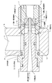
流体噴射式織機の緯入れノズルは図1に示すように、ニードル1をノズル本体2の中空部3に挿入し、ニードル1の先部とノズル本体2の間に環状の流路を形成し、その流路の後部を環状室4とし、その流路の先部に第一、第二整流部材5、6を圧入して緯糸進行方向に順番に配置し、第一、第二整流部材5,6とニードル1との間に流路を形成し、ニードル1と第二整流部材6の先端との間に流体の噴射孔7を形成してある。筒状をなすノズルホルダー8の先部の挿入孔9にノズル本体2を通し、ノズル本体2の先部外側にノズルキャップ10をねじこんでノズルホルダー8にノズル本体2を固定し、ノズルホルダー8内の送水路11に連通する環状溝12を、ノズル本体2の外周面に形成し、環状溝12と環状室4を連通する複数の給水孔13を、ノズル本体2の円周方向に等間隔で傾斜して形成してある。
【0031】
ニードル1は、導糸孔14をその軸線方向に貫通しており、環状の流路に面する外径部分を段差状に細くし且つ先細り形状とし、その先端部を噴射孔7よりも突出させてある。また、ニードル1は、その基部側をノズル本体2にネジで連結し、ネジでの連結部分と環状室4との間の部分では、ノズル本体2の内面とOリングでシールしてある。
【0032】
ノズル本体2は、噴射孔7よりも先端側の内径を段差状に狭くすることによって、第二整流部材5を環状室4から脱出不能に収容する。ノズル本体2は、ノズルホルダー8の挿入孔9との間をOリングでシールしてある。また、ノズルキャップ10の端面とノズルホルダー8の挿入孔9の近傍とノズル本体2をOリングでシールしてある。
【0033】
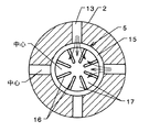
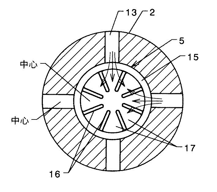
第一整流部材5は図1又は図2に示すように、環状室4よりも緯糸進行方向側に配置されており、円筒状のワッカ15の内側に整流フィン16を円周方向に沿って等間隔をあけて複数設けてある。整流フィン16は、ニードル1の軸線を中心とする放射方向については、ワッカ15の内周面からニードル1の外周面に達する手前まで延長し、整流フィン16とニードル1の外周面との間に間隔をあけ、軸線方向については、ワッカ15の環状室4側の端面から第二整流部材6側の端面の手前まで延長してある。隣接する整流フィン16,16の間を整流路としての整流溝17とし、整流溝17内に流体を通過させると共に、整流フィン16とニードル1の外周面との間隔にも流体を通過させる。
【0034】
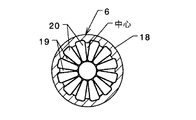
第二整流部材6は図1又は図2に示すように、ワッカ18の内周面を噴射孔7に向かって径が小さくなるテーパ状に形成し、ワッカ18の内側に整流フィン19を円周方向に沿って等間隔をあけて複数設けてある。テーパー状のワッカ18の内周面は、噴射孔7の手前までは急な勾配で、その後は緩やかな勾配としてある。その整流フィン19は、ニードル1の軸線を中心とする放射方向については、ワッカ18の内周面からニードル1の外周面に達する手前まで延長し、整流フィン19とニードル1の外周面との間に間隔をあけると共に、軸線方向については、噴射孔7に近づくにつれて放射方向の幅が狭くなる三角形状で、第一整流部材5側の端面からテーパーの勾配が変わる境目まで延長してある。また、隣接する整流フィン19,19の間に整流溝20を設けてある。
【0035】
図1に示すように、第一整流部材5の整流フィン16と第二整流部材6の整流フィン19との間には隙間21をあけてある。隙間21は、0.1mm以上数mm以下とする。
【0036】
図2には、第一整流部材5の整流溝17の数と第二整流部材6の整流溝20の数を、6以上40以下で且つ互いに公約数を有しない数とし、給水孔13の数を4以上26以下にし、第一整流部材5の整流溝17の数を給水孔13の数の1.5倍以上の数とし、且つ給水孔13の数と第一整流部材5の整流溝17を互いに公約数を有しない数とした一例が示してある。図面では、給水孔13の数が7、第一整流部材5の整流溝17の数が15、第二整流部材6の整流溝20の数が17としてある。
【0037】
また、上述した条件を満足する給水孔13の数と第一整流部材5の整流溝17の数との関係が表1には具体的に示してある。なお、給水孔13の数が13以上26以下のときの第一整流部材5の整流溝17の数との関係は、データが膨大になるので省略してある。給水孔13の数が6のときの第一整流部材5の整流溝17の数と第二整流部材6の整流溝20の数との関係が表2に示してある。なお、給水孔13の数が6以外の数のときの、第一整流部材5の整流溝17の数と第二整流部材6の整流溝20の数との関係は、データが膨大になるので省略してある。
【0038】
【表1】
【表2】
給水孔13の数と第一整流部材5の整流溝17の数との関係は、給水孔13の数が6から12で、第一整流部材5の整流溝17の数が12から36の範囲が望ましい。また、第一整流部材5の整流溝17の数と第二整流部材6の整流溝20の数を15から35の範囲にすることが望ましい。第二整流部材6の整流溝20の数を、給水孔13の数と、第一整流部材5の整流溝17の数よりも多くすることが、整流効果を高める上で望ましい。第二整流部材6の整流溝20の数を第一整流部材5の整流溝17の数の近くの数にすると、乱流が生じにくくなる効果が向上する。
【0041】
図3には、給水孔13の数を4以上12以下とする一方、第一整流部材5の整流溝17の数を、給水孔13の数の1倍以上の整数倍の数とし、且つ給水孔13の中心と第一整流部材5の整流溝17の中心を一致した一例が示してある。図面では、給水孔13の数を4に、第一整流部材5の整流溝17の数を8にして、2倍にしてある。
【0042】
第一整流部材5の8つの整流溝17のうち4つの中心を、給水孔13の中心と一致してあるので、給水孔13からその4つの整流溝17には、流体が真っ直ぐ流れ込む。一方、整流溝17のうち残りの4つは、隣接する2つの給水孔13と同じ距離(角度)となるので、2つの給水孔13から各整流溝17に均等に流体が流れ込む。従って、流体の旋回流の発生が抑制され、噴射孔7からのジェット流の拡散を抑えられる。
【0043】
図3に対し、給水孔13の中心と第一整流部材5の整流フィン16の中心とを一致させるように配置することも考えられる。つまり、ワッカ15を軸心を中心に約22.5°回転されたものを想定したとき、第一整流部材5の8つの整流フィン16のうち4つの中心を、給水孔13の中心と一致するように配置されるため、給水孔13からの流体が整流フィン16により左右に分かれ、隣接する2つの整流溝17に均等に流れ込む。従って、流体の旋回流が抑制され、噴射孔7からのジェット流の拡散が抑えられる。
【0044】
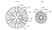
図4には、第一整流部材5と第二整流部材6の各整流溝17,20の数を6以上40以下で、且つ第二整流部材6の整流溝20の数を第一整流部材5の整流溝17の数に対してK倍あるいは1/K倍の整数に定めると共に、Kは2以上の整数とし、第一整流部材5の整流溝17の中心あるいは整流フィン16の中心のいずれかと、第二整流部材6の整流溝20あるいは整流フィン19のいずれかの中心とが一致する一例を示してある。図面では、第一整流部材5の整流溝17の数を6とし、第二整流部材6の整流溝20の数を12とし、第一整流部材5の整流フィン19の中心と、第二整流部材6の整流溝20の中心を一致してある。
【0045】
図4で示した第二整流部材6を、軸線を中心として15度回転させると、図5に示すように、第一整流部材5の整流フィン16の中心と、第二整流部材6の整流フィン19の中心が一致する。
【0046】
また、上述した第一整流部材5の整流溝17と第二整流部材6の整流溝20の数の条件を満足する関係が表3に示してある。なお、第一整流部材5の整流溝17の数が7以下のときの第一整流部材5の整流溝20の数との関係は省略してある。
【0047】
【表3】
給水孔13の数を4以上26以下とする一方、第一整流部材5の整流溝17の数を給水孔13の数の1倍以上の整数倍の数とするという条件を満足する関係が表4に具体的に示してある。なお、給水孔13の数が13以上26以下のときの第一整流部材5の整流溝17の数との関係は省略してある。
【0049】
【表4】
図6は、ノズル本体2とニードル1のうち整流部材5,6を固定する方と、第一整流部材5と、第二整流部材6の少なくとも2つに係合部22,23をそれぞれ設け、係合部が、給水孔13の中心、第一整流部材5の整流溝17又は整流フィン16の中心、及び第二整流部材6の整流溝20又は整流フィン19の中心のうち2以上を一致させる一例を示したものである。図面では、ノズル本体2に整流部材5,6を固定し、第一整流部材5の整流溝17の中心、第二整流部材6の整流溝20の中心を一致させる係合部22、23を、第一整流部材5と第二整流部材6の突き合わせる端面同士に凹凸形状として設けてある。このような係合部22、23は、給水孔13の中心と第一整流部材5の整流溝17の中心または整流フィン16の中心とを一致するように配置すべく、ノズル本体2の中空部3の内周面と第一整流部材5の外周面との間に形成されてもよい。また、前者と後者を同時に設けることも考えられる。
【0051】
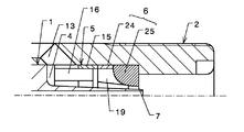
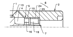
第二整流部材6の形状は、前述した形状に限られず、図7に示すように、整流溝17を、軸線方向については噴射孔7まで延長したものでも良い。また、図8に示すように、整流フィン19を設ける部品24と、断面円弧状のオリフィスからなる部品25との二部品から構成しても良い。さらに、図9に示すように、整流フィン19を設ける部品24と、噴射孔7を有する単なるドーナツ板からなる部品25との二部品から構成しても良い。また、第一整流部材5の形状も、前述した形状に限られず、図8に示すように、整流フィン16を軸線方向については環状室4に突入するまで延長しても良い。なお、上記した第一整流部材5の整流溝17を、整流孔に置き換えることも可能である。より具体的には、図12に示すように、ドーナツ状に形成されノズル本体2とニードル1との間に設けられる第一整流部材5に、円周方向に等間隔に丸孔または角孔により形成される整流孔30を設けることが考えられる。この場合、上記した整流溝の数は、整流孔の数に読み替えればよい。さらには、ノズル本体2をノズルホルダー8と別体に設けているが、一体に設けてもよい。
【0052】
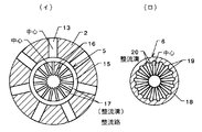
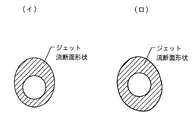
図10の(イ)は、第一整流部材5の整流溝17の数を16、第二整流部材6の整流溝20の数を17とした場合に予想されるジェット流の断面形状を示し、図10の(ロ)は、第一整流部材5の整流溝17の数を15、第二整流部材6の整流溝20の数を17とした場合に予想されるジェット流の断面形状を示しており、何れも真円に近い形状となっていることが理解できる。
【0053】
各種部材の数や中心の位置合わせに関する実験結果が、表5に示してある。実験の織機条件は、織物通し幅:1780mm、織物:ポリエステルタフタ、緯糸:ナイロン70d(デニール)/ポリエステル75d、ポンプからの供給圧力100kgf/cm2、使用水量2.2cc/pickである。
【0054】
【表5】
この表5からは以下のことが把握できる。整流フィン16,19の数を増やしても、織物に縦筋が付くことを改善できない。給水孔13の中心と第一整流部材5の中心の位置合わせ、第一整流部材5の整流溝17の中心と第二整流部材6の整流溝20の中心の位置合わせが、品位を改善するポイントとなる。
【0056】
【発明の効果】
本発明のようにすれば、ニードルとノズル本体の間から噴射されるジェット流の断面形状が、従来よりも真円に近い形状になり、経糸開口に衝突し難くなり、織物欠点(縦筋)を効果的に防止できる。
【図面の簡単な説明】
【図1】流体噴射式織機の緯入れノズルの構造を示す断面図である。
【図2】(イ)(ロ)図1のA−A線断面図、図1のB−B線断面図である。
【図3】給水孔数が4、第一整流部材の整流溝数が8の例を示す断面図である。
【図4】(イ)(ロ)(イ)図は、給水孔数が6、第一整流部材の整流溝数が6の例を示す断面図、、(ロ)図は、そのときの第二整流部材の整流溝数が12の例を示す断面図である。
【図5】図4(ロ)の整流溝を15度回転させた状態を示す断面図である。
【図6】第一整流部材と第二整流部材の係合部を示す断面図である。
【図7】第二整流部材の変形例を示す断面図である。
【図8】第一整流部材と第二整流部材の変形例を示す断面図である。
【図9】第二整流部材の変形例を示す断面図である。
【図10】(イ)(ロ)異なる条件でのジェット流の断面形状を示す一例である。
【図11】従来のジェット流の断面形状を示す一例である。
【図12】第一整流部材の整流路を整流孔で形成した例を示す断面図である。
【符号の説明】
1 ニードル
2 ノズル本体
3 中空部
5 第一整流部材
6 第二整流部材
13 給水孔
14 導糸孔
16、19 整流フィン
17、20、30 整流路(整流溝、整流孔)
21 隙間
22、23 係合部[0001]
BACKGROUND OF THE INVENTION
The present invention relates to a weft insertion nozzle for a fluid jet loom.
[0002]
[Prior art]
As a weft insertion nozzle of a conventional fluid jet loom, a needle is inserted into a nozzle body, an annular channel is formed between the tip of the needle and the nozzle body, and two rectifying members are provided in the channel. Some nozzle bodies are provided with an appropriate number of water supply holes on the upstream side of the flow path, and fluid is ejected from the ejection holes between the rectifying member and the needle on the downstream side. The rectifying member has a cylindrical shape as a whole, and radial rectifying fins are provided at equal intervals in the circumferential direction to allow fluid to pass through rectifying grooves formed between adjacent rectifying fins. The rectifying member has 16 rectifying fins, and the downstream rectifying member has 18 rectifying fins (see, for example, Patent Document 1).
[0003]
[Patent Document 1]
Japanese Unexamined Patent Publication No. 2000-119937 (page 3, left column,
[0004]
[Problems to be solved by the invention]
However, the above-described conventional one does not consider the overlapping state of the upstream and downstream rectification grooves (the relationship between the center of the upstream rectification groove and the center of the downstream rectification groove). If the number of rectifying fins is different between the upstream and downstream rectifying members, the degree of overlap between the upstream and downstream rectifying grooves differs for each rectifying groove. Then, the flow velocity of the fluid passing through the rectifying groove is different for each rectifying groove, and as a result, a swirl flow is generated around the needle in the fluid. As a result, a portion with a high flow rate and a portion with a small flow rate are generated. The cross-sectional shape of the flow tends to be out of the perfect circle. In particular, when a common divisor other than an integer multiple exists between the number of upstream rectifying fins and the number of downstream rectifying fins, the tendency is remarkable. For example, as described above, when the number of rectifying fins on the upstream side is 16, the number of rectifying fins on the downstream side is 18, and the common divisor of both numbers is 2, the center of the rectifying groove on the upstream side and the downstream side When the centers of the rectifying grooves on the side coincide with each other, as shown in FIG. 11, the cross-sectional shape of the jet flow swells most at the position where the overlapping state of the rectifying grooves is the largest, that is, a flat shape protruding in two directions. Expected. When the jet flow is in a shape deviating from a perfect circle in this way, there is a problem that diffusion becomes large or a fabric defect (longitudinal streak) occurs due to collision with the warp opening.
[0005]
In addition, the above-mentioned conventional ones have a gap dimension between the upstream and downstream flow straightening fins, the relationship between the number of water supply holes and the number of flow straightening grooves, and the degree of communication between the water supply holes and the flow straightening grooves (of the water supply holes). There is no mention of the relationship between the center and the center of the rectifying groove. However, these are also factors that cause the above-described problems.
[0006]
Accordingly, the problem to be solved by the present invention is to optimize the number of rectifying grooves of a plurality of rectifying members, and at the same time, the gap size between the rectifying fins on the upstream side and the downstream side, the number of water supply holes and the number of rectifying grooves It is to optimize each number relation.
[0007]
[Means for Solving the Problems]
The invention according to
[0008]
The invention according to
[0030]
DETAILED DESCRIPTION OF THE INVENTION
As shown in FIG. 1, the weft insertion nozzle of the fluid jet loom inserts the
[0031]
The
[0032]
The
[0033]
As shown in FIG. 1 or FIG. 2, the first rectifying
[0034]
As shown in FIG. 1 or FIG. 2, the second rectifying
[0035]
As shown in FIG. 1, a
[0036]
In FIG. 2, the number of the rectifying
[0037]
Table 1 specifically shows the relationship between the number of water supply holes 13 that satisfy the above-described conditions and the number of rectifying
[0038]
[Table 1]
[Table 2]
The relationship between the number of water supply holes 13 and the number of rectifying
[0041]
In FIG. 3, the number of the water supply holes 13 is 4 or more and 12 or less, while the number of the rectifying
[0042]
Since four centers of the eight rectifying
[0043]
With respect to FIG. 3, it is also conceivable that the center of the
[0044]
In FIG. 4, the number of the rectifying
[0045]
When the
[0046]
Table 3 shows a relationship that satisfies the conditions of the number of the rectifying
[0047]
[Table 3]
The relationship satisfying the condition that the number of the water supply holes 13 is 4 or more and 26 or less, while the number of the rectifying
[0049]
[Table 4]
FIG. 6 is a perspective view of the
[0051]
The shape of the
[0052]
FIG. 10A shows the cross-sectional shape of the jet flow expected when the number of the rectifying
[0053]
Table 5 shows the experimental results regarding the number of various members and the alignment of the center. The experimental loom conditions were as follows: woven threading width: 1780 mm, woven fabric: polyester taffeta, weft: nylon 70d (denier) / polyester 75d, supply pressure from the pump of 100 kgf / cm 2 , and water consumption amount of 2.2 cc / pick.
[0054]
[Table 5]
From Table 5, the following can be grasped. Even if the number of rectifying
[0056]
【The invention's effect】
According to the present invention, the cross-sectional shape of the jet flow ejected from between the needle and the nozzle body becomes a shape closer to a perfect circle than before, and it becomes difficult to collide with the warp opening, resulting in a fabric defect (longitudinal streak). Can be effectively prevented.
[Brief description of the drawings]
FIG. 1 is a cross-sectional view showing the structure of a weft insertion nozzle of a fluid jet loom.
2A and 2B are cross-sectional views taken along the line AA in FIG. 1 and the cross-sectional view taken along the line BB in FIG. 1;
FIG. 3 is a cross-sectional view showing an example in which the number of water supply holes is 4 and the number of rectifying grooves of the first rectifying member is 8.
FIGS. 4A and 4B are cross-sectional views showing an example in which the number of water supply holes is 6 and the number of rectifying grooves of the first rectifying member is 6, and FIG. It is sectional drawing which shows the example whose number of the rectification grooves of two rectification | straightening members is 12.
FIG. 5 is a cross-sectional view showing a state in which the rectifying groove of FIG.
FIG. 6 is a cross-sectional view showing an engaging portion between a first rectifying member and a second rectifying member.
FIG. 7 is a cross-sectional view showing a modification of the second rectifying member.
FIG. 8 is a cross-sectional view showing a modification of the first rectifying member and the second rectifying member.
FIG. 9 is a cross-sectional view showing a modification of the second rectifying member.
FIGS. 10A and 10B are examples showing a cross-sectional shape of a jet flow under different conditions.
FIG. 11 is an example showing a cross-sectional shape of a conventional jet flow.
FIG. 12 is a cross-sectional view showing an example in which a rectifying path of a first rectifying member is formed by a rectifying hole.
[Explanation of symbols]
DESCRIPTION OF
21
Claims (2)
中空状に形成され、中空部(3)に貫通する給水孔(13)を備える一方、中空部(3)にニードル(1)が挿入されてニードル(1)との間に、給水孔(13)に通じる環状の流路を構成するノズル本体(2)と、
緯糸進行方向に順番に環状の流路に配置される複数の整流部材(5,6)とからなり、
各整流部材(5,6)は、その円周方向に等間隔に設けられ且つニードル(1)の外周面又はノズル本体(2)の内周面から他方の側及び軸方向にそれぞれ延在する複数の整流フィン(16,19)を有すると共に、隣接する整流フィンにより画定される整流溝(17,20)を整流路(17,20)として有する、
流体噴射式織機の緯入れノズルにおいて、
第一整流部材(5)と第二整流部材(6)の各整流路(17,20)の数を、6以上40以下とし、且つ、第二整流部材(6)の整流路(20)の数を、第一整流部材(5)の整流路(17)の数に対してK倍あるいは1/K倍(Kは2以上の整数)の整数に定め、
第一整流部材の整流路(17)又は整流フィン(16)の中心と、第二整流部材の整流路(20)又は整流フィン(19)の中心とが一致した状態で第一及び第二整流部材(5,6)を配置すると共に、
上記第一及び第二整流部材(5,6)の配置状態を確定するための係合部(22,23)を、第一整流部材(5)と第二整流部材(6)との間に形成する、
ことを特徴とする流体噴射式織機の緯入れノズル。A needle (1) having a yarn introduction hole (14);
While being formed in a hollow shape and provided with a water supply hole (13) penetrating the hollow part (3), the needle (1) is inserted into the hollow part (3) and between the needle (1) and the water supply hole (13 Nozzle body (2) constituting an annular flow path leading to
It consists of a plurality of rectifying members (5, 6) arranged in an annular channel in order in the weft travel direction,
The straightening members (5, 6) are provided at equal intervals in the circumferential direction and extend from the outer peripheral surface of the needle (1) or the inner peripheral surface of the nozzle body (2) to the other side and the axial direction, respectively. A plurality of rectifying fins (16, 19) and a rectifying groove (17, 20) defined by adjacent rectifying fins as a rectifying path (17, 20);
In the weft insertion nozzle of the fluid jet loom,
The number of the rectification paths (17, 20) of the first rectification member (5) and the second rectification member (6) is 6 or more and 40 or less, and the rectification path (20) of the second rectification member (6) The number is set to an integer of K times or 1 / K times (K is an integer of 2 or more) with respect to the number of rectification paths (17) of the first rectification member (5),
The first and second rectifications are performed in a state where the center of the rectification path (17) or the rectification fin (16) of the first rectification member is coincident with the center of the rectification path (20) or the rectification fin (19) of the second rectification member. While arranging the members (5, 6),
The engaging portions (22, 23) for determining the arrangement state of the first and second rectifying members (5, 6) are provided between the first rectifying member (5) and the second rectifying member (6). Form,
A weft insertion nozzle for a fluid jet loom.
中空状に形成され、中空部(3)に貫通する給水孔(13)を備える一方、中空部(3)にニードル(1)が挿入されてニードル(1)との間に給水孔(13)に通じる環状の流路を構成するノズル本体(2)と、
緯糸進行方向に順番に環状の流路に配置される複数の整流部材(5,6)とからなり、
第一整流部材(5)は、円周方向に等間隔に且つ軸方向に延在すべく設けられる整流孔(30)を整流路として有し、
第二整流部材(6)は、円周方向に等間隔に設けられ且つニードル(1)の外周面又はノズル本体(2)から他方の側および軸方向にそれぞれ延在する複数の整流フィン(19)を有すると共に、隣接する整流フィンにより画定される整流溝(20)を整流路(20)として有する、
流体噴射式織機の緯入れノズルにおいて、
第一整流部材(5)と第二整流部材(6)の各整流路(30,20)の数を、6以上40以下とし、且つ、第二整流部材(6)の整流路(20)の数を、第一整流部材(5)の整流路(30)の数に対してK倍あるいは1/K倍(Kは2以上の整数)の整数に定め、
第一整流部材の整流孔(30)の中心と、第二整流部材の整流溝(20)又は整流フィン(19)の中心とが一致した状態で第一及び第二整流部材(5,6)を配置すると共に、
上記第一及び第二整流部材(5,6)の配置状態を確定するための係合部(22,23)を、第一整流部材(5)と第二整流部材(6)との間に形成する、
ことを特徴とする流体噴射式織機の緯入れノズル。A needle (1) having a yarn introduction hole (14);
While being formed in a hollow shape and provided with a water supply hole (13) penetrating the hollow part (3), the needle (1) is inserted into the hollow part (3) and the water supply hole (13) is formed between the needle (1) and the needle (1). A nozzle body (2) constituting an annular flow path leading to
It consists of a plurality of rectifying members (5, 6) arranged in an annular channel in order in the weft travel direction,
The first rectification member (5) has a rectification hole (30) provided to extend in the circumferential direction at equal intervals in the circumferential direction as a rectification path,
The second rectification member (6) is provided with a plurality of rectification fins (19) provided at equal intervals in the circumferential direction and extending from the outer peripheral surface of the needle (1) or the nozzle body (2) to the other side and the axial direction, respectively. ) And a rectifying groove (20) defined by adjacent rectifying fins as a rectifying path (20).
In the weft insertion nozzle of the fluid jet loom,
The number of the rectifying paths (30, 20) of the first rectifying member (5) and the second rectifying member (6) is 6 or more and 40 or less, and the rectifying path (20) of the second rectifying member (6) The number is set to an integer of K times or 1 / K times (K is an integer of 2 or more) with respect to the number of rectification paths (30) of the first rectification member (5),
The first and second rectifying members (5, 6) with the center of the rectifying hole (30) of the first rectifying member and the center of the rectifying groove (20) or the rectifying fin (19) of the second rectifying member aligned. And place
The engaging portions (22, 23) for determining the arrangement state of the first and second rectifying members (5, 6) are provided between the first rectifying member (5) and the second rectifying member (6). Form,
A weft insertion nozzle for a fluid jet loom.
Priority Applications (5)
| Application Number | Priority Date | Filing Date | Title |
|---|---|---|---|
| JP2002304932A JP3934026B2 (en) | 2002-10-18 | 2002-10-18 | Weft insertion nozzle of fluid jet loom |
| TW092127163A TW200406515A (en) | 2002-10-18 | 2003-10-01 | Weft inserting nozzle of fluid jet loom |
| KR1020030070799A KR100996356B1 (en) | 2002-10-18 | 2003-10-11 | Inlet nozzle of a fluid jet loom |
| CN200310119866A CN100582339C (en) | 2002-10-18 | 2003-10-18 | Weft insertion nozzle of fluid jet loom |
| CN2008101762793A CN101440549B (en) | 2002-10-18 | 2003-10-18 | Weft insertion nozzle of fluid injection-type weaving machine |
Applications Claiming Priority (1)
| Application Number | Priority Date | Filing Date | Title |
|---|---|---|---|
| JP2002304932A JP3934026B2 (en) | 2002-10-18 | 2002-10-18 | Weft insertion nozzle of fluid jet loom |
Publications (2)
| Publication Number | Publication Date |
|---|---|
| JP2004137638A JP2004137638A (en) | 2004-05-13 |
| JP3934026B2 true JP3934026B2 (en) | 2007-06-20 |
Family
ID=32452205
Family Applications (1)
| Application Number | Title | Priority Date | Filing Date |
|---|---|---|---|
| JP2002304932A Expired - Fee Related JP3934026B2 (en) | 2002-10-18 | 2002-10-18 | Weft insertion nozzle of fluid jet loom |
Country Status (4)
| Country | Link |
|---|---|
| JP (1) | JP3934026B2 (en) |
| KR (1) | KR100996356B1 (en) |
| CN (2) | CN101440549B (en) |
| TW (1) | TW200406515A (en) |
Families Citing this family (7)
| Publication number | Priority date | Publication date | Assignee | Title |
|---|---|---|---|---|
| KR200458311Y1 (en) * | 2009-12-24 | 2012-02-15 | 김수선 | Jet nozzle for water jet loom |
| CN102978799A (en) * | 2012-11-28 | 2013-03-20 | 吴江市科时达纺织有限公司 | Water-jet loom nozzle |
| KR101520277B1 (en) * | 2015-02-03 | 2015-05-14 | 김정선 | Needle of jetting nozzle for water jet loom |
| KR101535623B1 (en) * | 2015-03-31 | 2015-07-09 | 김정선 | Jetting nozzle apparatus for water jet loom |
| CN109550748B (en) * | 2017-09-25 | 2024-05-14 | 国家电投集团科学技术研究院有限公司 | Gas purging device |
| CN109356888B (en) * | 2018-11-05 | 2023-09-15 | 中国船舶重工集团公司第七一九研究所 | Jet pump |
| CN113530684B (en) * | 2020-04-13 | 2023-02-28 | 中国航发商用航空发动机有限责任公司 | Turbine air supply system and aircraft engine |
Family Cites Families (5)
| Publication number | Priority date | Publication date | Assignee | Title |
|---|---|---|---|---|
| US4105053A (en) * | 1975-10-02 | 1978-08-08 | Elitex, Koncern Textilniho Strojirenstvi | Nozzle assembly for a hydraulic jet loom |
| JPH0219546A (en) * | 1988-07-01 | 1990-01-23 | Nippon Tungsten Co Ltd | Water jet nozzle for loom |
| JPH06158477A (en) | 1992-11-25 | 1994-06-07 | Tsudakoma Corp | Method for controlling water sprinkling of water jetting type loom |
| JPH08260295A (en) | 1994-11-02 | 1996-10-08 | Hokuriku Seikei Kogyo Kk | Structure of nozzle part in water jet nozzle for loom |
| JP2000119937A (en) | 1998-10-09 | 2000-04-25 | Hokuriku Seikei Kogyo Kk | Weft-inserting nozzle excellent in converging property |
-
2002
- 2002-10-18 JP JP2002304932A patent/JP3934026B2/en not_active Expired - Fee Related
-
2003
- 2003-10-01 TW TW092127163A patent/TW200406515A/en unknown
- 2003-10-11 KR KR1020030070799A patent/KR100996356B1/en not_active Expired - Lifetime
- 2003-10-18 CN CN2008101762793A patent/CN101440549B/en not_active Expired - Fee Related
- 2003-10-18 CN CN200310119866A patent/CN100582339C/en not_active Expired - Fee Related
Also Published As
| Publication number | Publication date |
|---|---|
| KR100996356B1 (en) | 2010-11-23 |
| CN101440549B (en) | 2010-11-03 |
| CN101440549A (en) | 2009-05-27 |
| JP2004137638A (en) | 2004-05-13 |
| TW200406515A (en) | 2004-05-01 |
| CN1497083A (en) | 2004-05-19 |
| CN100582339C (en) | 2010-01-20 |
| KR20040034418A (en) | 2004-04-28 |
Similar Documents
| Publication | Publication Date | Title |
|---|---|---|
| US2321428A (en) | Nozzle | |
| JP3934026B2 (en) | Weft insertion nozzle of fluid jet loom | |
| JP2006513028A (en) | Spray nozzle for high pressure cleaning | |
| JP2010221257A (en) | Spray nozzle and structure of its filter | |
| JP2003035417A (en) | Pilot nozzle for gas turbine combustion device | |
| JP5042770B2 (en) | Wide angle vaneless full cone spray nozzle | |
| JP2005350809A (en) | Water jet loom picking nozzle | |
| US4915141A (en) | Auxiliary nozzle for air jet loom | |
| JPH11319636A (en) | Spray nozzle | |
| CN100507112C (en) | Weft insertion nozzles for water jet looms | |
| JP2002306991A (en) | Full cone nozzle | |
| JP3120042B2 (en) | Nozzle for fluid jet loom | |
| JP2005015923A (en) | Weft insertion nozzle for water jet loom | |
| EP1275760B1 (en) | Weft conveying nozzle in an air jet loom | |
| JP2000119937A (en) | Weft-inserting nozzle excellent in converging property | |
| JP2020081995A (en) | Spray nozzle | |
| TW536566B (en) | Weft insertion nozzle of fluid jet type loom | |
| CN114838385A (en) | Self-shunting composite cooling combustion chamber | |
| JP2651308B2 (en) | Liquid injection nozzle | |
| CN117230560B (en) | Weft yarn conveying nozzle of air jet loom | |
| KR20000028959A (en) | Water jet nozzle | |
| CN113713974A (en) | Nozzle with a nozzle body | |
| JPH08246295A (en) | Weft-insertion nozzle of fluid-jet loom | |
| JP3623760B2 (en) | Weft insertion nozzle of fluid jet loom and fluid jet loom | |
| JPH02191738A (en) | Spirally-movable nozzle for textured processing of yarn |
Legal Events
| Date | Code | Title | Description |
|---|---|---|---|
| A621 | Written request for application examination |
Free format text: JAPANESE INTERMEDIATE CODE: A621 Effective date: 20050708 |
|
| A977 | Report on retrieval |
Free format text: JAPANESE INTERMEDIATE CODE: A971007 Effective date: 20060830 |
|
| A131 | Notification of reasons for refusal |
Free format text: JAPANESE INTERMEDIATE CODE: A131 Effective date: 20060919 |
|
| A521 | Written amendment |
Free format text: JAPANESE INTERMEDIATE CODE: A523 Effective date: 20061114 |
|
| A02 | Decision of refusal |
Free format text: JAPANESE INTERMEDIATE CODE: A02 Effective date: 20061212 |
|
| A521 | Written amendment |
Free format text: JAPANESE INTERMEDIATE CODE: A523 Effective date: 20070110 |
|
| A911 | Transfer of reconsideration by examiner before appeal (zenchi) |
Free format text: JAPANESE INTERMEDIATE CODE: A911 Effective date: 20070215 |
|
| TRDD | Decision of grant or rejection written | ||
| A01 | Written decision to grant a patent or to grant a registration (utility model) |
Free format text: JAPANESE INTERMEDIATE CODE: A01 Effective date: 20070313 |
|
| A61 | First payment of annual fees (during grant procedure) |
Free format text: JAPANESE INTERMEDIATE CODE: A61 Effective date: 20070314 |
|
| R150 | Certificate of patent or registration of utility model |
Free format text: JAPANESE INTERMEDIATE CODE: R150 |
|
| LAPS | Cancellation because of no payment of annual fees |