EP1275571A2 - Apparatus for operating a vertical wheel hand brake - Google Patents
Apparatus for operating a vertical wheel hand brake Download PDFInfo
- Publication number
- EP1275571A2 EP1275571A2 EP02291224A EP02291224A EP1275571A2 EP 1275571 A2 EP1275571 A2 EP 1275571A2 EP 02291224 A EP02291224 A EP 02291224A EP 02291224 A EP02291224 A EP 02291224A EP 1275571 A2 EP1275571 A2 EP 1275571A2
- Authority
- EP
- European Patent Office
- Prior art keywords
- shaft
- hand brake
- brake
- wheel
- rotatably mounted
- Prior art date
- Legal status (The legal status is an assumption and is not a legal conclusion. Google has not performed a legal analysis and makes no representation as to the accuracy of the status listed.)
- Granted
Links
Images


Classifications
-
- B—PERFORMING OPERATIONS; TRANSPORTING
- B60—VEHICLES IN GENERAL
- B60T—VEHICLE BRAKE CONTROL SYSTEMS OR PARTS THEREOF; BRAKE CONTROL SYSTEMS OR PARTS THEREOF, IN GENERAL; ARRANGEMENT OF BRAKING ELEMENTS ON VEHICLES IN GENERAL; PORTABLE DEVICES FOR PREVENTING UNWANTED MOVEMENT OF VEHICLES; VEHICLE MODIFICATIONS TO FACILITATE COOLING OF BRAKES
- B60T11/00—Transmitting braking action from initiating means to ultimate brake actuator without power assistance or drive or where such assistance or drive is irrelevant
- B60T11/04—Transmitting braking action from initiating means to ultimate brake actuator without power assistance or drive or where such assistance or drive is irrelevant transmitting mechanically
-
- B—PERFORMING OPERATIONS; TRANSPORTING
- B60—VEHICLES IN GENERAL
- B60T—VEHICLE BRAKE CONTROL SYSTEMS OR PARTS THEREOF; BRAKE CONTROL SYSTEMS OR PARTS THEREOF, IN GENERAL; ARRANGEMENT OF BRAKING ELEMENTS ON VEHICLES IN GENERAL; PORTABLE DEVICES FOR PREVENTING UNWANTED MOVEMENT OF VEHICLES; VEHICLE MODIFICATIONS TO FACILITATE COOLING OF BRAKES
- B60T7/00—Brake-action initiating means
- B60T7/02—Brake-action initiating means for personal initiation
- B60T7/08—Brake-action initiating means for personal initiation hand actuated
- B60T7/10—Disposition of hand control
-
- B—PERFORMING OPERATIONS; TRANSPORTING
- B61—RAILWAYS
- B61H—BRAKES OR OTHER RETARDING DEVICES SPECIALLY ADAPTED FOR RAIL VEHICLES; ARRANGEMENT OR DISPOSITION THEREOF IN RAIL VEHICLES
- B61H13/00—Actuating rail vehicle brakes
- B61H13/02—Hand or other personal actuation
- B61H13/04—Hand or other personal actuation by mechanisms incorporating toothed gearing
-
- Y—GENERAL TAGGING OF NEW TECHNOLOGICAL DEVELOPMENTS; GENERAL TAGGING OF CROSS-SECTIONAL TECHNOLOGIES SPANNING OVER SEVERAL SECTIONS OF THE IPC; TECHNICAL SUBJECTS COVERED BY FORMER USPC CROSS-REFERENCE ART COLLECTIONS [XRACs] AND DIGESTS
- Y10—TECHNICAL SUBJECTS COVERED BY FORMER USPC
- Y10T—TECHNICAL SUBJECTS COVERED BY FORMER US CLASSIFICATION
- Y10T74/00—Machine element or mechanism
- Y10T74/20—Control lever and linkage systems
- Y10T74/20396—Hand operated
- Y10T74/20474—Rotatable rod, shaft, or post
- Y10T74/2048—Gear, drum, and cable
Definitions
- the present invention relates, in general, to a vertical wheel hand brake, and more particularly, to an apparatus for operating a vertical wheel hand brake.
- a railcar vertical hand brake includes a brake release mechanism that provides quick release of the brakes to permit free rotation of the winding gear.
- a force is exerted on the release lever to move the attached brake release shaft, the main gear wheel is released, releasing the tension on the brake chain, which in turn releases the brake. Removing the force on the release lever re-engages the main gear wheel.
- the brake may not be fully released before the force is removed from the release lever. This condition will usually not be apparent to the operator.
- the truck rotates and can exert a pulling force on the brake chain. This action can apply the brakes to the truck while the train is in motion, resulting in friction and premature wear between the brake shoes and the wheels, and the wheels and the rail.
- a railcar vertical wheel hand brake is located on an end of the railcar.
- the operator has to walk between two cars to apply and release the brakes. This practice not only poses a potential danger to the operator, but also is inefficient.
- the present invention provides an apparatus for operating a railway car vertical hand brake.
- the apparatus comprises a hand brake wheel having a hub fixed on an operating shaft rotatably mounted on the hand brake.
- the hand brake wheel further has a reaction member.
- a brake release mechanism is fixed on a brake release shaft which is rotatably mounted on the hand brake.
- the reaction member is engageable with the brake release mechanism when the hand brake is rotated. The position of the brake release mechanism will provide a visual indicator of the brake status.
- the present invention provides an apparatus for remotely operating a railcar vertical hand brake a predetermined distance from the railcar hand brake.
- the apparatus comprises a hand brake wheel located a predetermined distance from the hand brake.
- the hand brake wheel has a hub fixed on a first shaft, and the first shaft is engageable with an operating shaft rotatably mounted on the hand brake of the railcar.
- the hand brake wheel also has a reaction member.
- An activation means is fixed on a second shaft.
- the second shaft is rotatably mounted a predetermined distance from the first shaft. The activation means is engageable with the reaction member when the hand brake wheel is rotated, rotating the second shaft in an opposing direction to the rotation of the hand brake wheel.
- the second shaft is engageable with a brake release shaft rotatably mounted on the hand brake.
- a brake release mechanism is fixed on a third shaft, which is rotatably mounted a predetermined distance from the first shaft.
- the third shaft is articulately connected to the second shaft to rotate the third shaft in conjunction with the second shaft when the hand brake wheel is rotated.
- the hand brake can be remotely operated, and the brake status can be determined from a predetermined location on a railway car when the first shaft is connected to the operating shaft of the hand brake.
- the present invention provides an apparatus for remotely operating a railcar vertical hand brake a predetermined distance from the railcar hand brake.
- the apparatus comprises a first hand brake wheel located a predetermined distance from the hand brake.
- the first hand brake wheel has a hub fixed on a first shaft.
- the first shaft is engageable with a first operating shaft mounted on a first side of the hand brake.
- the first hand brake wheel also has a reaction member.
- An activation means is fixed on a second shaft, and the second shaft is rotatably mounted a predetermined distance from the first shaft. The activation means is engageable with the reaction member when the first hand brake wheel is rotated, rotating the second shaft in an opposing direction to the rotation of the first hand brake wheel.
- the second shaft is engageable with a brake release shaft rotatably mounted on the hand brake.
- a first brake release mechanism is fixed on a third shaft, which is rotatably mounted a predetermined distance from the first shaft.
- the third shaft is articulately connected to the second shaft.
- a second hand brake wheel is substantially opposed to the first hand brake wheel, and is located a predetermined distance from the hand brake.
- the second hand brake wheel has a hub fixed on a fourth shaft, which is engageable with a second operating shaft rotatably mounted on a second side of the hand brake.
- a second brake release mechanism is fixed on a fifth shaft which is rotatably mounted a predetermined distance from the fourth shaft.
- a sixth shaft is rotatably mounted and substantially opposed to the third shaft of the first brake release mechanism.
- An elongated member of a predetermined length and shape connects the sixth shaft to the third shaft.
- the fifth shaft is articulately connected to the sixth shaft, whereby the second, third, fifth, and sixth shafts will rotate in conjunction when at least one of the first hand brake wheel and the second hand brake wheel is rotated.
- the railcar hand brake can be remotely operated from opposing sides of the railcar, and the brake status can be determined, when the first shaft is connected to the first operating shaft, and the fourth shaft is connected to the second operating shaft of the hand brake.
- the present invention provides an improvement in combination with a railcar vertical hand brake having at least one operating shaft and release mechanism, which is mounted in a predetermined position on a the railcar.
- the improvement comprises a hand brake wheel having a hub fixed on a first shaft.
- the hand brake wheel is mounted a predetermined distance from the hand brake, and the first shaft is connected to the operating shaft which is rotatably mounted a predetermined distance from the first shaft.
- the brake wheel also has a reaction member.
- An activation means is fixed on a second shaft, and the second shaft is rotatably mounted a predetermined distance from the first shaft. The activation means is engageable with the reaction member when the hand brake wheel is rotated, which rotates the second shaft in an opposing direction to the rotation of the hand brake.
- the second shaft is connected to a brake release shaft rotatably mounted on the hand brake.
- a brake release mechanism is fixed on a third shaft, which is rotatably mounted a predetermined distance from the first shaft.
- the third shaft is articulately connected to the second shaft to rotate the third shaft in conjunction with the second shaft when the hand brake wheel is rotated.
- the hand brake wheel can be remotely operated, and the brake status determined, from a predetermined location on the railcar.
- the present invention provides an improvement in combination with a railcar vertical hand brake having a first operating shaft rotatably mounted on a first side of the hand brake, a second operating shaft rotatably mounted on a second side of the hand brake, and a brake release mechanism, which is mounted in a predetermined position on a the railcar.
- the improvement comprises a first hand brake wheel located a predetermined distance from the hand brake.
- the first hand brake wheel has a hub fixed on a first shaft.
- the first shaft is connected to the first operating shaft mounted on a first side of the hand brake.
- the first hand brake wheel also has a reaction member.
- An activation means is fixed on a second shaft, and the second shaft is rotatably mounted a predetermined distance from the first shaft.
- the activation means is engageable with the reaction member when the first hand brake wheel is rotated, rotating the second shaft in an opposing direction to the rotation of the first hand brake wheel.
- the second shaft is connected to a brake release shaft rotatably mounted on the hand brake.
- a first brake release mechanism is fixed on a third shaft, which is rotatably mounted a predetermined distance from the first shaft.
- the third shaft is articulately connected to the second shaft.
- a second hand brake wheel is substantially opposed to the first hand brake wheel, and is located a predetermined distance from the hand brake.
- the second hand brake wheel has a hub fixed on a fourth shaft, which is engageable with the second operating shaft.
- a second brake release mechanism is fixed on a fifth shaft which is rotatably mounted a predetermined distance from the fourth shaft.
- a sixth shaft is rotatably mounted and substantially opposed to the third shaft of the first brake release mechanism.
- An elongated member of a predetermined length and shape connects the sixth shaft to the third shaft.
- the fifth shaft is articulately connected to the sixth shaft.
- the second, third, fifth, and sixth shafts will rotate substantially in conjunction when at least one of the first hand brake wheel and the second hand brake wheel is rotated.
- the railcar hand brake can be remotely operated, and the brake status determined, from opposing sides of the railcar.
- Another object of the present invention is to provide an apparatus for operating a railcar vertical wheel hand brake that will provide a definitive visual indicator to the operator that the brakes are in the applied or released mode.
- Another object of the present invention is to provide an apparatus for remotely operating a railcar vertical wheel hand brake a predetermined distance from the railcar to increase operator safety.
- Another object of the present invention is to provide an apparatus for remotely operating a railcar vertical wheel hand brake a predetermined distance from the railcar to increase operator efficiency.
- Another object of the present invention is to provide an apparatus for remotely operating a railcar vertical wheel hand brake a predetermined distance from the railcar to reduce inadvertent brake applications by maintaining the brake release mechanism in the release position until brake application is desired.
- Still another object of the present invention is to provide an apparatus for remotely operating a railcar vertical wheel hand brake a predetermined distance from the railcar that will provide a definitive visual indicator to the operator that the brakes are in the applied or released mode.
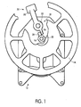
- FIG. 1 of the drawings Illustrated therein is an apparatus, generally designated 10, for operating a railway car hand brake, generally designated 12.
- the apparatus 10 comprises a hand brake wheel 14, having a hub 16 fixed on an operating shaft 20.
- the operating shaft 20 is rotatably mounted on the hand brake 12.
- the hub 16 of the hand brake wheel 14 further has a reaction member 24.
- the reaction member 24 is a lug of a predetermined size and shape, disposed on the perimeter of the hub 16 of the hand brake wheel 14.
- a brake release mechanism, generally designated 30, is fixed on a brake release shaft 22.
- the brake release shaft 22 is rotatably mounted on the hand brake 12.
- the reaction member 24 is engageable with the brake release mechanism 30 when the hand brake wheel 14 is rotated.
- the brake release mechanism 30 includes an activation means 26, fixed on the brake release mechanism 30 for engagement with the reaction member 24 when the hand brake wheel 14 is rotated.
- the rotation direction of the hand brake wheel 14 to apply the hand brake 12 is clockwise.
- the activation means 26 is a trigger lever of a predetermined size and shape.
- the brake release mechanism 30 further include a quick release lever 32. The position of the brake release mechanism 30 will provide a visual indicator of the brake status.
- FIG. 10 Illustrated therein is an apparatus, generally designated 10, for remotely operating a railcar vertical wheel hand brake (not shown) a predetermined distance from the hand brake.
- the apparatus 10 comprises a hand brake wheel 14, located a predetermined distance from the hand brake.
- the hand brake wheel 14 has a hub 16, fixed on a first shaft 18.
- the first shaft 18 is engageable with an operating shaft (not shown) rotatably mounted on the hand brake.
- the hub 16 of the hand brake wheel 14 further includes a reaction member 24.
- the reaction member 24 is a lug disposed on the perimeter of the hub 16 of the hand brake wheel 14.
- An activation means 26 is fixed on a second shaft 28, and the second shaft 28 is rotatably mounted a predetermined distance from the first shaft 18.
- the activation means 26 is engageable with the reaction member 24 when the hand brake wheel 14 is rotated, which rotates the second shaft 28 in an opposing direction to the rotation of the hand brake wheel 14.
- the activation means 26 is a trigger lever of a predetermined size and shape.
- the second shaft 28 is engageable with a brake release shaft (not shown) rotatably mounted on the hand brake.
- a brake release mechanism, generally designated 30, is fixed on a third shaft 34.
- the brake release mechanism 30 further includes a quick release lever 32.
- the third shaft 34 is rotatably mounted a predetermined distance from the first shaft 18.
- the third shaft 34 is articulately connected to the second shaft 28 to rotate the third shaft 34 substantially in conjunction with the second shaft 28 when the hand brake wheel 14 is rotated.
- levers 36, links 38, pins 40, and a rod 42 articulately connect the second shaft 28 and the third shaft 34. It is also preferred to rotate the hand brake wheel 14 in a clockwise direction to apply the hand brake.
- the hand brake can be remotely operated from a predetermined location on a railcar when the first shaft 18 is connected to the operating shaft of the hand brake.
- an apparatus for remotely operating a railcar vertical wheel hand brake, generally designated 46, a predetermined distance from the hand brake 46.
- the apparatus 44 comprises a first hand brake wheel 48 located a predetermined distance from the hand brake.
- the first hand brake wheel 48 has a hub 50 fixed on a first shaft 52.
- the first shaft 52 is engageable with a first operating shaft 54 rotatably mounted on a first side 58 of the hand brake 46.
- the first hand brake wheel 48 has a reaction member 60.
- the reaction member 60 is a lug disposed on the perimeter of the hub 50 of the first hand brake wheel 48.
- An activation means 62 is fixed on a second shaft 64, which is rotatably mounted a predetermined distance from the first shaft 52.
- the activation means 62 is engageable with the reaction member 60 when the first hand brake wheel 48 is rotated.
- the activation means 62 is a trigger lever of a predetermined size and shape.
- the second shaft 64 is rotated in an opposing direction to the rotation of the first hand brake wheel 48.
- the second shaft 64 is engageable with a brake release shaft 56 rotatably mounted on the hand brake 46.
- a first brake release mechanism is fixed on a third shaft 68.
- the first brake release mechanism 66 further includes a quick release lever 70.
- the third shaft 68 is rotatably mounted a predetermined distance from the first shaft 52.
- the third shaft 68 is articulately connected to the second shaft 64.
- levers 72, links 74, pins 76, and a rod 78 articulately connect the second shaft 64 to the third shaft 68.
- a second hand brake wheel 80 is substantially opposed to the first hand brake wheel 48, and is located a predetermined distance from the hand brake 46.
- the second hand brake wheel 80 has a hub 82 fixed on a fourth shaft 84.
- the fourth shaft 84 is engageable with a second operating shaft 86 rotatably mounted on a second side 59 of the hand brake 46.
- a second brake release mechanism is fixed on a fifth shaft 90, which is rotatably mounted a predetermined from the fourth shaft 84.
- the second brake release mechanism 88 further includes a quick release lever 92.
- a sixth shaft 94 is rotatably mounted and substantially opposed to the third shaft 68 of the first brake release mechanism 66. The sixth shaft 94 is engageable with the third shaft 68.
- the fifth shaft 90 is articulately connected to the sixth shaft 94.
- levers 96, links 98, pins 100, and a rod 102 articulately connect the fifth shaft 90 to the sixth shaft 94.
- the second shaft 64, third shaft 68, fifth shaft 90, and sixth shaft 94 will rotate substantially in conjunction when at least one of the first hand brake wheel 48 and the second hand brake wheel 80 is rotated.
- the rotation direction of the first hand brake wheel 48 and the second hand brake wheel 80 is clockwise.
- the railcar hand brake 46 can be remotely operated from the opposing sides of the railcar when the first shaft 52 is connected to the first operating shaft 54, and the fourth shaft 84 is connected to the second operating shaft 86 of the hand brake 46.
- FIG. 1 Illustrated therein is an improvement in combination with a railcar vertical hand brake, generally designated 12, having at least one operating shaft 20, and a brake release shaft 22.
- the hand brake 12 is mounted in a predetermined position on a railcar, generally designated 104.
- the hand brake 12 is mounted on the center sill 106 of the railcar.
- the improvement comprises a hand brake wheel 14, located a predetermined distance from the hand brake 12.
- the hand brake wheel 14 has a hub 16, fixed on a first shaft 18.
- the hand wheel 14 is mounted on a side of the railcar 104.
- the first shaft 18 is connected to the operating shaft 20 rotatably mounted on the hand brake 12.
- an elongated member 108 of a predetermined length and shape connects the first shaft 18 to the operating shaft 20.
- the hand brake wheel 14 further includes a reaction member 24.
- the reaction member 24 is a lug disposed on the perimeter of the hub 16 of the hand brake wheel 14.
- An activation means 26 is fixed on a second shaft 28, and the second shaft 28 is rotatably mounted a predetermined distance from the first shaft 18.
- the activation means 26 is engageable with the reaction member 24 when the hand brake wheel 14 is rotated, which rotates the second shaft 28 in an opposing direction to the rotation of the hand brake wheel 14.
- the activation means 26 is a trigger lever of a predetermined size and shape.
- the second shaft 28 is connected to the brake release shaft 22 rotatably mounted on the hand brake 12.
- a second elongated member 110 of a predetermined length and shape connects the second shaft 28 to the brake release shaft 22.
- a brake release mechanism, generally designated 30, is fixed on a third shaft 34.
- the brake release mechanism 30 further includes a quick release lever 32.
- the third shaft 34 is rotatably mounted a predetermined distance from the first shaft 18.
- the third shaft 34 is articulately connected to the second shaft 28 to rotate the third shaft 34 substantially in conjunction with the second shaft 28 when the hand brake wheel 14 is rotated.
- levers 36, links 38, pins, 40, and a rod 42 articulately connect the second shaft 28 and the third shaft 34. It is also preferred to rotate the hand brake wheel 14 in a clockwise direction to apply the hand brake 12.
- the hand brake 12 can be remotely operated from a predetermined location on the railcar.
- FIG. 46 Illustrated therein is an improvement in combination with a railcar vertical hand brake, generally designated 46, having a first operating shaft 54 rotatably mounted on the first side 58 of the hand brake 46, a second operating shaft 86 rotatably mounted on the second side 59 of the hand brake 46, and a brake release shaft 56 rotatably mounted on the first side 58 of the hand brake 46.
- the hand brake 46 is mounted in a predetermined position on a railcar, generally designated 104.
- the hand brake 46 is mounted adjacent a center sill 106 of the railcar 104.
- a first hand brake wheel 48 is located a predetermined distance from the hand brake 46.
- the first hand brake wheel 48 is mounted on a side of the railcar 104.
- the first hand brake wheel 48 has a hub 50 fixed on a first shaft 52.
- the first shaft 52 is connected to the first operating shaft 54.
- an elongated member 112 of a predetermined length and shape connects the first shaft 52 to the first operating shaft 54.
- the first hand brake wheel 48 has a reaction member 60.
- the reaction member 60 is a lug disposed on the perimeter of the hub 50 of the first hand brake wheel 48.
- An activation means 62 is fixed on a second shaft 64, which is rotatably mounted a predetermined distance from the first shaft 52.
- the activation means 62 is engageable with the reaction member 60 when the first hand brake wheel 48 is rotated.
- the activation means 62 is a trigger lever of a predetermined size and shape.
- the second shaft 64 is rotated in an opposing direction to the rotation of the first hand brake wheel 48.
- the second shaft 64 is connected to the brake release shaft 56.
- a second elongated member 114 of a predetermined length and shape connects the second shaft 64 to the brake release shaft 56.
- a first brake release mechanism is fixed on a third shaft 68.
- the first brake release mechanism 66 further includes a quick release lever 70.
- the third shaft 68 is rotatably mounted a predetermined distance from the first shaft 52.
- the third shaft 68 is articulately connected to the second shaft 64.
- levers 72, links 74, pins 76, and a rod 78 articulately connect the second shaft 64 to the third shaft 68.
- a second hand brake wheel 80 is substantially opposed to the first hand brake wheel 48, and is located a predetermined distance from the hand brake 46.
- the second hand brake wheel 80 is mounted on a side of the railcar 104.
- the second hand brake wheel 80 has a hub 82 fixed on a fourth shaft 84.
- the fourth shaft 84 is connected to the second operating shaft 86.
- a third elongated member 116 of a predetermined length and shape connects the fourth shaft 84 to the second operating shaft 86.
- a second brake release mechanism is fixed on a fifth shaft 90, which is rotatably mounted a predetermined distance from the fourth shaft 84.
- the second brake release mechanism 88 further includes a quick release lever 92.
- a sixth shaft 94 is rotatably mounted and substantially opposed to the third shaft 68 of the first brake release mechanism 66.
- an elongated element 118 of a predetermined length and shape connects the sixth shaft 94 to the third shaft 68.
- the fifth shaft 90 is articulately connected to the sixth shaft 94.
- levers 96, links 98, pins 100, and a rod 102 articulately connect the fifth shaft 90 to the sixth shaft 94.
- the second shaft 64, third shaft 68, fifth shaft 90, and sixth shaft 94 will rotate substantially in conjunction when at least one of the first hand brake wheel 48 and the second hand brake wheel 80 is rotated.
- the rotation direction of the first hand brake wheel 48 and the second hand brake wheel 80 is clockwise, therefore a gear box 120 is provided to compensate when the hand brake 46 is operated from the second side 59.
- the railcar hand brake 46 can be remotely operated, and the brake status can be determined, from the opposing sides of the railcar.
- the release lever 32 of the quick release mechanism 30 is rotated clockwise into the release position. This rotates the second shaft 28 clockwise, which synchronously rotates the attached brake release shaft 22, releasing the winding gear of the hand brake 12.
- the release lever 32 remains in this position as a positive visual indicator that the brakes are released.
- first hand brake wheel 48 When brake application is desired on a railcar with a remote hand brake operation on both sides of the car, the operator turns either the first hand brake wheel 48, or the second hand brake wheel 80 in a clockwise direction.
- the first hand brake wheel 48 is located on the side of the railcar facing the first side 58 of the hand brake 46 located adjacent the center sill, and the second hand brake wheel 80 is located on the opposite side, or facing the second side 59 of the hand brake 46 having the gear box 120.
- first hand brake wheel 48 If the first hand brake wheel 48 is rotated clockwise, the first shaft 52 connected to the first operating shaft 54 of the hand brake 46 causes the first operating shaft 54 to rotate, whereby brake application begins.
- the reaction member 60 simultaneously rotates into the activation means 62, rotating the second shaft 64 counterclockwise, which rotates the third shaft 68 counterclockwise because it is articulately connected to the second shaft 64.
- the brake release shaft 56 also rotates counterclockwise when the second shaft 64 is rotated.
- the release lever 70 of the first brake release mechanism 66 rotates counterclockwise and drops into the applied position, indicating brake application.
- the sixth shaft 94 connected to the third shaft 68, rotates counterclockwise.
- the fifth shaft 90 articulately connected to the sixth shaft 94, rotates clockwise, and causes the release lever 92 of the second brake release mechanism 88 to rotate clockwise and drop into the applied position, indicating brake application.
- the brake is remotely applied from the first side 58 of the hand brake 46, but brake application can be determined from either side of the car by visual observation of the release levers 70 and 92.
- the fourth shaft 84 connected to the second operating shaft 86 of the hand brake 46 causes the second operating shaft 86 to rotate, whereby brake application begins.
- the gear box 120 to which the second operating shaft 86 is connected, corrects the rotational direction to allow the second hand brake wheel 80 to be rotated in the same clockwise direction.
- the reaction member 60 rotates into and engages with the activation means 62.
- the activation means 62 rotates the second shaft 64 in a counterclockwise direction, causing the third shaft 68, which is articulately connected to the second shaft 64, to simultaneously rotate in the counterclockwise direction.
- the release lever 70 of the first brake release mechanism 66 rotates and drops into the applied position.
- the sixth shaft 94 located on the opposing side of the railcar and connected to the third shaft 68, rotates simultaneously, causing the articulately connected fifth shaft 90 to rotate clockwise and drop into the applied position.
- the brake is remotely applied from the second side 59 of the hand brake 46, but brake application can be determined from either side of the car by visual observation of the release levers 70 and 92.
- Brake release is achieved in a similar manner by rotating one of the release levers 70 and 92 in a clockwise direction to disengage the winding gear of the hand brake 46.
- the brake is remotely released from either side of the railcar 104, and can also be determined from either side of the car by visual observation of the release levers 70 and 92.
Landscapes
- Engineering & Computer Science (AREA)
- Mechanical Engineering (AREA)
- Transportation (AREA)
- Braking Arrangements (AREA)
- Braking Elements And Transmission Devices (AREA)
- Valves And Accessory Devices For Braking Systems (AREA)
Abstract
Description
- The present invention relates, in general, to a vertical wheel hand brake, and more particularly, to an apparatus for operating a vertical wheel hand brake.
- Prior to the present invention, a railcar vertical hand brake includes a brake release mechanism that provides quick release of the brakes to permit free rotation of the winding gear. When a force is exerted on the release lever to move the attached brake release shaft, the main gear wheel is released, releasing the tension on the brake chain, which in turn releases the brake. Removing the force on the release lever re-engages the main gear wheel. However, the brake may not be fully released before the force is removed from the release lever. This condition will usually not be apparent to the operator. As the railcar negotiates a curve in the track, the truck rotates and can exert a pulling force on the brake chain. This action can apply the brakes to the truck while the train is in motion, resulting in friction and premature wear between the brake shoes and the wheels, and the wheels and the rail.
- Furthermore, a railcar vertical wheel hand brake is located on an end of the railcar. When the railcars are coupled together, the operator has to walk between two cars to apply and release the brakes. This practice not only poses a potential danger to the operator, but also is inefficient.
- An example of this type hand brake is taught in U.S. Patent No. 4,368,648. The teachings of this reference are incorporated herein by reference thereto.
- In a first aspect, the present invention provides an apparatus for operating a railway car vertical hand brake. The apparatus comprises a hand brake wheel having a hub fixed on an operating shaft rotatably mounted on the hand brake. The hand brake wheel further has a reaction member. A brake release mechanism is fixed on a brake release shaft which is rotatably mounted on the hand brake. The reaction member is engageable with the brake release mechanism when the hand brake is rotated. The position of the brake release mechanism will provide a visual indicator of the brake status.
- In a further aspect, the present invention provides an apparatus for remotely operating a railcar vertical hand brake a predetermined distance from the railcar hand brake. The apparatus comprises a hand brake wheel located a predetermined distance from the hand brake. The hand brake wheel has a hub fixed on a first shaft, and the first shaft is engageable with an operating shaft rotatably mounted on the hand brake of the railcar. The hand brake wheel also has a reaction member. An activation means is fixed on a second shaft. The second shaft is rotatably mounted a predetermined distance from the first shaft. The activation means is engageable with the reaction member when the hand brake wheel is rotated, rotating the second shaft in an opposing direction to the rotation of the hand brake wheel. The second shaft is engageable with a brake release shaft rotatably mounted on the hand brake. A brake release mechanism is fixed on a third shaft, which is rotatably mounted a predetermined distance from the first shaft. The third shaft is articulately connected to the second shaft to rotate the third shaft in conjunction with the second shaft when the hand brake wheel is rotated. The hand brake can be remotely operated, and the brake status can be determined from a predetermined location on a railway car when the first shaft is connected to the operating shaft of the hand brake.
- In still a further aspect, the present invention provides an apparatus for remotely operating a railcar vertical hand brake a predetermined distance from the railcar hand brake. The apparatus comprises a first hand brake wheel located a predetermined distance from the hand brake. The first hand brake wheel has a hub fixed on a first shaft. The first shaft is engageable with a first operating shaft mounted on a first side of the hand brake. The first hand brake wheel also has a reaction member. An activation means is fixed on a second shaft, and the second shaft is rotatably mounted a predetermined distance from the first shaft. The activation means is engageable with the reaction member when the first hand brake wheel is rotated, rotating the second shaft in an opposing direction to the rotation of the first hand brake wheel. The second shaft is engageable with a brake release shaft rotatably mounted on the hand brake. A first brake release mechanism is fixed on a third shaft, which is rotatably mounted a predetermined distance from the first shaft. The third shaft is articulately connected to the second shaft. A second hand brake wheel is substantially opposed to the first hand brake wheel, and is located a predetermined distance from the hand brake. The second hand brake wheel has a hub fixed on a fourth shaft, which is engageable with a second operating shaft rotatably mounted on a second side of the hand brake. A second brake release mechanism is fixed on a fifth shaft which is rotatably mounted a predetermined distance from the fourth shaft. A sixth shaft is rotatably mounted and substantially opposed to the third shaft of the first brake release mechanism. An elongated member of a predetermined length and shape connects the sixth shaft to the third shaft. The fifth shaft is articulately connected to the sixth shaft, whereby the second, third, fifth, and sixth shafts will rotate in conjunction when at least one of the first hand brake wheel and the second hand brake wheel is rotated. The railcar hand brake can be remotely operated from opposing sides of the railcar, and the brake status can be determined, when the first shaft is connected to the first operating shaft, and the fourth shaft is connected to the second operating shaft of the hand brake.
- In still a further aspect, the present invention provides an improvement in combination with a railcar vertical hand brake having at least one operating shaft and release mechanism, which is mounted in a predetermined position on a the railcar. The improvement comprises a hand brake wheel having a hub fixed on a first shaft. The hand brake wheel is mounted a predetermined distance from the hand brake, and the first shaft is connected to the operating shaft which is rotatably mounted a predetermined distance from the first shaft. The brake wheel also has a reaction member. An activation means is fixed on a second shaft, and the second shaft is rotatably mounted a predetermined distance from the first shaft. The activation means is engageable with the reaction member when the hand brake wheel is rotated, which rotates the second shaft in an opposing direction to the rotation of the hand brake. The second shaft is connected to a brake release shaft rotatably mounted on the hand brake. A brake release mechanism is fixed on a third shaft, which is rotatably mounted a predetermined distance from the first shaft. The third shaft is articulately connected to the second shaft to rotate the third shaft in conjunction with the second shaft when the hand brake wheel is rotated. The hand brake wheel can be remotely operated, and the brake status determined, from a predetermined location on the railcar.
- In still a further aspect, the present invention provides an improvement in combination with a railcar vertical hand brake having a first operating shaft rotatably mounted on a first side of the hand brake, a second operating shaft rotatably mounted on a second side of the hand brake, and a brake release mechanism, which is mounted in a predetermined position on a the railcar. The improvement comprises a first hand brake wheel located a predetermined distance from the hand brake. The first hand brake wheel has a hub fixed on a first shaft. The first shaft is connected to the first operating shaft mounted on a first side of the hand brake. The first hand brake wheel also has a reaction member. An activation means is fixed on a second shaft, and the second shaft is rotatably mounted a predetermined distance from the first shaft. The activation means is engageable with the reaction member when the first hand brake wheel is rotated, rotating the second shaft in an opposing direction to the rotation of the first hand brake wheel. The second shaft is connected to a brake release shaft rotatably mounted on the hand brake. A first brake release mechanism is fixed on a third shaft, which is rotatably mounted a predetermined distance from the first shaft. The third shaft is articulately connected to the second shaft. A second hand brake wheel is substantially opposed to the first hand brake wheel, and is located a predetermined distance from the hand brake. The second hand brake wheel has a hub fixed on a fourth shaft, which is engageable with the second operating shaft. A second brake release mechanism is fixed on a fifth shaft which is rotatably mounted a predetermined distance from the fourth shaft. A sixth shaft is rotatably mounted and substantially opposed to the third shaft of the first brake release mechanism. An elongated member of a predetermined length and shape connects the sixth shaft to the third shaft. The fifth shaft is articulately connected to the sixth shaft. The second, third, fifth, and sixth shafts will rotate substantially in conjunction when at least one of the first hand brake wheel and the second hand brake wheel is rotated. The railcar hand brake can be remotely operated, and the brake status determined, from opposing sides of the railcar.
- It is therefore a primary object of the present invention to provide an apparatus for operating a railcar vertical wheel hand brake.
- Another object of the present invention is to provide an apparatus for operating a railcar vertical wheel hand brake that will provide a definitive visual indicator to the operator that the brakes are in the applied or released mode.
- Another object of the present invention is to provide an apparatus for remotely operating a railcar vertical wheel hand brake a predetermined distance from the railcar to increase operator safety.
- Another object of the present invention is to provide an apparatus for remotely operating a railcar vertical wheel hand brake a predetermined distance from the railcar to increase operator efficiency.
- Another object of the present invention is to provide an apparatus for remotely operating a railcar vertical wheel hand brake a predetermined distance from the railcar to reduce inadvertent brake applications by maintaining the brake release mechanism in the release position until brake application is desired.
- Still another object of the present invention is to provide an apparatus for remotely operating a railcar vertical wheel hand brake a predetermined distance from the railcar that will provide a definitive visual indicator to the operator that the brakes are in the applied or released mode.
- In addition to the various objects of the invention that have been described above, various other objects and advantages of the invention will become more readily apparent to those persons skilled in the relevant art from the following more detailed description of the invention, particularly, when such description is taken in conjunction with the attached drawing figures and the appended claims.
-
- Figure 1 is an elevation view of the present invention with a section removed to reveal the features of the present invention;
- Figure 2 is an elevation view of an alternative embodiment of the present invention;
- Figure 3 is a top view of an alternative embodiment of the present invention;
- Figure 4 is a top sectional view of an alternative embodiment of the present invention;
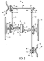
- Figure 5 is a top view of an alternative embodiment of the present invention; and
- Figure 6 is a top sectional view of another alternative embodiment of the present invention.
-
- Prior to proceeding to a more detailed description of the invention, it should be noted that identical components having identical functions have been designated with identical reference numerals for the sake of clarity.
- Now refer more particularly to Figure 1 of the drawings. Illustrated therein is an apparatus, generally designated 10, for operating a railway car hand brake, generally designated 12. The
apparatus 10 comprises ahand brake wheel 14, having ahub 16 fixed on an operatingshaft 20. The operatingshaft 20 is rotatably mounted on thehand brake 12. Thehub 16 of thehand brake wheel 14 further has areaction member 24. Preferably, thereaction member 24 is a lug of a predetermined size and shape, disposed on the perimeter of thehub 16 of thehand brake wheel 14. A brake release mechanism, generally designated 30, is fixed on abrake release shaft 22. Thebrake release shaft 22 is rotatably mounted on thehand brake 12. Thereaction member 24 is engageable with thebrake release mechanism 30 when thehand brake wheel 14 is rotated. Preferably, thebrake release mechanism 30 includes an activation means 26, fixed on thebrake release mechanism 30 for engagement with thereaction member 24 when thehand brake wheel 14 is rotated. Preferably, the rotation direction of thehand brake wheel 14 to apply thehand brake 12 is clockwise. Preferably, the activation means 26 is a trigger lever of a predetermined size and shape. Also preferred is that thebrake release mechanism 30 further include aquick release lever 32. The position of thebrake release mechanism 30 will provide a visual indicator of the brake status. - Now refer more particularly to Figures 2 and 3 of the drawings. Illustrated therein is an apparatus, generally designated 10, for remotely operating a railcar vertical wheel hand brake (not shown) a predetermined distance from the hand brake. The
apparatus 10 comprises ahand brake wheel 14, located a predetermined distance from the hand brake. Thehand brake wheel 14 has ahub 16, fixed on afirst shaft 18. Thefirst shaft 18 is engageable with an operating shaft (not shown) rotatably mounted on the hand brake. Thehub 16 of thehand brake wheel 14 further includes areaction member 24. Preferably, thereaction member 24 is a lug disposed on the perimeter of thehub 16 of thehand brake wheel 14. - An activation means 26 is fixed on a
second shaft 28, and thesecond shaft 28 is rotatably mounted a predetermined distance from thefirst shaft 18. The activation means 26 is engageable with thereaction member 24 when thehand brake wheel 14 is rotated, which rotates thesecond shaft 28 in an opposing direction to the rotation of thehand brake wheel 14. Preferably, the activation means 26 is a trigger lever of a predetermined size and shape. Thesecond shaft 28 is engageable with a brake release shaft (not shown) rotatably mounted on the hand brake. - A brake release mechanism, generally designated 30, is fixed on a
third shaft 34. Preferably, thebrake release mechanism 30 further includes aquick release lever 32. Thethird shaft 34 is rotatably mounted a predetermined distance from thefirst shaft 18. Thethird shaft 34 is articulately connected to thesecond shaft 28 to rotate thethird shaft 34 substantially in conjunction with thesecond shaft 28 when thehand brake wheel 14 is rotated. Preferably, levers 36,links 38, pins 40, and arod 42 articulately connect thesecond shaft 28 and thethird shaft 34. It is also preferred to rotate thehand brake wheel 14 in a clockwise direction to apply the hand brake. The hand brake can be remotely operated from a predetermined location on a railcar when thefirst shaft 18 is connected to the operating shaft of the hand brake. - Now refer more particularly to Figure 5 of the drawings. Illustrated therein is an apparatus, generally designated 44, for remotely operating a railcar vertical wheel hand brake, generally designated 46, a predetermined distance from the
hand brake 46. Theapparatus 44 comprises a firsthand brake wheel 48 located a predetermined distance from the hand brake. The firsthand brake wheel 48 has ahub 50 fixed on afirst shaft 52. Thefirst shaft 52 is engageable with afirst operating shaft 54 rotatably mounted on afirst side 58 of thehand brake 46. The firsthand brake wheel 48 has areaction member 60. Preferably, thereaction member 60 is a lug disposed on the perimeter of thehub 50 of the firsthand brake wheel 48. - An activation means 62 is fixed on a
second shaft 64, which is rotatably mounted a predetermined distance from thefirst shaft 52. The activation means 62 is engageable with thereaction member 60 when the firsthand brake wheel 48 is rotated. Preferably, the activation means 62 is a trigger lever of a predetermined size and shape. Thesecond shaft 64 is rotated in an opposing direction to the rotation of the firsthand brake wheel 48. Thesecond shaft 64 is engageable with abrake release shaft 56 rotatably mounted on thehand brake 46. - A first brake release mechanism, generally designated 66, is fixed on a
third shaft 68. Preferably, the firstbrake release mechanism 66 further includes aquick release lever 70. Thethird shaft 68 is rotatably mounted a predetermined distance from thefirst shaft 52. Thethird shaft 68 is articulately connected to thesecond shaft 64. Preferably, levers 72,links 74, pins 76, and arod 78 articulately connect thesecond shaft 64 to thethird shaft 68. - A second
hand brake wheel 80 is substantially opposed to the firsthand brake wheel 48, and is located a predetermined distance from thehand brake 46. The secondhand brake wheel 80 has ahub 82 fixed on afourth shaft 84. Thefourth shaft 84 is engageable with asecond operating shaft 86 rotatably mounted on asecond side 59 of thehand brake 46. - A second brake release mechanism, generally designated 88, is fixed on a
fifth shaft 90, which is rotatably mounted a predetermined from thefourth shaft 84. Preferably, the secondbrake release mechanism 88 further includes aquick release lever 92. Asixth shaft 94 is rotatably mounted and substantially opposed to thethird shaft 68 of the firstbrake release mechanism 66. Thesixth shaft 94 is engageable with thethird shaft 68. - The
fifth shaft 90 is articulately connected to thesixth shaft 94. Preferably, levers 96,links 98, pins 100, and arod 102 articulately connect thefifth shaft 90 to thesixth shaft 94. Thesecond shaft 64,third shaft 68,fifth shaft 90, andsixth shaft 94 will rotate substantially in conjunction when at least one of the firsthand brake wheel 48 and the secondhand brake wheel 80 is rotated. Preferably, the rotation direction of the firsthand brake wheel 48 and the secondhand brake wheel 80 is clockwise. Therailcar hand brake 46 can be remotely operated from the opposing sides of the railcar when thefirst shaft 52 is connected to thefirst operating shaft 54, and thefourth shaft 84 is connected to thesecond operating shaft 86 of thehand brake 46. - Now refer more particularly to Figures 2, 3 and 4 of the drawings. Illustrated therein is an improvement in combination with a railcar vertical hand brake, generally designated 12, having at least one operating
shaft 20, and abrake release shaft 22. Thehand brake 12 is mounted in a predetermined position on a railcar, generally designated 104. Preferably, thehand brake 12 is mounted on thecenter sill 106 of the railcar. The improvement comprises ahand brake wheel 14, located a predetermined distance from thehand brake 12. Thehand brake wheel 14 has ahub 16, fixed on afirst shaft 18. Preferably, thehand wheel 14 is mounted on a side of therailcar 104. Thefirst shaft 18 is connected to the operatingshaft 20 rotatably mounted on thehand brake 12. Preferably, anelongated member 108 of a predetermined length and shape connects thefirst shaft 18 to the operatingshaft 20. Thehand brake wheel 14 further includes areaction member 24. Preferably, thereaction member 24 is a lug disposed on the perimeter of thehub 16 of thehand brake wheel 14. An activation means 26 is fixed on asecond shaft 28, and thesecond shaft 28 is rotatably mounted a predetermined distance from thefirst shaft 18. The activation means 26 is engageable with thereaction member 24 when thehand brake wheel 14 is rotated, which rotates thesecond shaft 28 in an opposing direction to the rotation of thehand brake wheel 14. Preferably, the activation means 26 is a trigger lever of a predetermined size and shape. Thesecond shaft 28 is connected to thebrake release shaft 22 rotatably mounted on thehand brake 12. Preferably, a secondelongated member 110 of a predetermined length and shape connects thesecond shaft 28 to thebrake release shaft 22. - A brake release mechanism, generally designated 30, is fixed on a
third shaft 34. Preferably, thebrake release mechanism 30 further includes aquick release lever 32. Thethird shaft 34 is rotatably mounted a predetermined distance from thefirst shaft 18. Thethird shaft 34 is articulately connected to thesecond shaft 28 to rotate thethird shaft 34 substantially in conjunction with thesecond shaft 28 when thehand brake wheel 14 is rotated. Preferably, levers 36,links 38, pins, 40, and arod 42 articulately connect thesecond shaft 28 and thethird shaft 34. It is also preferred to rotate thehand brake wheel 14 in a clockwise direction to apply thehand brake 12. Thehand brake 12 can be remotely operated from a predetermined location on the railcar. - Now refer more particularly to Figures 5 and 6 of the drawings. Illustrated therein is an improvement in combination with a railcar vertical hand brake, generally designated 46, having a
first operating shaft 54 rotatably mounted on thefirst side 58 of thehand brake 46, asecond operating shaft 86 rotatably mounted on thesecond side 59 of thehand brake 46, and abrake release shaft 56 rotatably mounted on thefirst side 58 of thehand brake 46. Thehand brake 46 is mounted in a predetermined position on a railcar, generally designated 104. Preferably, thehand brake 46 is mounted adjacent acenter sill 106 of therailcar 104. A firsthand brake wheel 48 is located a predetermined distance from thehand brake 46. Preferably, the firsthand brake wheel 48 is mounted on a side of therailcar 104. The firsthand brake wheel 48 has ahub 50 fixed on afirst shaft 52. Thefirst shaft 52 is connected to thefirst operating shaft 54. Preferably, anelongated member 112 of a predetermined length and shape connects thefirst shaft 52 to thefirst operating shaft 54. The firsthand brake wheel 48 has areaction member 60. Preferably, thereaction member 60 is a lug disposed on the perimeter of thehub 50 of the firsthand brake wheel 48. - An activation means 62 is fixed on a
second shaft 64, which is rotatably mounted a predetermined distance from thefirst shaft 52. The activation means 62 is engageable with thereaction member 60 when the firsthand brake wheel 48 is rotated. Preferably, the activation means 62 is a trigger lever of a predetermined size and shape. Thesecond shaft 64 is rotated in an opposing direction to the rotation of the firsthand brake wheel 48. Thesecond shaft 64 is connected to thebrake release shaft 56. Preferably, a secondelongated member 114 of a predetermined length and shape connects thesecond shaft 64 to thebrake release shaft 56. - A first brake release mechanism, generally designated 66, is fixed on a
third shaft 68. Preferably, the firstbrake release mechanism 66 further includes aquick release lever 70. Thethird shaft 68 is rotatably mounted a predetermined distance from thefirst shaft 52. Thethird shaft 68 is articulately connected to thesecond shaft 64. Preferably, levers 72,links 74, pins 76, and arod 78 articulately connect thesecond shaft 64 to thethird shaft 68. - A second
hand brake wheel 80 is substantially opposed to the firsthand brake wheel 48, and is located a predetermined distance from thehand brake 46. Preferably, the secondhand brake wheel 80 is mounted on a side of therailcar 104. The secondhand brake wheel 80 has ahub 82 fixed on afourth shaft 84. Thefourth shaft 84 is connected to thesecond operating shaft 86. Preferably, a thirdelongated member 116 of a predetermined length and shape connects thefourth shaft 84 to thesecond operating shaft 86. - A second brake release mechanism, generally designated 88, is fixed on a
fifth shaft 90, which is rotatably mounted a predetermined distance from thefourth shaft 84. Preferably, the secondbrake release mechanism 88 further includes aquick release lever 92. - A
sixth shaft 94 is rotatably mounted and substantially opposed to thethird shaft 68 of the firstbrake release mechanism 66. Preferably, anelongated element 118 of a predetermined length and shape connects thesixth shaft 94 to thethird shaft 68. - The
fifth shaft 90 is articulately connected to thesixth shaft 94. Preferably, levers 96,links 98, pins 100, and arod 102 articulately connect thefifth shaft 90 to thesixth shaft 94. Thesecond shaft 64,third shaft 68,fifth shaft 90, andsixth shaft 94 will rotate substantially in conjunction when at least one of the firsthand brake wheel 48 and the secondhand brake wheel 80 is rotated. Preferably, the rotation direction of the firsthand brake wheel 48 and the secondhand brake wheel 80 is clockwise, therefore agear box 120 is provided to compensate when thehand brake 46 is operated from thesecond side 59. Therailcar hand brake 46 can be remotely operated, and the brake status can be determined, from the opposing sides of the railcar. - Now refer again to Figure 1 of the drawings. When brake application is desired, the operator turns the
hand brake wheel 14 in a clockwise direction. Thereaction member 24 turns simultaneously and engages with the activation means 26 of thebrake release mechanism 30. This engagement causes thebrake release shaft 22 and therelease lever 32 of thebrake release mechanism 30 to rotate in a counter-clockwise direction, whereby, with the assistance of gravity, therelease lever 32 drops into the brake applied position. The winding gear (not shown) of thehand brake 12 is now re-engaged to permit brake application. When brake release is required, therelease lever 32 of thequick release mechanism 30 is rotated clockwise into the release position. The position of therelease lever 32 visually indicates that thehand brake 12 has been applied or released. - Now refer again to Figures 2, 3, and 4 of the drawings. When brake application is desired on a single remote hand brake operation, the operator turns the
hand brake wheel 14 in a clockwise direction. When thefirst shaft 18 is connected to the operatingshaft 20 of thehand brake 12, this action causes the operatingshaft 20 to rotate, whereby brake application begins, while thereaction member 24 simultaneously rotates into and engages with the activation means 26. The activation means 26 and thesecond shaft 28 then rotate in the counterclockwise direction, which engages the winding gear (not shown) of thehand brake 12. Thesecond shaft 28 is articulately connected to thethird shaft 34, therefore thethird shaft 34 rotates in conjunction. This counterclockwise rotation of thethird shaft 34 causes therelease lever 32 of thebrake release mechanism 30 to rotate in the same counterclockwise direction. Therelease lever 32 drops into the applied position to indicate that the brakes are applied. - When brake release is required, the
release lever 32 of thequick release mechanism 30 is rotated clockwise into the release position. This rotates thesecond shaft 28 clockwise, which synchronously rotates the attachedbrake release shaft 22, releasing the winding gear of thehand brake 12. Therelease lever 32 remains in this position as a positive visual indicator that the brakes are released. - Now refer again to Figures 5 and 6 of the drawings. When brake application is desired on a railcar with a remote hand brake operation on both sides of the car, the operator turns either the first
hand brake wheel 48, or the secondhand brake wheel 80 in a clockwise direction. The firsthand brake wheel 48 is located on the side of the railcar facing thefirst side 58 of thehand brake 46 located adjacent the center sill, and the secondhand brake wheel 80 is located on the opposite side, or facing thesecond side 59 of thehand brake 46 having thegear box 120. - If the first
hand brake wheel 48 is rotated clockwise, thefirst shaft 52 connected to thefirst operating shaft 54 of thehand brake 46 causes thefirst operating shaft 54 to rotate, whereby brake application begins. Thereaction member 60 simultaneously rotates into the activation means 62, rotating thesecond shaft 64 counterclockwise, which rotates thethird shaft 68 counterclockwise because it is articulately connected to thesecond shaft 64. Thebrake release shaft 56 also rotates counterclockwise when thesecond shaft 64 is rotated. Therelease lever 70 of the firstbrake release mechanism 66 rotates counterclockwise and drops into the applied position, indicating brake application. Thesixth shaft 94, connected to thethird shaft 68, rotates counterclockwise. Thefifth shaft 90, articulately connected to thesixth shaft 94, rotates clockwise, and causes therelease lever 92 of the secondbrake release mechanism 88 to rotate clockwise and drop into the applied position, indicating brake application. Thus, the brake is remotely applied from thefirst side 58 of thehand brake 46, but brake application can be determined from either side of the car by visual observation of the release levers 70 and 92. - If the second
hand brake wheel 80 is rotated clockwise, thefourth shaft 84 connected to thesecond operating shaft 86 of thehand brake 46 causes thesecond operating shaft 86 to rotate, whereby brake application begins. Thegear box 120, to which thesecond operating shaft 86 is connected, corrects the rotational direction to allow the secondhand brake wheel 80 to be rotated in the same clockwise direction. As the firsthand brake wheel 48 rotates in response to the rotation of the secondhand brake wheel 80, thereaction member 60 rotates into and engages with the activation means 62. The activation means 62 rotates thesecond shaft 64 in a counterclockwise direction, causing thethird shaft 68, which is articulately connected to thesecond shaft 64, to simultaneously rotate in the counterclockwise direction. Therelease lever 70 of the firstbrake release mechanism 66 rotates and drops into the applied position. Thesixth shaft 94, located on the opposing side of the railcar and connected to thethird shaft 68, rotates simultaneously, causing the articulately connectedfifth shaft 90 to rotate clockwise and drop into the applied position. Thus, the brake is remotely applied from thesecond side 59 of thehand brake 46, but brake application can be determined from either side of the car by visual observation of the release levers 70 and 92. - Brake release is achieved in a similar manner by rotating one of the release levers 70 and 92 in a clockwise direction to disengage the winding gear of the
hand brake 46. Thus, the brake is remotely released from either side of therailcar 104, and can also be determined from either side of the car by visual observation of the release levers 70 and 92. - Although the invention has been shown in connection with a certain specific embodiment, it will be readily apparent to those skilled in the art that various changes in form and arrangement of parts and method may be made to suit requirements without departing from the spirit and scope of the invention.
Claims (20)
- An apparatus for operating a railway car vertical wheel hand brake, said apparatus comprising:brake release mechanism when said hand brake wheel is rotated, whereby the position of said brake release mechanism will provide a visual indicator of the brake status.(a) a hand brake wheel, said hand brake wheel having a hub fixed on an operating shaft rotatably mounted on such hand brake, said hand brake wheel further having a reaction member;(b) a brake release mechanism fixed on a brake release shaft rotatably mounted on such hand brake, said reaction member engageable with said
- The apparatus according to claim 1 wherein said reaction member is a lug of a predetermined size and shape disposed on the perimeter of said hub of said brake wheel.
- The apparatus according to claim 1 wherein said brake release mechanism further includes an activation means fixed on said brake release mechanism for engagement with said reaction member when said hand brake wheel is rotated.
- The apparatus according to claim 3 wherein said activation means is a trigger lever of a predetermined size and shape.
- The apparatus according to claim 1 wherein the rotation direction of said hand brake wheel to apply such hand brake is clockwise.
- An apparatus for remotely operating a railway car vertical wheel hand brake a predetermined distance from such railway car hand brake, said apparatus comprising:(a) a hand brake wheel located a predetermined distance from such hand brake, said hand brake wheel having a hub fixed on a first shaft, said first shaft engageable with an operating shaft rotatably mounted on such hand brake, said brake wheel further having a reaction member;(b) an activation means fixed on a second shaft, said second shaft rotatably mounted a predetermined distance from said first shaft, said activation means engageable with said reaction member when said hand brake wheel is rotated, rotating said second shaft in an opposing direction to the rotation of said hand brake wheel;(c) said second shaft engageable with a brake release shaft rotatably mounted on such hand brake; and(d) a brake release mechanism fixed on a third shaft rotatably mounted a predetermined distance from said first shaft, said third shaft articulately connected to said second shaft to rotate said third shaft in conjunction with said second shaft when said hand brake wheel is rotated; whereby such hand brake can be remotely operated, and the brake status can be determined from predetermined location on such railway car when said first shaft is connected to such operating shaft of such hand brake, and said second shaft is connected to such quick release shaft of such hand brake.
- The apparatus according to claim 6 wherein said reaction member is a lug disposed on the perimeter of said hub of said brake wheel.
- The apparatus according to claim 6 wherein said activation means is a trigger lever of a predetermined size and shape.
- The apparatus according to claim 6 wherein said second shaft and said third shaft are articulately connected by levers, links, pins, and a rod.
- An apparatus for remotely operating a railway car vertical wheel hand brake a predetermined distance from such railway car hand brake, said apparatus comprising:(a) a first hand brake wheel located a predetermined distance from such hand brake, said first hand brake wheel having a hub fixed on a first shaft, said first shaft engageable with a first operating shaft rotatably mounted on a first side of such hand brake of such railway car, said first hand brake wheel further having a reaction member;(b) an activation means fixed on a second shaft, said second shaft rotatably mounted a predetermined distance from said first shaft, said activation means engageable with said reaction member when said hand brake wheel is rotated, rotating said second shaft in an opposing direction to the rotation of said first hand brake wheel;(c) said second shaft engageable with a brake release shaft rotatably mounted on such hand brake;(d) a first brake release mechanism fixed on a third shaft, said third shaft rotatably mounted a predetermined distance from said first shaft, said third shaft articulately connected to said second shaft;(e) a second hand brake wheel substantially opposed to said first hand brake wheel, and located a predetermined distance from such hand brake, said second hand brake wheel having a hub fixed on a fourth shaft, said fourth shaft engageable with a second operating shaft rotatably mounted on a second side of such hand brake;(f) a second brake release mechanism fixed on a fifth shaft, said fifth shaft rotatably mounted a predetermined distance from said fourth shaft;(g) a sixth shaft rotatably mounted and substantially opposed to said third shaft of said first brake release mechanism, said sixth shaft engageable with said third shaft; and(h) said fifth shaft articulately connected to said sixth shaft, whereby said second, third, fifth, and sixth shafts will rotate in conjunction when at least one of said first hand brake wheel and said second hand brake wheel is rotated, allowing such railcar hand brake to be remotely operated from such opposing sides of such railcar, and the brake status determined, when said first and fourth shafts are connected to such first and second operating shafts of such hand brake, and the second shaft is connected to such quick release shaft of such hand brake.
- The apparatus according to claim 10 wherein said reaction member is a lug disposed on the perimeter of said hub of said first brake wheel.
- The apparatus according to claim 10 wherein said activation means is a trigger lever of a predetermined size and shape.
- The apparatus according to claim 10 wherein said first brake release mechanism and said second brake release mechanism further include a quick release lever.
- The apparatus according to claim 10 wherein levers, links, pins, and a rod articulately connect said second shaft and said third shaft.
- The apparatus according to claim 10 wherein levers, links, pins, and a rod articulately connect said fifth shaft and said sixth shaft.
- In combination with a railway car hand brake having at least one operating shaft, said hand brake being mounted in a predetermined position on a railway car, the improvement comprising:(a) a hand brake wheel having a hub fixed on a first shaft, said hand brake wheel mounted a predetermined distance from said hand brake, said first shaft connected to said operating shaft rotatably mounted on said hand brake, said brake wheel further having a reaction member;(b) an activation means fixed on a second shaft, said second shaft rotatably mounted a predetermined distance from said first shaft, said activation means engageable with said reaction member when said hand brake wheel is rotated, rotating said second shaft in an opposing direction to the rotation of said hand brake wheel;(c) said second shaft connected to a brake release shaft rotatably mounted on said hand brake; and(d) a brake release mechanism fixed on a third shaft, said third shaft rotatably mounted a predetermined distance from said first shaft, said third shaft articulately connected to said second shaft to rotate said third shaft in conjunction with said second shaft when said hand brake wheel is rotated; whereby said hand brake can be remotely operated from a predetermined location on such railway car, and the brake status determined, when said first shaft is connected to said operating shaft of said hand brake, and said second shaft is connected to said brake release shaft of said hand brake.
- The combination according to claim 16 wherein said hand brake is mounted on a center sill of such railcar.
- In combination with a railway car hand brake having a first operating shaft rotatably mounted on a first side of said hand brake, and a second operating shaft rotatably mounted on a second side of said hand brake, said hand brake being mounted in a predetermined position on a railway car, the improvement comprising:(a) a first hand brake wheel having a hub fixed on a first shaft, said first hand brake wheel mounted a predetermined distance from said hand brake, said first shaft connected to said first operating shaft of said hand brake, said first hand brake wheel further having a reaction member;(b) an activation means fixed on a second shaft, said second shaft rotatably mounted a predetermined distance from said first shaft, said activation means engageable with said reaction member when said first hand brake wheel is rotated, rotating said second shaft in an opposing direction to the rotation of said first hand brake wheel;(c) said second shaft connected to a brake release shaft rotatably mounted on said first side of said hand brake;(d) a first brake release mechanism fixed on a third shaft, said third shaft rotatably mounted a predetermined distance from said first shaft, said third shaft articulately connected to said second shaft;(e) a second hand brake wheel substantially opposed to said first hand brake wheel having a hub fixed on a fourth shaft, said second hand brake wheel mounted a predetermined distance from said hand brake, said fourth shaft connected to said second operating shaft of said hand brake;(f) a second brake release mechanism fixed on a fifth shaft, said fifth shaft rotatably mounted a predetermined distance from said fourth shaft;(g) a sixth shaft rotatably mounted and substantially opposed to said third shaft of said first brake release mechanism, said sixth shaft connected to said third shaft; and(h) said fifth shaft articulately connected to said sixth shaft, whereby said second, third, fifth, and sixth shafts will rotate substantially in conjunction when at least one of said first hand brake wheel and second hand brake wheel is rotated, whereby said railcar hand brake can be remotely operated from such opposing sides of such railcar.
- The combination according to claim 18 wherein said hand brake is mounted adjacent a center sill of such railcar.
- The combination according to claim 18 wherein said second side of said hand brake further includes a gearbox.
Applications Claiming Priority (2)
| Application Number | Priority Date | Filing Date | Title |
|---|---|---|---|
| US904948 | 1992-06-26 | ||
| US09/904,948 US6394233B1 (en) | 2001-07-13 | 2001-07-13 | Apparatus for operating a vertical wheel hand brake |
Publications (3)
| Publication Number | Publication Date |
|---|---|
| EP1275571A2 true EP1275571A2 (en) | 2003-01-15 |
| EP1275571A3 EP1275571A3 (en) | 2003-03-05 |
| EP1275571B1 EP1275571B1 (en) | 2004-10-20 |
Family
ID=25420024
Family Applications (1)
| Application Number | Title | Priority Date | Filing Date |
|---|---|---|---|
| EP02291224A Expired - Lifetime EP1275571B1 (en) | 2001-07-13 | 2002-05-17 | Apparatus for operating a vertical wheel hand brake |
Country Status (10)
| Country | Link |
|---|---|
| US (1) | US6394233B1 (en) |
| EP (1) | EP1275571B1 (en) |
| CN (1) | CN1397462A (en) |
| AU (1) | AU3440002A (en) |
| BR (1) | BR0201504A (en) |
| CA (1) | CA2382235A1 (en) |
| DE (1) | DE60201635D1 (en) |
| MX (1) | MXPA02006072A (en) |
| NZ (1) | NZ518508A (en) |
| ZA (1) | ZA200203453B (en) |
Families Citing this family (8)
| Publication number | Priority date | Publication date | Assignee | Title |
|---|---|---|---|---|
| US6474450B1 (en) * | 2001-06-05 | 2002-11-05 | Westinghouse Air Brake Technologies | Mechanical sensor for a quick release hand brake |
| US6709068B2 (en) * | 2001-08-17 | 2004-03-23 | Westinghouse Air Brake Technologies Corporation | Automatic set and release hand brake pneumatic circuit design II/automatic application function |
| CN1972834B (en) * | 2004-06-22 | 2010-08-11 | 西屋气动刹车技术公司 | Mechanical release of release holding mechanism for hand brake |
| US7156471B2 (en) * | 2004-10-28 | 2007-01-02 | Wabtec Holding Corp. | Two-stage cylinder for applying automatic set and release hand brake |
| US7104365B1 (en) | 2005-07-18 | 2006-09-12 | Pennsy Corporation | Brake actuator indicator |
| CN102785676B (en) * | 2012-08-21 | 2015-07-15 | 齐齐哈尔轨道交通装备有限责任公司 | Indication device of vehicle brake release state as well as brake system and vehicle |
| CN103171584B (en) * | 2013-04-01 | 2015-05-20 | 齐齐哈尔轨道交通装备有限责任公司 | Railway carrier vehicle and hand braking device thereof |
| US10029713B2 (en) | 2015-01-09 | 2018-07-24 | New York Air Brake, LLC | Rail handbrake with prolonged release |
Citations (1)
| Publication number | Priority date | Publication date | Assignee | Title |
|---|---|---|---|---|
| US4368648A (en) | 1980-06-23 | 1983-01-18 | American Standard Inc. | Hand brake for railroad car |
Family Cites Families (7)
| Publication number | Priority date | Publication date | Assignee | Title |
|---|---|---|---|---|
| GB740867A (en) * | 1953-11-05 | 1955-11-23 | Distington Engineering Co | Improvements in or relating to a parking brake operating gear for railborne vehicles |
| US4296707A (en) * | 1980-02-13 | 1981-10-27 | Abex Corporation | Railroad car hand brake signal device |
| US5738416A (en) * | 1994-07-22 | 1998-04-14 | Westinghouse Air Brake Company | Railway braking apparatus to effect a change in a handbrake |
| US6006868A (en) * | 1996-11-14 | 1999-12-28 | Technical Services And Marketing Inc. | System for monitoring brake status on a rail car |
| US6170619B1 (en) * | 1998-10-29 | 2001-01-09 | Honeywell Inc | Manual hand brake sensor for a railroad car |
| US6237722B1 (en) * | 1998-12-10 | 2001-05-29 | Honeywell International Inc | Railroad handbrake “off” sensor |
| US6325465B1 (en) * | 2000-09-18 | 2001-12-04 | Westinghouse Air Brake Technologies Corporation | Quick release mechanism for a railway car hand brake |
-
2001
- 2001-07-13 US US09/904,948 patent/US6394233B1/en not_active Expired - Fee Related
-
2002
- 2002-04-17 CA CA002382235A patent/CA2382235A1/en not_active Abandoned
- 2002-04-18 AU AU34400/02A patent/AU3440002A/en not_active Abandoned
- 2002-04-22 NZ NZ518508A patent/NZ518508A/en unknown
- 2002-04-30 BR BR0201504-8A patent/BR0201504A/en not_active IP Right Cessation
- 2002-04-30 ZA ZA200203453A patent/ZA200203453B/en unknown
- 2002-05-17 EP EP02291224A patent/EP1275571B1/en not_active Expired - Lifetime
- 2002-05-17 DE DE60201635T patent/DE60201635D1/en not_active Expired - Lifetime
- 2002-06-05 CN CN02122094.8A patent/CN1397462A/en active Pending
- 2002-06-19 MX MXPA02006072A patent/MXPA02006072A/en unknown
Patent Citations (1)
| Publication number | Priority date | Publication date | Assignee | Title |
|---|---|---|---|---|
| US4368648A (en) | 1980-06-23 | 1983-01-18 | American Standard Inc. | Hand brake for railroad car |
Also Published As
| Publication number | Publication date |
|---|---|
| CA2382235A1 (en) | 2003-01-13 |
| NZ518508A (en) | 2002-12-20 |
| EP1275571A3 (en) | 2003-03-05 |
| BR0201504A (en) | 2003-04-29 |
| DE60201635D1 (en) | 2004-11-25 |
| EP1275571B1 (en) | 2004-10-20 |
| ZA200203453B (en) | 2002-10-30 |
| MXPA02006072A (en) | 2003-03-27 |
| AU3440002A (en) | 2003-01-16 |
| US6394233B1 (en) | 2002-05-28 |
| CN1397462A (en) | 2003-02-19 |
Similar Documents
| Publication | Publication Date | Title |
|---|---|---|
| RU2646699C2 (en) | Manual brake release mechanism for railway vehicles | |
| US6394233B1 (en) | Apparatus for operating a vertical wheel hand brake | |
| US20070084676A1 (en) | Railway freight car hand brake sensor | |
| CA2344851C (en) | Apparatus for a quick release mechanism in a railcar hand brake | |
| US4905795A (en) | Handbrake operating linkage for multi-unit rail cars | |
| US4805743A (en) | Handbrake operating linkage for multi-unit rail cars | |
| RU2724004C1 (en) | Rail vehicle parking brake | |
| USRE34040E (en) | Handbrake operating linkage for multi-unit rail cars | |
| US1669862A (en) | Brake structure | |
| US289534A (en) | Cae beake | |
| US289943A (en) | Diek van dee linden | |
| US787643A (en) | Car-brake. | |
| US315982A (en) | Car-brake | |
| US994286A (en) | Brake mechanism. | |
| US1858520A (en) | Hand brake | |
| US4090412A (en) | Handbrake linkage for transmitting mechanical braking force between adjacent rail vehicles | |
| US692046A (en) | Brake for street-cars. | |
| US1561794A (en) | Brake | |
| US145470A (en) | Improvement in car-brakes | |
| US510200A (en) | Car-brake | |
| US1737612A (en) | Brake | |
| US611058A (en) | Brake-handle for cars | |
| US265200A (en) | widdifield | |
| US322899A (en) | Car-brake | |
| US317088A (en) | Geokge p |
Legal Events
| Date | Code | Title | Description |
|---|---|---|---|
| PUAI | Public reference made under article 153(3) epc to a published international application that has entered the european phase |
Free format text: ORIGINAL CODE: 0009012 |
|
| AK | Designated contracting states |
Kind code of ref document: A2 Designated state(s): AT BE CH CY DE DK ES FI FR GB GR IE IT LI LU MC NL PT SE TR |
|
| AX | Request for extension of the european patent |
Free format text: AL;LT;LV;MK;RO;SI |
|
| PUAL | Search report despatched |
Free format text: ORIGINAL CODE: 0009013 |
|
| AK | Designated contracting states |
Kind code of ref document: A3 Designated state(s): AT BE CH CY DE DK ES FI FR GB GR IE IT LI LU MC NL PT SE TR Designated state(s): AT BE CH CY DE DK ES FI FR GB GR IE IT LI LU MC NL PT SE TR |
|
| AX | Request for extension of the european patent |
Extension state: AL LT LV MK RO SI |
|
| RIC1 | Information provided on ipc code assigned before grant |
Ipc: 7B 61H 13/04 B Ipc: 7B 61H 13/02 A |
|
| 17P | Request for examination filed |
Effective date: 20030424 |
|
| 17Q | First examination report despatched |
Effective date: 20030610 |
|
| AKX | Designation fees paid |
Designated state(s): DE FR GB IT |
|
| GRAP | Despatch of communication of intention to grant a patent |
Free format text: ORIGINAL CODE: EPIDOSNIGR1 |
|
| GRAS | Grant fee paid |
Free format text: ORIGINAL CODE: EPIDOSNIGR3 |
|
| GRAA | (expected) grant |
Free format text: ORIGINAL CODE: 0009210 |
|
| AK | Designated contracting states |
Kind code of ref document: B1 Designated state(s): DE FR GB IT |
|
| PG25 | Lapsed in a contracting state [announced via postgrant information from national office to epo] |
Ref country code: IT Free format text: LAPSE BECAUSE OF FAILURE TO SUBMIT A TRANSLATION OF THE DESCRIPTION OR TO PAY THE FEE WITHIN THE PRESCRIBED TIME-LIMIT;WARNING: LAPSES OF ITALIAN PATENTS WITH EFFECTIVE DATE BEFORE 2007 MAY HAVE OCCURRED AT ANY TIME BEFORE 2007. THE CORRECT EFFECTIVE DATE MAY BE DIFFERENT FROM THE ONE RECORDED. Effective date: 20041020 Ref country code: FR Free format text: LAPSE BECAUSE OF FAILURE TO SUBMIT A TRANSLATION OF THE DESCRIPTION OR TO PAY THE FEE WITHIN THE PRESCRIBED TIME-LIMIT Effective date: 20041020 |
|
| REG | Reference to a national code |
Ref country code: GB Ref legal event code: FG4D |
|
| REG | Reference to a national code |
Ref country code: IE Ref legal event code: FG4D |
|
| REF | Corresponds to: |
Ref document number: 60201635 Country of ref document: DE Date of ref document: 20041125 Kind code of ref document: P |
|
| PG25 | Lapsed in a contracting state [announced via postgrant information from national office to epo] |
Ref country code: DE Free format text: LAPSE BECAUSE OF FAILURE TO SUBMIT A TRANSLATION OF THE DESCRIPTION OR TO PAY THE FEE WITHIN THE PRESCRIBED TIME-LIMIT Effective date: 20050121 |
|
| PLBE | No opposition filed within time limit |
Free format text: ORIGINAL CODE: 0009261 |
|
| STAA | Information on the status of an ep patent application or granted ep patent |
Free format text: STATUS: NO OPPOSITION FILED WITHIN TIME LIMIT |
|
| 26N | No opposition filed |
Effective date: 20050721 |
|
| EN | Fr: translation not filed | ||
| PG25 | Lapsed in a contracting state [announced via postgrant information from national office to epo] |
Ref country code: GB Free format text: LAPSE BECAUSE OF NON-PAYMENT OF DUE FEES Effective date: 20060517 |
|
| GBPC | Gb: european patent ceased through non-payment of renewal fee |
Effective date: 20060517 |