EP1275412A2 - Nasal breathing mask - Google Patents
Nasal breathing mask Download PDFInfo
- Publication number
- EP1275412A2 EP1275412A2 EP02014184A EP02014184A EP1275412A2 EP 1275412 A2 EP1275412 A2 EP 1275412A2 EP 02014184 A EP02014184 A EP 02014184A EP 02014184 A EP02014184 A EP 02014184A EP 1275412 A2 EP1275412 A2 EP 1275412A2
- Authority
- EP
- European Patent Office
- Prior art keywords
- gases
- valve
- patient
- valve member
- configuration
- Prior art date
- Legal status (The legal status is an assumption and is not a legal conclusion. Google has not performed a legal analysis and makes no representation as to the accuracy of the status listed.)
- Granted
Links
Images


Classifications
-
- A—HUMAN NECESSITIES
- A61—MEDICAL OR VETERINARY SCIENCE; HYGIENE
- A61M—DEVICES FOR INTRODUCING MEDIA INTO, OR ONTO, THE BODY; DEVICES FOR TRANSDUCING BODY MEDIA OR FOR TAKING MEDIA FROM THE BODY; DEVICES FOR PRODUCING OR ENDING SLEEP OR STUPOR
- A61M16/00—Devices for influencing the respiratory system of patients by gas treatment, e.g. ventilators; Tracheal tubes
- A61M16/20—Valves specially adapted to medical respiratory devices
-
- A—HUMAN NECESSITIES
- A61—MEDICAL OR VETERINARY SCIENCE; HYGIENE
- A61M—DEVICES FOR INTRODUCING MEDIA INTO, OR ONTO, THE BODY; DEVICES FOR TRANSDUCING BODY MEDIA OR FOR TAKING MEDIA FROM THE BODY; DEVICES FOR PRODUCING OR ENDING SLEEP OR STUPOR
- A61M16/00—Devices for influencing the respiratory system of patients by gas treatment, e.g. ventilators; Tracheal tubes
- A61M16/0003—Accessories therefor, e.g. sensors, vibrators, negative pressure
- A61M16/0009—Accessories therefor, e.g. sensors, vibrators, negative pressure with sub-atmospheric pressure, e.g. during expiration
- A61M16/0012—Accessories therefor, e.g. sensors, vibrators, negative pressure with sub-atmospheric pressure, e.g. during expiration by Venturi means
-
- A—HUMAN NECESSITIES
- A61—MEDICAL OR VETERINARY SCIENCE; HYGIENE
- A61M—DEVICES FOR INTRODUCING MEDIA INTO, OR ONTO, THE BODY; DEVICES FOR TRANSDUCING BODY MEDIA OR FOR TAKING MEDIA FROM THE BODY; DEVICES FOR PRODUCING OR ENDING SLEEP OR STUPOR
- A61M16/00—Devices for influencing the respiratory system of patients by gas treatment, e.g. ventilators; Tracheal tubes
- A61M16/0057—Pumps therefor
- A61M16/0066—Blowers or centrifugal pumps
- A61M16/0069—Blowers or centrifugal pumps the speed thereof being controlled by respiratory parameters, e.g. by inhalation
-
- A—HUMAN NECESSITIES
- A61—MEDICAL OR VETERINARY SCIENCE; HYGIENE
- A61M—DEVICES FOR INTRODUCING MEDIA INTO, OR ONTO, THE BODY; DEVICES FOR TRANSDUCING BODY MEDIA OR FOR TAKING MEDIA FROM THE BODY; DEVICES FOR PRODUCING OR ENDING SLEEP OR STUPOR
- A61M16/00—Devices for influencing the respiratory system of patients by gas treatment, e.g. ventilators; Tracheal tubes
- A61M16/06—Respiratory or anaesthetic masks
-
- Y—GENERAL TAGGING OF NEW TECHNOLOGICAL DEVELOPMENTS; GENERAL TAGGING OF CROSS-SECTIONAL TECHNOLOGIES SPANNING OVER SEVERAL SECTIONS OF THE IPC; TECHNICAL SUBJECTS COVERED BY FORMER USPC CROSS-REFERENCE ART COLLECTIONS [XRACs] AND DIGESTS
- Y10—TECHNICAL SUBJECTS COVERED BY FORMER USPC
- Y10T—TECHNICAL SUBJECTS COVERED BY FORMER US CLASSIFICATION
- Y10T137/00—Fluid handling
- Y10T137/7722—Line condition change responsive valves
- Y10T137/7837—Direct response valves [i.e., check valve type]
- Y10T137/7838—Plural
- Y10T137/7839—Dividing and recombining in a single flow path
- Y10T137/784—Integral resilient member forms plural valves
Definitions
- This invention relates to patient interfaces particularly though not solely for use in delivering CPAP therapy to patients suffering from obstructive sleep apnoea (OSA).
- OSA obstructive sleep apnoea
- respiration devices there are well known variety of respiratory masks which cover the nose and/or mouth of a human user in order to provide a continuous seal around the nasal and/or oral areas of the face such that gas may be provided at positive pressure within the mask for consumption by the user.
- the uses for such masks range from high altitude breathing (i.e., aviation applications) to mining and fire fighting applications, to various medical diagnostic and therapeutic applications.
- a vent for washout of the bias flow or expired gases to the atmosphere there is generally provided in the art a vent for washout of the bias flow or expired gases to the atmosphere.
- a vent may be provided for example, as part of the mask, or in the case of some respirators where a further conduit oarries the expiratory gases, at the respirator.
- the washout of gas from the mask is essential to ensure that carbon dioxide build up does not occur over the range of flow rates.
- pressure in CPAP treatment usually between 4cm H 2 O to 20cm H 2 O, prior art attempts at such vents have resulted in patient discomfort due to the effort required to breath out against the positive pressure.
- the invention consists in a device for delivering a supply of gases to a user comprising a patient interface, in use in fluid communication with said supply of gases, engaging with said user and thereby supplying said gases to said user; and outlet means being integrated with or in fluid communication with said patient interface, characterised in that said outlet means comprising:
- the present invention provides improvements in the delivery of CPAP therapy.
- a patient interface is described which is quieter for the user to wear and reduces the side leakage as compared with the prior art.
- the patient interface as described in the preferred embodiment of the present invention can be used in respiratory care generally or with a ventilator but will now be described below with reference to use in a humidified CPAP system.
- the present invention can be applied to any form of patient interface including, but not limited to, nasal masks and mouthpieces.
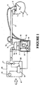
- a humidified Continuous Positive Airway Pressure (CPAP) system is shown in which a patient 1 is receiving humidified and pressurised gases through a patient interface 2 connected to a humidified gases transportation pathway or inspiratory conduit 3.
- delivery systems could also be VPAP (Variable Positive Airway Pressure) and BiPAP (Bi-level Positive Airway Pressure) or numerous other forms of respiratory therapy.
- Inspiratory conduit 3 is connected to the outlet 4 of a humidification chamber 5 which contains a volume of water 6.
- Inspiratory conduit 3 may contain heating means or heater wires (not shown) which heat the walls of the conduit to reduce condensation of humidified gases within the conduit.
- Humidification chamber 6 is preferably formed from a plastics material and may have a highly heat conductive base (for example an aluminium base) which is in direct contact with a heater plate 7 of humidifier 8.
- Humidifier 8 is provided with control means or electronic controller 9 which may comprise a microprocessor based controller executing computer software commands stored in associated memory.
- Controller 9 receives input from sources such as user input means or dial 10 through which a user of the device may, for example, set a predetermined required value (preset value) of humidity or temperature of the gases supplied to patient 1.
- the controller may also receive input from other sources, for example temperature and/or flow velocity sensors 11 and 12 through connector 13 and heater plate temperature sensor 14.
- controller 9 determines when (or to what level) to energise heater plate 7 to heat the water 6 within humidification chamber 5.
- inspiratory conduit 3 is characterised by a small cross section, having much reduced weight to conduits normally used in the art of breathing assistance.
- the internal diameter of the small cross section conduit is 4 to 6mm.
- the tubing is constructed of plastic or other compositions to allow the conduit to be relatively flexible.
- blower 15 preferably comprises a variable pressure compressor able to deliver high pressures at flow rates common with methods of breathing assistance eg: 50-80l/min.
- the compressor is capable of delivering 3 bar or 3000 cm H 2 O at its source.
- blower 15 is provided with variable pressure regulating means (eg: valve and fixed speed fan) or variable speed fan 21 which draws air or other gases through blower inlet 17.
- variable pressure regulating means eg: valve and fixed speed fan
- variable speed fan 21 which draws air or other gases through blower inlet 17.
- the speed of variable speed fan 21 is controlled by electronic controller 18 (or alternatively the function of controller 18 could carried out by controller 9) in response to inputs from controller 9 and a user set predetermined required value (preset value) of pressure or fan speed via dial 19.
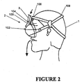
- the patient interface is shown in Figure 2 as a nasal mask.
- the mask includes a hollow body 102 with a manifold 103 connected to the inspiratory conduit 3.
- the mask 2 is positioned around the nose of the user 1 with the headgear 108 secured around the back of the head of the patient 1.
- the restraining force from the headgear 108 on the hollow body 102 and the forehead rest 106 ensures enough compressive force on the mask cushion 104, to provide an effective seal against the patient's face.
- the hollow body 102 is constructed of a relatively inflexible material for example, polycarbonate plastic. Such a material would provide the requisite rigidity as well as being transparent and a relatively good insulator.
- the expiratory gases can be expelled through a valve (not shown) in the mask, a further expiratory conduit (not shown), or any other such method as is known in the art.
- the manifold includes a valve body 200, and inlet passage 204 and an outlet vent 208. Gases from the conduit (3, Figure 1, 2) flow in through the inlet passage into the mask on inspiration and out from the mask through the outlet vent 208 on expiration.
- a sealing flap 202 is attached at one end 206 to the valve body, and seals over the outlet vent 208.
- the sealing flap 202 is biased closed against the outlet vent 208 by a venturi passage 210 in the inlet passage 204.
- the outlet of the venturi passage 210 is near the free end of the sealing flap 202.
- the flow in inlet passage 204 stops, removing the negative pressure from the venturi 210, allowing the sealing flap 202 to open.
- the expired gases then flow out the outlet vent 208.
- the venturi effect could be achieved using normal cross section respiratory conduit and providing a constriction at or about the venturi passage 210.
- the retaining of the flap in either position could equally be provided through any mechanical or electronic mechanism.
- the sealing flap could comprise a piezoelectric valve member.
- the present invention provides improved venting of expired gases over prior art masks.
- the use of the small cross section conduit maximises patient comfort and compliance.
- the small cross section makes buffering of expired gases, i.e. allowing them to flow partly back up the inspiratory conduit, less effective when compared with a larger cross section conduit
- the present invention outlet vent provides effective CO 2 washout, and reduced patient effort in breathing out, improving patient comfort.
Landscapes
- Health & Medical Sciences (AREA)
- Emergency Medicine (AREA)
- Pulmonology (AREA)
- Engineering & Computer Science (AREA)
- Anesthesiology (AREA)
- Biomedical Technology (AREA)
- Heart & Thoracic Surgery (AREA)
- Hematology (AREA)
- Life Sciences & Earth Sciences (AREA)
- Animal Behavior & Ethology (AREA)
- General Health & Medical Sciences (AREA)
- Public Health (AREA)
- Veterinary Medicine (AREA)
- Respiratory Apparatuses And Protective Means (AREA)
- Percussion Or Vibration Massage (AREA)
Abstract
Description
characterised in that said outlet means comprising:
Preferably said biasing means adapted to retain or actuate said valve member depending on the flow rate of gases through said internal passage.
Preferably said biasing means comprises a venturi in said internal passage including an outlet in use incident on said valve member.
Preferably said valve member comprises a flap of flexible material
Preferably said flexible material is a rubber composition.
Preferably said vent is a passage through said valve body from the interior of said patient interface to the exterior.
Preferably said patient interface is a nasal mask
Preferably said nasal mask comprising:
- restraining means attached to or around the head of said user,
- a body portion having an inlet receiving said supply of gases and an open section,
- sealing means attached to said body portion substantially contoured to the facial contours of said user,
- receiving means attached to said hard body which in use engages with said restraining means.
characterised in that said valve comprising:
- a valve body including an internal passage, in use at least a portion of said gases flowing through said internal passage,
- an external vent, and
- a valve member operatively connected to said valve body and having at least two configurations, a first configuration in use during inspiration of said patient substantially blocking said vent and a second configuration in use with said vent passing expired gases from said patient.
Preferably said biasing means adapted to retain or actuate said valve member depending on the flow rate of gases through said internal passage.
Preferably said biasing means comprises a venturi in said internal passage including an outlet in use incident on said valve member.
Preferably said valve member comprises a flap of flexible material
Preferably said flexible material is a rubber composition.
Preferably said vent is a passage through said valve body from the interior of said patient interface to the exterior.
In a third aspect the present invention consists in a system for delivering respiratory gases to a user
characterised in that said system comprising:
- a high pressure gases source,
- a low cross section conduit adapted to convey gases from said gases source, and
- a patient interface adapted to deliver gases from said conduit to said patient.
Claims (18)
- A device for delivering a supply of gases to a user comprising a patient interface, in use in fluid communication with said supply of gases, engaging with said user and thereby supplying said gases to said user; and outlet means being integrated with or in fluid communication with said patient interface,
characterised in that said outlet means comprising:a valve body including an internal passage, in use at least a portion of said gases flowing through said internal passage,an external vent, anda valve member operatively connected to said valve body and having at least two configurations, a first configuration in use during inspiration of said patient substantially blocking said vent and a second configuration in use with said vent passing expired gases from said patient. - A device as claimed in claim 1 further comprising biasing means adapted to retain or actuate said valve member between said first configuration and said second configuration.
- A device as claimed in claim 2 wherein said biasing means adapted to retain or actuate said valve member depending on the flow rate of gases through said internal passage.
- A device as claimed in claim 3 wherein said biasing means comprises a venturi in said internal passage including an outlet in use incident on said valve member.
- A device as claimed in any one of claims 1 to 4 wherein said valve member comprises a flap of flexible material
- A device as claimed in claim 5 wherein said flexible material is a rubber composition.
- A device as claimed in any one of claims 1 to 6 wherein said vent is a passage through said valve body from the interior of said patient interface to the exterior.
- A device as claimed in any one of claims 1 to 7 wherein said patient interface is a nasal mask.
- A device as claimed in claim 8 wherein said nasal mask comprising:restraining means attached to or around the head of said user,a body portion having an inlet receiving said supply of gases and an open section,sealing means attached to said body portion substantially contoured to the facial contours of said user,receiving means attached to said hard body which in use engages with said restraining means.
- A valve for use with a patient interface, for delivering breathing assistance in the form of gases to a patient, said valve being integrated with or in fluid communication with said patient interface,
characterised in that said valve comprising:a valve body including an internal passage, in use at least a portion of said gases flowing through said internal passage,an external vent, anda valve member operatively connected to said valve body and having at least two configurations, a first configuration in use during inspiration of said patient substantially blocking said vent and a second configuration in use with said vent passing expired gases from said patient - A valve as claimed in claim 10 further comprising biasing means adapted to retain or actuate said valve member between said first configuration and said second configuration.
- A valve as claimed in claim 11 wherein said biasing means adapted to retain or actuate said valve member depending on the flow rate of gases through said internal passage.
- A valve as claimed in claim 12 wherein said biasing means comprises a venturi in said internal passage including an outlet in use incident on said valve member.
- A valve as claimed in any one of claims 10 to 13 wherein said valve member comprises a flap of flexible material
- A valve as claimed in claim 14 wherein said flexible material is a rubber composition.
- A valve as claimed in any one of claims 10 to 15 wherein said vent is a passage through said valve body from the interior of said patient interface to the exterior.
- A system for delivering respiratory gases to a user
characterised in that said system comprising:a high pressure gases source,a low cross section conduit adapted to convey gases from said gases source, anda patient interface adapted to deliver gases from said conduit to said patient. - A system as claimed in claim 17 wherein said patient interface farther comprises a valve member operatively connected to said patient interface and having at least two configurations, a first configuration in use during inspiration of said patient substantially closed and a second configuration in use externally venting expired gases from said patient.
Applications Claiming Priority (2)
| Application Number | Priority Date | Filing Date | Title |
|---|---|---|---|
| NZ51264901 | 2001-06-27 | ||
| NZ51264901 | 2001-06-27 |
Publications (3)
| Publication Number | Publication Date |
|---|---|
| EP1275412A2 true EP1275412A2 (en) | 2003-01-15 |
| EP1275412A3 EP1275412A3 (en) | 2004-04-14 |
| EP1275412B1 EP1275412B1 (en) | 2008-04-16 |
Family
ID=19928529
Family Applications (1)
| Application Number | Title | Priority Date | Filing Date |
|---|---|---|---|
| EP02014184A Expired - Lifetime EP1275412B1 (en) | 2001-06-27 | 2002-06-25 | Exhalation valve for a nasal breathing mask |
Country Status (4)
| Country | Link |
|---|---|
| US (1) | US6923181B2 (en) |
| EP (1) | EP1275412B1 (en) |
| AT (1) | ATE392228T1 (en) |
| DE (1) | DE60226101T2 (en) |
Cited By (7)
| Publication number | Priority date | Publication date | Assignee | Title |
|---|---|---|---|---|
| WO2010076714A1 (en) * | 2008-12-30 | 2010-07-08 | Koninklijke Philips Electronics, N.V. | Mask and method for delivering a therapeutic breathable substance |
| DE112008003064T5 (en) | 2007-11-16 | 2010-12-09 | Fisher & Paykel Healthcare Ltd., East Tamaki | Nose olive with high volume bypass flow and method of use |
| DE112008002926T5 (en) | 2007-10-30 | 2010-12-09 | Fisher & Paykel Healthcare Ltd., East Tamaki | Blower unit with bypass ventilation holes |
| DE112010001830T5 (en) | 2009-04-29 | 2012-07-05 | Fisher & Paykel Healthcare Ltd. | Fan unit with improved pumping characteristics |
| EP1965849A4 (en) * | 2005-12-29 | 2013-07-24 | Olav Hustveit | Valve for a breathing apparatus |
| CN103684046A (en) * | 2013-12-13 | 2014-03-26 | 南京航空航天大学 | Human breath energy collecting device |
| EP3540281A1 (en) * | 2018-03-14 | 2019-09-18 | STMicroelectronics S.r.l. | Piezoelectric valve module, method for manufacturing the valve module, method for operating the valve module, and respiratory aid device including one or more valve modules |
Families Citing this family (52)
| Publication number | Priority date | Publication date | Assignee | Title |
|---|---|---|---|---|
| US5325892A (en) * | 1992-05-29 | 1994-07-05 | Minnesota Mining And Manufacturing Company | Unidirectional fluid valve |
| DE69312509T2 (en) * | 1992-05-29 | 1998-02-26 | Minnesota Mining And Mfg. Co., Saint Paul, Minn. | CHECK VALVE |
| US8997740B2 (en) | 2005-09-27 | 2015-04-07 | Ric Investments, Llc | Humidifier with back-flow prevention valve |
| US8701662B2 (en) * | 2005-09-27 | 2014-04-22 | Ric Investments, Llc | Humidifier with back-flow prevention valve |
| US7779841B2 (en) * | 2006-11-13 | 2010-08-24 | Carefusion 2200, Inc. | Respiratory therapy device and method |
| CA2682718C (en) * | 2007-04-02 | 2015-06-23 | Allegiance Corporation | High frequency oscillation respiratory therapy device |
| US8365731B2 (en) * | 2007-07-31 | 2013-02-05 | Ric Investments, Llc | Pressure reducing valve with flexible cuff |
| US8539951B1 (en) | 2008-05-27 | 2013-09-24 | Trudell Medical International | Oscillating positive respiratory pressure device |
| US8327849B2 (en) | 2008-10-28 | 2012-12-11 | Trudell Medical International | Oscillating positive expiratory pressure device |
| US9149589B2 (en) | 2009-02-23 | 2015-10-06 | Trudell Medical International | Method and device for performing orientation dependent oscillating positive expiratory pressure therapy |
| US8485179B1 (en) | 2009-02-23 | 2013-07-16 | Trudell Medical International | Oscillating positive expiratory pressure device |
| CA3207704A1 (en) | 2011-06-06 | 2012-12-13 | Trudell Medical International | Oscillating positive expiratory pressure device |
| US9038634B2 (en) | 2011-06-22 | 2015-05-26 | Breathe Technologies, Inc. | Ventilation mask with integrated piloted exhalation valve |
| US8844533B2 (en) | 2011-06-22 | 2014-09-30 | Breathe Technologies, Inc. | Ventilation mask with integrated piloted exhalation valve |
| US9616194B2 (en) | 2011-06-22 | 2017-04-11 | Breathe Technologies, Inc. | Ventilation mask with integrated piloted exhalation valve and method of ventilating a patient using the same |
| US9212673B2 (en) * | 2011-09-30 | 2015-12-15 | Carefusion 207, Inc. | Maintaining a water level in a humidification component |
| US10168046B2 (en) | 2011-09-30 | 2019-01-01 | Carefusion 207, Inc. | Non-metallic humidification component |
| US9492086B2 (en) | 2012-03-21 | 2016-11-15 | Fresca Medical, Inc. | Apparatus, systems, and methods for treating obstructive sleep apnea |
| US10307562B2 (en) | 2012-04-13 | 2019-06-04 | Fresca Medical, Inc. | Auto-feedback valve for a sleep apnea device |
| WO2013155349A1 (en) | 2012-04-13 | 2013-10-17 | Fresca Medical Inc. | Sleep apnea device |
| US10272226B2 (en) | 2012-04-13 | 2019-04-30 | Fresca Medical, Inc. | Auto-feedback valve for a sleep apnea device |
| WO2013157517A1 (en) * | 2012-04-16 | 2013-10-24 | 株式会社メトラン | Opening/closing device and respiratory assistance device |
| US9517315B2 (en) | 2012-11-30 | 2016-12-13 | Trudell Medical International | Oscillating positive expiratory pressure device |
| JP5358773B1 (en) * | 2013-02-21 | 2013-12-04 | 株式会社メトラン | Respiratory device |
| US10272224B2 (en) | 2013-07-12 | 2019-04-30 | Trudell Medical International | Huff cough simulation device |
| US9849257B2 (en) | 2013-08-22 | 2017-12-26 | Trudell Medical International | Oscillating positive respiratory pressure device |
| JP2015073830A (en) * | 2013-10-11 | 2015-04-20 | 株式会社メトラン | Opening and closing device and respiratory assistance device |
| US10363383B2 (en) | 2014-02-07 | 2019-07-30 | Trudell Medical International | Pressure indicator for an oscillating positive expiratory pressure device |
| CN112370631B (en) * | 2014-09-03 | 2025-12-30 | 费雪派克医疗保健有限公司 | Deterministically controlled humidification system |
| GB2546949B (en) * | 2014-11-25 | 2021-09-22 | Fisher & Paykel Healthcare Ltd | Substance delivery arrangement for gas therapy device |
| US10004872B1 (en) | 2015-03-06 | 2018-06-26 | D R Burton Healthcare, Llc | Positive expiratory pressure device having an oscillating valve |
| US11247015B2 (en) | 2015-03-24 | 2022-02-15 | Ventec Life Systems, Inc. | Ventilator with integrated oxygen production |
| US10245406B2 (en) | 2015-03-24 | 2019-04-02 | Ventec Life Systems, Inc. | Ventilator with integrated oxygen production |
| EP4134118B1 (en) | 2015-07-30 | 2024-11-27 | Trudell Medical International Inc. | Combined respiratory muscle training and oscillating positive expiratory pressure device |
| USD778429S1 (en) | 2015-09-02 | 2017-02-07 | Trudell Medical International | Respiratory treatment device |
| USD780906S1 (en) | 2015-09-02 | 2017-03-07 | Trudell Medical International | Respiratory treatment device |
| WO2017093966A1 (en) | 2015-12-04 | 2017-06-08 | Trudell Medical International | Huff cough simulation device |
| US10773049B2 (en) | 2016-06-21 | 2020-09-15 | Ventec Life Systems, Inc. | Cough-assist systems with humidifier bypass |
| USD842983S1 (en) | 2016-09-16 | 2019-03-12 | 3M Innovative Properties Company | Valve cover |
| USD843562S1 (en) | 2016-09-16 | 2019-03-19 | 3M Innovative Properties Company | Valve cover with diamond pattern |
| USD827811S1 (en) | 2016-09-16 | 2018-09-04 | 3M Innovative Properties Company | Valve cover |
| USD828546S1 (en) | 2016-09-16 | 2018-09-11 | 3M Innovative Properties Company | Valve cover with openings |
| USD827812S1 (en) | 2016-09-16 | 2018-09-04 | 3M Innovative Properties Company | Valve cover with openings |
| USD882758S1 (en) | 2016-09-16 | 2020-04-28 | 3M Innovative Properties Company | Valve cover |
| CA3036977A1 (en) | 2016-09-16 | 2018-03-22 | 3M Innovative Properties Company | Exhalation valve and respirator including same |
| USD849245S1 (en) | 2016-09-16 | 2019-05-21 | 3M Innovative Properties Company | Valve cover |
| USD900306S1 (en) | 2016-09-16 | 2020-10-27 | 3M Innovative Properties Company | Valve cover |
| WO2018203188A1 (en) | 2017-05-03 | 2018-11-08 | Trudell Medical International | Combined oscillating positive expiratory pressure therapy and huff cough simulation device |
| US10953278B2 (en) | 2018-02-02 | 2021-03-23 | Trudell Medical International | Oscillating positive expiratory pressure device |
| WO2019221852A1 (en) | 2018-05-13 | 2019-11-21 | Ahmad Samir Saleh | Portable medical ventilator system using portable oxygen concentrators |
| EP4240456A4 (en) | 2020-11-06 | 2024-09-04 | Ventec Life Systems, Inc. | RESPIRATORY THERAPY DATA MANAGEMENT SYSTEMS, DEVICES AND METHODS |
| US12440634B2 (en) | 2020-12-21 | 2025-10-14 | Ventec Life Systems, Inc. | Ventilator systems with integrated oxygen delivery, and associated devices and methods |
Family Cites Families (20)
| Publication number | Priority date | Publication date | Assignee | Title |
|---|---|---|---|---|
| CH345118A (en) * | 1955-11-05 | 1960-03-15 | Draeger Otto Heinrich Dr | Device for artificial respiration |
| DE1616422B1 (en) * | 1964-06-15 | 1971-11-18 | Laerdal A S | Valve for resuscitation apparatus |
| US3769973A (en) * | 1972-07-24 | 1973-11-06 | A Esbenshade | Intermittent positive pressure breathing apparatus |
| US3874378A (en) * | 1973-09-06 | 1975-04-01 | Globe Safety Products Inc | Combined resuscitator and inhalator apparatus |
| US4316458A (en) * | 1978-05-09 | 1982-02-23 | National Research Development Corporation | Patient ventilators |
| FR2535613B1 (en) * | 1982-11-05 | 1986-04-25 | Lejeune Seitz Ameline Labo | IMPROVEMENT IN RESPIRATORY VALVES |
| EP0549299B1 (en) * | 1991-12-20 | 2002-03-13 | Resmed Limited | Ventilator for continuous positive airway pressure breathing (CPAP) |
| ATE182801T1 (en) * | 1993-05-28 | 1999-08-15 | Pari Gmbh | MOUTHPIECE FOR INHALATION THERAPY DEVICES |
| US5655520A (en) * | 1993-08-23 | 1997-08-12 | Howe; Harvey James | Flexible valve for administering constant flow rates of medicine from a nebulizer |
| US5647355A (en) * | 1993-09-30 | 1997-07-15 | Respironics, Inc. | Automatic safety valve for respiratory equipment which is counter-balanced and self-adjusting |
| US5484270A (en) * | 1994-02-28 | 1996-01-16 | Carmeli Adahan | Pump particularly useful in respirator apparatus and exhalation valve assembly therefor |
| US5538000A (en) * | 1995-02-06 | 1996-07-23 | Hans Rudolph, Inc. | Airflow delivery system |
| US5662101A (en) * | 1995-12-07 | 1997-09-02 | Respironics, Inc. | Respiratory facial mask |
| AUPO301796A0 (en) * | 1996-10-16 | 1996-11-07 | Resmed Limited | A vent valve apparatus |
| US5896857A (en) * | 1996-12-20 | 1999-04-27 | Resmed Limited | Valve for use in a gas delivery system |
| US5791339A (en) * | 1997-03-13 | 1998-08-11 | Nellcor Puritan Bennettt Incorprated | Spring piloted safety valve with jet venturi bias |
| GB9827370D0 (en) * | 1998-01-16 | 1999-02-03 | Pari Gmbh | Mouthpiece for inhalation therapy units |
| AUPP794598A0 (en) * | 1998-12-24 | 1999-01-28 | Resmed Limited | An anti-asphyxia valve |
| DE19962110C2 (en) * | 1999-12-22 | 2003-06-12 | Pari Gmbh | Inhalation nebulizer with one-piece valve element |
| DE10105383C2 (en) * | 2001-02-06 | 2003-06-05 | Heptec Gmbh | Anti-snoring device |
-
2002
- 2002-06-25 EP EP02014184A patent/EP1275412B1/en not_active Expired - Lifetime
- 2002-06-25 DE DE60226101T patent/DE60226101T2/en not_active Expired - Lifetime
- 2002-06-25 AT AT02014184T patent/ATE392228T1/en not_active IP Right Cessation
- 2002-06-26 US US10/180,714 patent/US6923181B2/en not_active Expired - Lifetime
Cited By (14)
| Publication number | Priority date | Publication date | Assignee | Title |
|---|---|---|---|---|
| EP1965849A4 (en) * | 2005-12-29 | 2013-07-24 | Olav Hustveit | Valve for a breathing apparatus |
| DE112008002926T5 (en) | 2007-10-30 | 2010-12-09 | Fisher & Paykel Healthcare Ltd., East Tamaki | Blower unit with bypass ventilation holes |
| US9192735B2 (en) | 2007-10-30 | 2015-11-24 | Fisher & Paykel Healthcare Limited | Fan unit with bypass vent holes |
| US10537694B2 (en) | 2007-11-16 | 2020-01-21 | Fisher & Paykel Healthcare Limited | Nasal pillows with high volume bypass flow and method of using same |
| DE112008003064T5 (en) | 2007-11-16 | 2010-12-09 | Fisher & Paykel Healthcare Ltd., East Tamaki | Nose olive with high volume bypass flow and method of use |
| US9205215B2 (en) | 2007-11-16 | 2015-12-08 | Fisher & Paykel Health Limited | Nasal pillows with high volume bypass flow and method of using same |
| CN102271742A (en) * | 2008-12-30 | 2011-12-07 | 皇家飞利浦电子股份有限公司 | Mask and method for delivering a therapeutic breathable substance |
| WO2010076714A1 (en) * | 2008-12-30 | 2010-07-08 | Koninklijke Philips Electronics, N.V. | Mask and method for delivering a therapeutic breathable substance |
| DE112010001830T5 (en) | 2009-04-29 | 2012-07-05 | Fisher & Paykel Healthcare Ltd. | Fan unit with improved pumping characteristics |
| CN103684046A (en) * | 2013-12-13 | 2014-03-26 | 南京航空航天大学 | Human breath energy collecting device |
| CN103684046B (en) * | 2013-12-13 | 2016-03-02 | 南京航空航天大学 | A kind of human body respiration energy collecting device |
| EP3540281A1 (en) * | 2018-03-14 | 2019-09-18 | STMicroelectronics S.r.l. | Piezoelectric valve module, method for manufacturing the valve module, method for operating the valve module, and respiratory aid device including one or more valve modules |
| US20190285196A1 (en) * | 2018-03-14 | 2019-09-19 | Stmicroelectronics S.R.L. | Piezoelectric valve module, method for manufacturing the valve module, method for operating the valve module, and respiratory aid device including one or more of the valve modules |
| US10941880B2 (en) | 2018-03-14 | 2021-03-09 | Stmicroelectronics S.R.L. | Piezoelectric valve module, method for manufacturing the valve module, method for operating the valve module, and respiratory aid device including one or more of the valve modules |
Also Published As
| Publication number | Publication date |
|---|---|
| US6923181B2 (en) | 2005-08-02 |
| EP1275412A3 (en) | 2004-04-14 |
| DE60226101T2 (en) | 2009-06-25 |
| EP1275412B1 (en) | 2008-04-16 |
| US20030000531A1 (en) | 2003-01-02 |
| ATE392228T1 (en) | 2008-05-15 |
| DE60226101D1 (en) | 2008-05-29 |
Similar Documents
| Publication | Publication Date | Title |
|---|---|---|
| US6923181B2 (en) | Nasal mask | |
| US7308895B2 (en) | Breathing assistance apparatus | |
| US20210228829A1 (en) | Breathing assistance apparatus | |
| EP3838323B1 (en) | Respiratory mask with gas washout vent | |
| EP1163923B1 (en) | A nasal mask | |
| CA2370995C (en) | Breathing assistance apparatus | |
| EP1302212A2 (en) | Forehead support for a facial mask | |
| US7059328B2 (en) | Ventilation interface for sleep apnea therapy | |
| US20030000533A1 (en) | Breathing assistance apparatus | |
| US10463828B2 (en) | Breathing assistance apparatus | |
| HK40033117B (en) | Breathing assistance apparatus | |
| HK40033117A (en) | Breathing assistance apparatus | |
| NZ508219A (en) | Mask with gas supply, typically face or nasal mask, with sliding strap | |
| AU1543202A (en) | Breathing assistance apparatus |
Legal Events
| Date | Code | Title | Description |
|---|---|---|---|
| PUAI | Public reference made under article 153(3) epc to a published international application that has entered the european phase |
Free format text: ORIGINAL CODE: 0009012 |
|
| AK | Designated contracting states |
Kind code of ref document: A2 Designated state(s): AT BE CH CY DE DK ES FI FR GB GR IE IT LI LU MC NL PT SE TR |
|
| AX | Request for extension of the european patent |
Free format text: AL;LT;LV;MK;RO;SI |
|
| RIC1 | Information provided on ipc code assigned before grant |
Ipc: 7A 61M 16/16 B Ipc: 7A 61M 16/06 B Ipc: 7A 61M 16/20 A Ipc: 7A 61M 16/10 B |
|
| PUAL | Search report despatched |
Free format text: ORIGINAL CODE: 0009013 |
|
| AK | Designated contracting states |
Kind code of ref document: A3 Designated state(s): AT BE CH CY DE DK ES FI FR GB GR IE IT LI LU MC NL PT SE TR |
|
| AX | Request for extension of the european patent |
Extension state: AL LT LV MK RO SI |
|
| 17P | Request for examination filed |
Effective date: 20040715 |
|
| AKX | Designation fees paid |
Designated state(s): AT BE CH CY DE DK ES FI FR GB GR IE IT LI LU MC NL PT SE TR |
|
| 17Q | First examination report despatched |
Effective date: 20050307 |
|
| 17Q | First examination report despatched |
Effective date: 20050307 |
|
| RIC1 | Information provided on ipc code assigned before grant |
Ipc: A61M 16/06 20060101ALI20070725BHEP Ipc: A61M 16/20 20060101AFI20070725BHEP |
|
| RTI1 | Title (correction) |
Free format text: EXHALATION VALVE FOR A NASAL BREATHING MASK |
|
| GRAP | Despatch of communication of intention to grant a patent |
Free format text: ORIGINAL CODE: EPIDOSNIGR1 |
|
| GRAS | Grant fee paid |
Free format text: ORIGINAL CODE: EPIDOSNIGR3 |
|
| GRAA | (expected) grant |
Free format text: ORIGINAL CODE: 0009210 |
|
| AK | Designated contracting states |
Kind code of ref document: B1 Designated state(s): AT BE CH CY DE DK ES FI FR GB GR IE IT LI LU MC NL PT SE TR |
|
| REG | Reference to a national code |
Ref country code: CH Ref legal event code: EP |
|
| REG | Reference to a national code |
Ref country code: IE Ref legal event code: FG4D |
|
| REF | Corresponds to: |
Ref document number: 60226101 Country of ref document: DE Date of ref document: 20080529 Kind code of ref document: P |
|
| NLV1 | Nl: lapsed or annulled due to failure to fulfill the requirements of art. 29p and 29m of the patents act | ||
| PG25 | Lapsed in a contracting state [announced via postgrant information from national office to epo] |
Ref country code: PT Free format text: LAPSE BECAUSE OF FAILURE TO SUBMIT A TRANSLATION OF THE DESCRIPTION OR TO PAY THE FEE WITHIN THE PRESCRIBED TIME-LIMIT Effective date: 20080916 Ref country code: ES Free format text: LAPSE BECAUSE OF FAILURE TO SUBMIT A TRANSLATION OF THE DESCRIPTION OR TO PAY THE FEE WITHIN THE PRESCRIBED TIME-LIMIT Effective date: 20080727 Ref country code: FI Free format text: LAPSE BECAUSE OF FAILURE TO SUBMIT A TRANSLATION OF THE DESCRIPTION OR TO PAY THE FEE WITHIN THE PRESCRIBED TIME-LIMIT Effective date: 20080416 Ref country code: NL Free format text: LAPSE BECAUSE OF FAILURE TO SUBMIT A TRANSLATION OF THE DESCRIPTION OR TO PAY THE FEE WITHIN THE PRESCRIBED TIME-LIMIT Effective date: 20080416 |
|
| PG25 | Lapsed in a contracting state [announced via postgrant information from national office to epo] |
Ref country code: AT Free format text: LAPSE BECAUSE OF FAILURE TO SUBMIT A TRANSLATION OF THE DESCRIPTION OR TO PAY THE FEE WITHIN THE PRESCRIBED TIME-LIMIT Effective date: 20080416 |
|
| ET | Fr: translation filed | ||
| PG25 | Lapsed in a contracting state [announced via postgrant information from national office to epo] |
Ref country code: MC Free format text: LAPSE BECAUSE OF NON-PAYMENT OF DUE FEES Effective date: 20080630 Ref country code: DK Free format text: LAPSE BECAUSE OF FAILURE TO SUBMIT A TRANSLATION OF THE DESCRIPTION OR TO PAY THE FEE WITHIN THE PRESCRIBED TIME-LIMIT Effective date: 20080416 Ref country code: SE Free format text: LAPSE BECAUSE OF FAILURE TO SUBMIT A TRANSLATION OF THE DESCRIPTION OR TO PAY THE FEE WITHIN THE PRESCRIBED TIME-LIMIT Effective date: 20080716 |
|
| REG | Reference to a national code |
Ref country code: CH Ref legal event code: PL |
|
| PLBE | No opposition filed within time limit |
Free format text: ORIGINAL CODE: 0009261 |
|
| STAA | Information on the status of an ep patent application or granted ep patent |
Free format text: STATUS: NO OPPOSITION FILED WITHIN TIME LIMIT |
|
| PG25 | Lapsed in a contracting state [announced via postgrant information from national office to epo] |
Ref country code: BE Free format text: LAPSE BECAUSE OF FAILURE TO SUBMIT A TRANSLATION OF THE DESCRIPTION OR TO PAY THE FEE WITHIN THE PRESCRIBED TIME-LIMIT Effective date: 20080416 |
|
| 26N | No opposition filed |
Effective date: 20090119 |
|
| GBPC | Gb: european patent ceased through non-payment of renewal fee |
Effective date: 20080716 |
|
| PG25 | Lapsed in a contracting state [announced via postgrant information from national office to epo] |
Ref country code: IE Free format text: LAPSE BECAUSE OF NON-PAYMENT OF DUE FEES Effective date: 20080625 |
|
| PG25 | Lapsed in a contracting state [announced via postgrant information from national office to epo] |
Ref country code: GB Free format text: LAPSE BECAUSE OF NON-PAYMENT OF DUE FEES Effective date: 20080716 Ref country code: LI Free format text: LAPSE BECAUSE OF NON-PAYMENT OF DUE FEES Effective date: 20080630 Ref country code: CH Free format text: LAPSE BECAUSE OF NON-PAYMENT OF DUE FEES Effective date: 20080630 |
|
| PG25 | Lapsed in a contracting state [announced via postgrant information from national office to epo] |
Ref country code: IT Free format text: LAPSE BECAUSE OF FAILURE TO SUBMIT A TRANSLATION OF THE DESCRIPTION OR TO PAY THE FEE WITHIN THE PRESCRIBED TIME-LIMIT Effective date: 20080416 |
|
| PG25 | Lapsed in a contracting state [announced via postgrant information from national office to epo] |
Ref country code: CY Free format text: LAPSE BECAUSE OF FAILURE TO SUBMIT A TRANSLATION OF THE DESCRIPTION OR TO PAY THE FEE WITHIN THE PRESCRIBED TIME-LIMIT Effective date: 20080416 |
|
| PG25 | Lapsed in a contracting state [announced via postgrant information from national office to epo] |
Ref country code: LU Free format text: LAPSE BECAUSE OF NON-PAYMENT OF DUE FEES Effective date: 20080625 |
|
| PG25 | Lapsed in a contracting state [announced via postgrant information from national office to epo] |
Ref country code: TR Free format text: LAPSE BECAUSE OF FAILURE TO SUBMIT A TRANSLATION OF THE DESCRIPTION OR TO PAY THE FEE WITHIN THE PRESCRIBED TIME-LIMIT Effective date: 20080416 |
|
| PG25 | Lapsed in a contracting state [announced via postgrant information from national office to epo] |
Ref country code: GR Free format text: LAPSE BECAUSE OF FAILURE TO SUBMIT A TRANSLATION OF THE DESCRIPTION OR TO PAY THE FEE WITHIN THE PRESCRIBED TIME-LIMIT Effective date: 20080717 |
|
| REG | Reference to a national code |
Ref country code: FR Ref legal event code: PLFP Year of fee payment: 15 |
|
| REG | Reference to a national code |
Ref country code: FR Ref legal event code: PLFP Year of fee payment: 16 |
|
| REG | Reference to a national code |
Ref country code: FR Ref legal event code: PLFP Year of fee payment: 17 |
|
| PGFP | Annual fee paid to national office [announced via postgrant information from national office to epo] |
Ref country code: FR Payment date: 20190625 Year of fee payment: 18 |
|
| PGFP | Annual fee paid to national office [announced via postgrant information from national office to epo] |
Ref country code: DE Payment date: 20190830 Year of fee payment: 18 |
|
| REG | Reference to a national code |
Ref country code: DE Ref legal event code: R119 Ref document number: 60226101 Country of ref document: DE |
|
| PG25 | Lapsed in a contracting state [announced via postgrant information from national office to epo] |
Ref country code: FR Free format text: LAPSE BECAUSE OF NON-PAYMENT OF DUE FEES Effective date: 20200630 |
|
| PG25 | Lapsed in a contracting state [announced via postgrant information from national office to epo] |
Ref country code: DE Free format text: LAPSE BECAUSE OF NON-PAYMENT OF DUE FEES Effective date: 20210101 |