EP3838323B1 - Respiratory mask with gas washout vent - Google Patents
Respiratory mask with gas washout vent Download PDFInfo
- Publication number
- EP3838323B1 EP3838323B1 EP21156388.7A EP21156388A EP3838323B1 EP 3838323 B1 EP3838323 B1 EP 3838323B1 EP 21156388 A EP21156388 A EP 21156388A EP 3838323 B1 EP3838323 B1 EP 3838323B1
- Authority
- EP
- European Patent Office
- Prior art keywords
- outlet member
- mask
- hollow body
- recess
- outlet
- Prior art date
- Legal status (The legal status is an assumption and is not a legal conclusion. Google has not performed a legal analysis and makes no representation as to the accuracy of the status listed.)
- Active
Links
- 230000000241 respiratory effect Effects 0.000 title description 9
- 239000007789 gas Substances 0.000 claims description 44
- 230000003434 inspiratory effect Effects 0.000 claims description 10
- 239000000463 material Substances 0.000 claims description 4
- 238000000034 method Methods 0.000 claims description 4
- 239000004033 plastic Substances 0.000 claims description 4
- 229920003023 plastic Polymers 0.000 claims description 4
- 238000004026 adhesive bonding Methods 0.000 claims description 3
- 238000003466 welding Methods 0.000 claims description 3
- 230000000295 complement effect Effects 0.000 claims description 2
- 238000002347 injection Methods 0.000 claims description 2
- 239000007924 injection Substances 0.000 claims description 2
- 239000004417 polycarbonate Substances 0.000 claims description 2
- 229920000515 polycarbonate Polymers 0.000 claims description 2
- 239000012530 fluid Substances 0.000 claims 1
- 239000003570 air Substances 0.000 description 9
- XLYOFNOQVPJJNP-UHFFFAOYSA-N water Substances O XLYOFNOQVPJJNP-UHFFFAOYSA-N 0.000 description 5
- 238000011513 continuous positive airway pressure therapy Methods 0.000 description 3
- 238000002644 respiratory therapy Methods 0.000 description 3
- CURLTUGMZLYLDI-UHFFFAOYSA-N Carbon dioxide Chemical compound O=C=O CURLTUGMZLYLDI-UHFFFAOYSA-N 0.000 description 2
- 230000008901 benefit Effects 0.000 description 2
- 238000004519 manufacturing process Methods 0.000 description 2
- 208000001797 obstructive sleep apnea Diseases 0.000 description 2
- 230000029058 respiratory gaseous exchange Effects 0.000 description 2
- 230000004044 response Effects 0.000 description 2
- 238000007789 sealing Methods 0.000 description 2
- 230000001225 therapeutic effect Effects 0.000 description 2
- XAGFODPZIPBFFR-UHFFFAOYSA-N aluminium Chemical compound [Al] XAGFODPZIPBFFR-UHFFFAOYSA-N 0.000 description 1
- 229910052782 aluminium Inorganic materials 0.000 description 1
- 239000004411 aluminium Substances 0.000 description 1
- 239000012080 ambient air Substances 0.000 description 1
- 238000013459 approach Methods 0.000 description 1
- 210000001124 body fluid Anatomy 0.000 description 1
- 229910002092 carbon dioxide Inorganic materials 0.000 description 1
- 239000001569 carbon dioxide Substances 0.000 description 1
- 230000005494 condensation Effects 0.000 description 1
- 238000009833 condensation Methods 0.000 description 1
- 230000001419 dependent effect Effects 0.000 description 1
- 238000010586 diagram Methods 0.000 description 1
- 229920001971 elastomer Polymers 0.000 description 1
- 239000000806 elastomer Substances 0.000 description 1
- -1 for example Substances 0.000 description 1
- 230000006870 function Effects 0.000 description 1
- 238000010438 heat treatment Methods 0.000 description 1
- 239000012212 insulator Substances 0.000 description 1
- 230000007794 irritation Effects 0.000 description 1
- 230000007246 mechanism Effects 0.000 description 1
- 238000005065 mining Methods 0.000 description 1
- 238000000465 moulding Methods 0.000 description 1
- 230000037361 pathway Effects 0.000 description 1
- 230000001105 regulatory effect Effects 0.000 description 1
- 230000000452 restraining effect Effects 0.000 description 1
- 229910052710 silicon Inorganic materials 0.000 description 1
- 239000010703 silicon Substances 0.000 description 1
Images


Classifications
-
- A—HUMAN NECESSITIES
- A61—MEDICAL OR VETERINARY SCIENCE; HYGIENE
- A61M—DEVICES FOR INTRODUCING MEDIA INTO, OR ONTO, THE BODY; DEVICES FOR TRANSDUCING BODY MEDIA OR FOR TAKING MEDIA FROM THE BODY; DEVICES FOR PRODUCING OR ENDING SLEEP OR STUPOR
- A61M16/00—Devices for influencing the respiratory system of patients by gas treatment, e.g. mouth-to-mouth respiration; Tracheal tubes
- A61M16/06—Respiratory or anaesthetic masks
-
- A—HUMAN NECESSITIES
- A61—MEDICAL OR VETERINARY SCIENCE; HYGIENE
- A61M—DEVICES FOR INTRODUCING MEDIA INTO, OR ONTO, THE BODY; DEVICES FOR TRANSDUCING BODY MEDIA OR FOR TAKING MEDIA FROM THE BODY; DEVICES FOR PRODUCING OR ENDING SLEEP OR STUPOR
- A61M16/00—Devices for influencing the respiratory system of patients by gas treatment, e.g. mouth-to-mouth respiration; Tracheal tubes
- A61M16/021—Devices for influencing the respiratory system of patients by gas treatment, e.g. mouth-to-mouth respiration; Tracheal tubes operated by electrical means
- A61M16/022—Control means therefor
- A61M16/024—Control means therefor including calculation means, e.g. using a processor
-
- A—HUMAN NECESSITIES
- A61—MEDICAL OR VETERINARY SCIENCE; HYGIENE
- A61M—DEVICES FOR INTRODUCING MEDIA INTO, OR ONTO, THE BODY; DEVICES FOR TRANSDUCING BODY MEDIA OR FOR TAKING MEDIA FROM THE BODY; DEVICES FOR PRODUCING OR ENDING SLEEP OR STUPOR
- A61M16/00—Devices for influencing the respiratory system of patients by gas treatment, e.g. mouth-to-mouth respiration; Tracheal tubes
- A61M16/06—Respiratory or anaesthetic masks
- A61M16/0605—Means for improving the adaptation of the mask to the patient
- A61M16/0616—Means for improving the adaptation of the mask to the patient with face sealing means comprising a flap or membrane projecting inwards, such that sealing increases with increasing inhalation gas pressure
- A61M16/0622—Means for improving the adaptation of the mask to the patient with face sealing means comprising a flap or membrane projecting inwards, such that sealing increases with increasing inhalation gas pressure having an underlying cushion
-
- A—HUMAN NECESSITIES
- A61—MEDICAL OR VETERINARY SCIENCE; HYGIENE
- A61M—DEVICES FOR INTRODUCING MEDIA INTO, OR ONTO, THE BODY; DEVICES FOR TRANSDUCING BODY MEDIA OR FOR TAKING MEDIA FROM THE BODY; DEVICES FOR PRODUCING OR ENDING SLEEP OR STUPOR
- A61M16/00—Devices for influencing the respiratory system of patients by gas treatment, e.g. mouth-to-mouth respiration; Tracheal tubes
- A61M16/20—Valves specially adapted to medical respiratory devices
- A61M16/208—Non-controlled one-way valves, e.g. exhalation, check, pop-off non-rebreathing valves
-
- A—HUMAN NECESSITIES
- A61—MEDICAL OR VETERINARY SCIENCE; HYGIENE
- A61M—DEVICES FOR INTRODUCING MEDIA INTO, OR ONTO, THE BODY; DEVICES FOR TRANSDUCING BODY MEDIA OR FOR TAKING MEDIA FROM THE BODY; DEVICES FOR PRODUCING OR ENDING SLEEP OR STUPOR
- A61M16/00—Devices for influencing the respiratory system of patients by gas treatment, e.g. mouth-to-mouth respiration; Tracheal tubes
- A61M16/06—Respiratory or anaesthetic masks
- A61M16/0605—Means for improving the adaptation of the mask to the patient
- A61M16/0633—Means for improving the adaptation of the mask to the patient with forehead support
-
- A—HUMAN NECESSITIES
- A61—MEDICAL OR VETERINARY SCIENCE; HYGIENE
- A61M—DEVICES FOR INTRODUCING MEDIA INTO, OR ONTO, THE BODY; DEVICES FOR TRANSDUCING BODY MEDIA OR FOR TAKING MEDIA FROM THE BODY; DEVICES FOR PRODUCING OR ENDING SLEEP OR STUPOR
- A61M16/00—Devices for influencing the respiratory system of patients by gas treatment, e.g. mouth-to-mouth respiration; Tracheal tubes
- A61M16/06—Respiratory or anaesthetic masks
- A61M16/0683—Holding devices therefor
-
- A—HUMAN NECESSITIES
- A61—MEDICAL OR VETERINARY SCIENCE; HYGIENE
- A61M—DEVICES FOR INTRODUCING MEDIA INTO, OR ONTO, THE BODY; DEVICES FOR TRANSDUCING BODY MEDIA OR FOR TAKING MEDIA FROM THE BODY; DEVICES FOR PRODUCING OR ENDING SLEEP OR STUPOR
- A61M16/00—Devices for influencing the respiratory system of patients by gas treatment, e.g. mouth-to-mouth respiration; Tracheal tubes
- A61M16/08—Bellows; Connecting tubes ; Water traps; Patient circuits
- A61M16/0816—Joints or connectors
-
- A—HUMAN NECESSITIES
- A61—MEDICAL OR VETERINARY SCIENCE; HYGIENE
- A61M—DEVICES FOR INTRODUCING MEDIA INTO, OR ONTO, THE BODY; DEVICES FOR TRANSDUCING BODY MEDIA OR FOR TAKING MEDIA FROM THE BODY; DEVICES FOR PRODUCING OR ENDING SLEEP OR STUPOR
- A61M16/00—Devices for influencing the respiratory system of patients by gas treatment, e.g. mouth-to-mouth respiration; Tracheal tubes
- A61M16/06—Respiratory or anaesthetic masks
- A61M2016/0661—Respiratory or anaesthetic masks with customised shape
-
- A—HUMAN NECESSITIES
- A61—MEDICAL OR VETERINARY SCIENCE; HYGIENE
- A61M—DEVICES FOR INTRODUCING MEDIA INTO, OR ONTO, THE BODY; DEVICES FOR TRANSDUCING BODY MEDIA OR FOR TAKING MEDIA FROM THE BODY; DEVICES FOR PRODUCING OR ENDING SLEEP OR STUPOR
- A61M39/00—Tubes, tube connectors, tube couplings, valves, access sites or the like, specially adapted for medical use
- A61M39/22—Valves or arrangement of valves
- A61M39/24—Check- or non-return valves
- A61M2039/2426—Slit valve
-
- A—HUMAN NECESSITIES
- A61—MEDICAL OR VETERINARY SCIENCE; HYGIENE
- A61M—DEVICES FOR INTRODUCING MEDIA INTO, OR ONTO, THE BODY; DEVICES FOR TRANSDUCING BODY MEDIA OR FOR TAKING MEDIA FROM THE BODY; DEVICES FOR PRODUCING OR ENDING SLEEP OR STUPOR
- A61M2202/00—Special media to be introduced, removed or treated
- A61M2202/02—Gases
- A61M2202/0225—Carbon oxides, e.g. Carbon dioxide
-
- A—HUMAN NECESSITIES
- A61—MEDICAL OR VETERINARY SCIENCE; HYGIENE
- A61M—DEVICES FOR INTRODUCING MEDIA INTO, OR ONTO, THE BODY; DEVICES FOR TRANSDUCING BODY MEDIA OR FOR TAKING MEDIA FROM THE BODY; DEVICES FOR PRODUCING OR ENDING SLEEP OR STUPOR
- A61M2205/00—General characteristics of the apparatus
- A61M2205/42—Reducing noise
Definitions
- This invention relates to the delivery of respiratory gases, and in particular to patient interfaces for providing gases to patients requiring respiratory therapy.
- respiration devices there are well known a variety of respiratory masks which cover the nose and/or mouth of a human user in order to provide a continuous seal around the nasal and/or oral areas of the face such that gas may be provided at positive pressure within the mask for consumption by the user.
- the uses for such masks range from high altitude breathing (i.e., aviation applications) to mining and fire fighting applications, to various medical diagnostic and therapeutic applications.
- a vent for washout of the bias flow or expired gases to the atmosphere there is generally provided in the art a vent for washout of the bias flow or expired gases to the atmosphere.
- a vent may be provided for example, as part of the mask, or in the case of some respirators where a further conduit carries the expiratory gases, at the respirator.
- the washout of gas from the mask is essential to ensure that carbon dioxide build up does not occur over the range of flow rates.
- typical flow rates in CPAP treatment usually between 4cm H 2 O to 20cm H 2 O, prior art attempts at such vents have resulted in excessive noise causing irritation to the user and concentrated flows of gases irritating any bed partners.
- WO 00/78381 A1 discloses a respiratory mask, or a connector for a respiratory mask and a supply conduit, having a gas washout vent passage.
- the outlet interior surface forms a smooth prolongation with an adjacent exterior surface of the mask, or the connector.
- United States Patent No. 6,584,977 B1 discloses a combined patient interface and integrated exhaust assembly that passes a controlled flow of gas from an interior of a patient interface to ambient atmosphere at a predetermined flow rate irrespective of variations of pressure in the interior of the patient interface device relative to ambient atmosphere.
- United States Patent No. 4,811,730 discloses a resuscitation mask which has a base member with an inflatable bladder about its periphery which seals against the face of the patient upon initial flow of air into the mask from the rescuer.
- a one-way valve and filter precludes flow of air and bodily fluids from the patient to the mouthpiece, and diverts exhaled air to the atmosphere about the mask.
- EP 1 163 923 A2 discloses a patient interface with an outlet vent including a main vent which is diffused and muffled and a higher resistance vent provided in case the main vent is blocked.
- WO 02/051486 A1 discloses a flow regulation vent including a fixed portion adapted to engage a gas supply conduit and a spring force biased movable portion connected by a hinge to the fixed portion.
- WO 01/62326 A1 discloses a sealing lip device for a respiratory mask, a respiratory mask per se and a method and mould for producing the same.
- the present invention provides a device for delivering a supply of gases to a user as defined in claim 1.
- Preferred embodiments of the present invention are defined in the dependent claims.
- the present invention provides improvements in the field of CPAP therapy.
- a mask with a gas outlet which is quieter and has a more diffused outlet flow.
- manufacture of the gas outlet on a mask is simpler; it does not suffer to the same extent from excessive manufacturing faults.
- the mask as described in the preferred embodiment of the present invention can be used in respiratory care generally or with a ventilator but will now be described below with reference to use in a humidified CPAP system.
- the outlet vent described is equally applicable to all forms of patent interface.
- the outlet vent described can be used with various forms of mask, it is not limited to use with full face masks, but is described below with reference to full face masks.
- the full face mask of the present invention also has the added benefit of extending under the chin of the patient in use, and as such patients do not require a chin strap, as is the case with some prior art masks.
- a humidified Continuous Positive Airway Pressure (CPAP) system in which a patient 1 is receiving humidified and pressurised gases through a patient interface, for example a full face mask 2 (as shown in Figure 2 ) or other appropriate types of patient interfaces, such as nasal masks.
- the patient interface 2 is connected to a humidified gases transportation pathway or inspiratory conduit 3.
- delivery systems could also be VPAP (Variable Positive Airway Pressure) and BiPAP (Bi-level Positive Airway Pressure) or numerous other forms of respiratory therapy.
- Inspiratory conduit 3 is connected to the outlet 4 of a humidification chamber 5 which contains a volume of water 6.
- Inspiratory conduit 3 may contain heating means or heater wires (not shown) which heat the walls of the conduit to reduce condensation of humidified gases within the conduit.
- Humidification chamber 6 is preferably formed from a plastics material and may have a highly heat conductive base (for example an aluminium base) which is in direct contact with a heater plate 7 of humidifier 8.
- Humidifier 8 is provided with control means or electronic controller 9 which may comprise a microprocessor based controller executing computer software commands stored in associated memory.
- Controller 9 receives input from sources such as user input means or dial 10 through which a user of the device may, for example, set a predetermined required value (preset value) of humidity or temperature of the gases supplied to patient 1.
- the controller may also receive input from other sources, for example temperature and/or flow velocity sensors 11 and 12 through connector 13 and heater plate temperature sensor 14.
- controller 9 determines when (or to what level) to energise heater plate 7 to heat the water 6 within humidification chamber 5.
- water vapour begins to fill the volume of the chamber above the water's surface and is passed out of the humidification chamber 5 outlet 4 with the flow of gases (for example air) provided from a gases supply means or blower 15 which enters the chamber through inlet 16.
- gases for example air
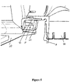
- Exhaled gases from the patient's mouth exit through vents in the mask and are passed to ambient surroundings, as shown in Figure 1 .
- Blower 15 is provided with variable pressure regulating means or variable speed fan 21 which draws air or other gases through blower inlet 17.
- the speed of variable speed fan 21 is controlled by electronic controller 18 (or alternatively the function of controller 18 could carried out by controller 9) in response to inputs from controller 9 and a user set predetermined required value (preset value) of pressure or fan speed via dial 19.
- the mask 2 includes a hollow body 30 and mask cushion 33.
- the mask cushion 33 resides within the hollow body 30 and provides cushioning of the mask 2 or the patient's face.
- the hollow body and mask cushion are shown in Figures 1 and 13 as extending under the patients chin, in particular, in the area indicated as 55. The extension under the chin of the cushion 33 provides a good seal and renders unnecessary a chin strap.
- the hollow body 30 has an integrally formed recess 31.
- the recess 31 preferably extends longitudinally along and over the width of the mask body 30 but may not extend the full width of the mask as shown in Figure 2 . Further the recess 31 may not be a longitudinal recess but lateral or other orientation.
- An outlet member or insert 32 is fittable about or in the recess.
- the insert 32 substantially covers the whole of the recess 31.
- the recess 31 and insert 32 each have complementary circular apertures 34, 35 that form an inspiratory inlet 36 when the insert 32 is placed in the recess 30.
- the inlet 36 is capable of being connected to the tubing that forms the inspiratory conduit 3 (as shown on Figure 1 ).
- the mask 2 is positioned around the nose and mouth of the user 1 and headgear (not shown) may be secured around the back of the head of the patient 1 to assist in the maintaining of the mask on the patient's face.
- the restraining force from the headgear on the hollow body 30 ensures enough compressive force on the mask cushion 33 to provide an effective seal against the patient's face.
- the hollow body 30 and insert 32 are injection moulded in a relatively inflexible material, for example, polycarbonate plastic. Such a material would provide the requisite rigidity for the mask as well as being transparent and a relatively good insulator.
- slots 37, 38 are created between the mask shell 30 and insert 32. These slots 37, 38 act as expiratory vents for gases expired in use into the mask by the patient wearing the mask.
- the insert 32 is removable, but in other forms the insert is welded in place to prevent removal.
- the insert 32 is curved to follow the contours of the mask shell 30 and has upper and lower sides 39, 40 that taper down towards the left and right sides 41, 42.
- Two elongated recesses 43, 44 are formed on the insert's upper and lower sides 39, 40.
- the recesses 43, 44 are shown as being formed in the middle section of the insert 32 near to the inspiratory aperture 34 and do not extend over the full length of the upper and lower sides 39, 40. In other forms the recesses (that form the expiratory vents) may extend along the full length of the upper and lower sides of the insert.
- a number of walls are provided that the insert rests against.
- a lower internal wall 48 having side walls 49, 50 extending upwards from it is formed at the lower edge of the recess 31.
- the lower outlet vent 37 is actually formed between the boundary of the lower wall 48 and the lower side of the insert 32.
- Upper internal sideways walls 51, 52 are also formed in the recess 31. These provide further support and each of the side walls 49, 50, 51, 52 fit within slots (of which only two slots 53, 54 of the four slots is shown in Figure 2 ).
- the insert 32 may be permanently fixed in the mask shell 30 by gluing, ultrasonic welding or other appropriate fastening methods.
- the insert 32 is removable from the mask shell 30 and is provided with clips 45, 46.
- the clips 45, 46 are fastenable in apertures (of which only one side aperture 47 is shown in Figure 2 ) at the sides of the mask body 30. The clips merely need to be pushed inwards by a user to disengage them from the apertures 47 so that the insert 32 can be removed.
- Figures 3 to 5 show the mask of the present invention in an in use form where the insert 32 is attached to the mask shell 30 and a conduit 3 that is inserted and held within the inspiratory inlet 36 and aperture formed in the insert 32 and through the mask shell 30.
- the conduit 3 may be connected to an elbow connector 56, which may also be capable of swivelling within the aperture.
- a plastics gasket for example, one made of elastomer, such as silicon, may be provided between the insert 32 and mask shell 30.
- the gasket (not shown) would ensure sealing between these parts and reduce the noise of gases exiting the vents 37, 38.
- FIG. 6 and 7 An alternative form of a mask (not according to the present invention) is shown in Figures 6 and 7 .
- the mask 100 has a cushion 101, body or shell 102 and a gases inlet 104 that receives gases from a conduit (for example conduit 3 as described with reference to Figure 1 ).
- the mask shell 102 has a plurality of small diameter holes 105 in it that are ideally all directed away from the centre of the mask, i.e. diffusing or dispersing the flow of air.
- the holes 105 are shown in Figures 6 and 7 as being circular but in other forms of the mask they may be otherwise shaped.
- the holes may be straight through the mask or have an alternative section, for example they may be narrow nearer the inner side of the mask and broader in section nearer the outer side of the mask shell 103.
- the mask shell is preferably split into two or more sections (for example, the three sections 106, 107, 108 as shown in Figure 7 ) although more or less sections could be provided in some forms of the mask.
- the sections 106, 107, 108 are preferably joined together in any of the following ways, snap-lock, friction press fit, gluing, welding or any other appropriate fastening mechanism.
- This form of the mask would have the advantage that the plurality of holes 105 produces less noise but there is difficulty in moulding the sections 106, 107, 108.
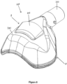
- FIG. 8 to 12 A further alternative form of a mask (not according to the present invention) is illustrated in Figures 8 to 12 .
- the mask 200 is similar to that described above and has a hollow body 201 and a cushion (not shown).
- the mask 200 is preferably a full face mask but may be a nasal mask or oronasal mask.
- the mask 200 has a gases inlet 202 that is capable of being connected to a conduit (such as inspiratory conduit 3, in Figure 1 ) that supplies gases to the mask from a humidifier and blower as described earlier.
- a conduit such as inspiratory conduit 3, in Figure 1
- an outlet vent and/or diffuser 203 is provided on the outside of the mask hollow body 201.
- the outlet vent and/or diffuser 203 has an outlet member or cover 205 that extends over a slot or plurality of holes in the mask body 201.
- This mask 200 has an alternative diffuser system where a narrow air gap 208 is formed between the outlet member 205 and the body 201, such that gases exhaled by the patient are forced through the air gap and diffused as they move out into the ambient air.
- a slot 204 (or series of holes, or any other means of allowing exhaled gases to exit the hollow body 201) are formed in the hollow body 201 and the outlet member 205, in the form of a cover is fitted about the slit 204.
- the cover 205 is substantially trapezoidal in shape and its bottom and side edges are fixed to the hollow body 201 of the mask 200. The bottom edge is substantially shorter in length than its top edges such that the width of the cover 203 increases from it's bottom to top edges.
- the cover 205 may be permanently fixed to the mask body (for example, by being welded, clipped or glued to the mask body 201) or may be able to be removed (for example, if the cover 205 was removably clipped to the mask body 201).
- the front face of the cover 205 extends outwards from the mask body 201 such that an angle ⁇ (see Figure 10 ) is formed between the mask body 201 and the front fact 205.
- This angle ⁇ is relatively low so that the gases exhaled by the patient that exit the gap 204 attach to the walls, in particular, the mask body wall 206 and the inner cover wall 207.
- the velocity of the gases passing through the air gap 208 reduces because the cross-sectional area of the gases flow increases as it moves out of the outlet member 203.
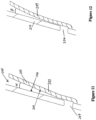
- the cover 205 may extend outwards from the mask body at a constant angle ⁇ , such as that shown in Figure 11 , so that the cover is substantially straight.
- ⁇ such as that shown in Figure 11
- the cover could be curved, so that the angle ⁇ between the mask body 210 and cover 209 gradually increases. It must be noted that the angle ⁇ will not exceed a predetermined angle, for example, it has been determined that angles greater than 20 degrees provide less than ideal diffusing of the exhales gases.
Description
- This invention relates to the delivery of respiratory gases, and in particular to patient interfaces for providing gases to patients requiring respiratory therapy.
- In the art of respiration devices, there are well known a variety of respiratory masks which cover the nose and/or mouth of a human user in order to provide a continuous seal around the nasal and/or oral areas of the face such that gas may be provided at positive pressure within the mask for consumption by the user. The uses for such masks range from high altitude breathing (i.e., aviation applications) to mining and fire fighting applications, to various medical diagnostic and therapeutic applications.
- One requisite of such respiratory devices has been that they provide an effective seal against the user's face to prevent leakage of the gas being supplied. Commonly, in prior mask configurations, a good mask-to-face seal has been attained in many instances only with considerable discomfort for the user. This problem is most crucial in those applications, especially medical applications, which require the user to wear such a mask continuously for hours or perhaps even days. In such situations, the user will not tolerate the mask for long durations and optimum therapeutic or diagnostic objectives thus will not be achieved, or will be achieved with great difficulty and considerable user discomfort.
- Where such masks as those used above are used in respiratory therapy, in particular treatment of obstructive sleep apnea (OSA) using Continuous Positive Airway Pressure (CPAP) therapy, there is generally provided in the art a vent for washout of the bias flow or expired gases to the atmosphere. Such a vent may be provided for example, as part of the mask, or in the case of some respirators where a further conduit carries the expiratory gases, at the respirator. The washout of gas from the mask is essential to ensure that carbon dioxide build up does not occur over the range of flow rates. In the typical flow rates in CPAP treatment, usually between 4cm H2O to 20cm H2O, prior art attempts at such vents have resulted in excessive noise causing irritation to the user and concentrated flows of gases irritating any bed partners.
- Various approaches have been developed in the prior art to attempt to reduce the noise by using slots to disperse the escaping gases when CPAP therapy is provided. For example,
US Patent Number 6460539 andUS Patent Number 3890966 . However, these prior art methods are not entirely satisfactory in eliminating the extra noise created by a vent at the mask. - International Publication No.
WO 00/78381 A1 -
United States Patent No. 6,584,977 B1 discloses a combined patient interface and integrated exhaust assembly that passes a controlled flow of gas from an interior of a patient interface to ambient atmosphere at a predetermined flow rate irrespective of variations of pressure in the interior of the patient interface device relative to ambient atmosphere. -
United States Patent No. 4,811,730 discloses a resuscitation mask which has a base member with an inflatable bladder about its periphery which seals against the face of the patient upon initial flow of air into the mask from the rescuer. A one-way valve and filter precludes flow of air and bodily fluids from the patient to the mouthpiece, and diverts exhaled air to the atmosphere about the mask. - European Patent Application Publication No.
EP 1 163 923 A2 discloses a patient interface with an outlet vent including a main vent which is diffused and muffled and a higher resistance vent provided in case the main vent is blocked. - International Publication No.
WO 02/051486 A1 - International Publication No.
WO 01/62326 A1 - It is an object of the present invention to attempt to provide a mask which goes some way to overcoming the abovementioned disadvantages in the prior art or which will at least provide the industry with a useful choice.
- The present invention provides a device for delivering a supply of gases to a user as defined in claim 1. Preferred embodiments of the present invention are defined in the dependent claims.
- The preferred form of the present invention will now be described with reference to the accompanying drawings.
-
Figure 1 is a block diagram of a humidified continuous positive airway pressure (CPAP system) as might be used in conjunction with the mask of the present invention. -
Figure 2 is a perspective exploded view of the mask and outlet member of the preferred embodiment of the mask of the present invention. -
Figure 3 is a perspective view of the mask of the present invention. -
Figure 4 is a side cross section of the mask and outlet member of the present invention. -
Figure 5 is a close up view of detail A ofFigure 4 of the mask of the present invention. -
Figure 6 is a perspective view of a first alternative form of a mask (not according to the present invention). -
Figure 7 is an exploded perspective view of the mask ofFigure 6 . -
Figure 8 is a perspective view of a second alternative form of a mask (not according to the present invention). -
Figure 9 is a side view of the mask ofFigure 8 . -
Figure 10 is a cross-section through BB of the mask onFigure 8 . -
Figure 11 is a close-up cross-section of a first form of the outlet member of the mask ofFigure 8 , where the outlet member curves away from the mask body. -
Figure 12 is a close-up cross-section of a second form of the outlet member for use with the mask ofFigure 8 , where the outlet member extends straight out from the mask body. -
Figure 13 is a side view of the mask ofFigure 2 , where the mask is shown to have a cushion that rests in use against and users face. - The present invention provides improvements in the field of CPAP therapy. In particular to a mask with a gas outlet is described which is quieter and has a more diffused outlet flow. In addition the manufacture of the gas outlet on a mask is simpler; it does not suffer to the same extent from excessive manufacturing faults. It will be appreciated that the mask as described in the preferred embodiment of the present invention can be used in respiratory care generally or with a ventilator but will now be described below with reference to use in a humidified CPAP system. It will also be appreciated that the outlet vent described is equally applicable to all forms of patent interface. It will also be appreciated that the outlet vent described can be used with various forms of mask, it is not limited to use with full face masks, but is described below with reference to full face masks.
- The full face mask of the present invention also has the added benefit of extending under the chin of the patient in use, and as such patients do not require a chin strap, as is the case with some prior art masks.
- With reference to
Figure 1 a humidified Continuous Positive Airway Pressure (CPAP) system is shown in which a patient 1 is receiving humidified and pressurised gases through a patient interface, for example a full face mask 2 (as shown inFigure 2 ) or other appropriate types of patient interfaces, such as nasal masks. Thepatient interface 2 is connected to a humidified gases transportation pathway orinspiratory conduit 3. It should be understood that delivery systems could also be VPAP (Variable Positive Airway Pressure) and BiPAP (Bi-level Positive Airway Pressure) or numerous other forms of respiratory therapy.Inspiratory conduit 3 is connected to the outlet 4 of ahumidification chamber 5 which contains a volume ofwater 6.Inspiratory conduit 3 may contain heating means or heater wires (not shown) which heat the walls of the conduit to reduce condensation of humidified gases within the conduit.Humidification chamber 6 is preferably formed from a plastics material and may have a highly heat conductive base (for example an aluminium base) which is in direct contact with aheater plate 7 ofhumidifier 8.Humidifier 8 is provided with control means orelectronic controller 9 which may comprise a microprocessor based controller executing computer software commands stored in associated memory. -
Controller 9 receives input from sources such as user input means ordial 10 through which a user of the device may, for example, set a predetermined required value (preset value) of humidity or temperature of the gases supplied to patient 1. The controller may also receive input from other sources, for example temperature and/orflow velocity sensors connector 13 and heaterplate temperature sensor 14. In response to the user set humidity or temperature value input viadial 10 and the other inputs,controller 9 determines when (or to what level) to energiseheater plate 7 to heat thewater 6 withinhumidification chamber 5. As the volume ofwater 6 withinhumidification chamber 5 is heated, water vapour begins to fill the volume of the chamber above the water's surface and is passed out of thehumidification chamber 5 outlet 4 with the flow of gases (for example air) provided from a gases supply means orblower 15 which enters the chamber throughinlet 16. Exhaled gases from the patient's mouth exit through vents in the mask and are passed to ambient surroundings, as shown inFigure 1 . -
Blower 15 is provided with variable pressure regulating means orvariable speed fan 21 which draws air or other gases throughblower inlet 17. The speed ofvariable speed fan 21 is controlled by electronic controller 18 (or alternatively the function ofcontroller 18 could carried out by controller 9) in response to inputs fromcontroller 9 and a user set predetermined required value (preset value) of pressure or fan speed viadial 19. - Referring to
Figure 2 and13 a patient interface that is a full face mask is shown in detail. Themask 2 includes ahollow body 30 andmask cushion 33. Themask cushion 33 resides within thehollow body 30 and provides cushioning of themask 2 or the patient's face. The hollow body and mask cushion are shown inFigures 1 and13 as extending under the patients chin, in particular, in the area indicated as 55. The extension under the chin of thecushion 33 provides a good seal and renders unnecessary a chin strap. - The
hollow body 30 has an integrally formedrecess 31. Therecess 31 preferably extends longitudinally along and over the width of themask body 30 but may not extend the full width of the mask as shown inFigure 2 . Further therecess 31 may not be a longitudinal recess but lateral or other orientation. An outlet member or insert 32 is fittable about or in the recess. Theinsert 32 substantially covers the whole of therecess 31. Therecess 31 and insert 32 each have complementarycircular apertures inspiratory inlet 36 when theinsert 32 is placed in therecess 30. Theinlet 36 is capable of being connected to the tubing that forms the inspiratory conduit 3 (as shown onFigure 1 ). Gases, supplied to theinspiratory conduit 3 from the CPAP device and humidifier, enter the mask through theapertures mask 2 is positioned around the nose and mouth of the user 1 and headgear (not shown) may be secured around the back of the head of the patient 1 to assist in the maintaining of the mask on the patient's face. The restraining force from the headgear on thehollow body 30 ensures enough compressive force on themask cushion 33 to provide an effective seal against the patient's face. - The
hollow body 30 and insert 32 are injection moulded in a relatively inflexible material, for example, polycarbonate plastic. Such a material would provide the requisite rigidity for the mask as well as being transparent and a relatively good insulator. - Referring to
Figure 3 , when theinsert 32 is in placed on the mask shell orhollow body 30 in therecess 31narrow slots 37, 38 are created between themask shell 30 andinsert 32. Theseslots 37, 38 act as expiratory vents for gases expired in use into the mask by the patient wearing the mask. - In some forms of the mask of the present invention the
insert 32 is removable, but in other forms the insert is welded in place to prevent removal. - The
insert 32 and narrow slots or outlet vents 37, 38 will now be described in more detail. Referring toFigures 2 to 5 , theinsert 32 is curved to follow the contours of themask shell 30 and has upper andlower sides right sides elongated recesses lower sides recesses insert 32 near to theinspiratory aperture 34 and do not extend over the full length of the upper andlower sides insert 32 attached or connected to the mask shell into therecess 31, formed at the boundary between theinsert 32 andmask shell 30 are narrow outlet vents 37, 38. - To provide support to the
insert 32, within the recess a number of walls are provided that the insert rests against. In particular, as shown inFigure 2 , a lowerinternal wall 48 havingside walls recess 31. The lower outlet vent 37 is actually formed between the boundary of thelower wall 48 and the lower side of theinsert 32. Upper internalsideways walls recess 31. These provide further support and each of theside walls slots 53, 54 of the four slots is shown inFigure 2 ). - The
insert 32 may be permanently fixed in themask shell 30 by gluing, ultrasonic welding or other appropriate fastening methods. In other forms, and particularly that shown inFigure 2 , theinsert 32 is removable from themask shell 30 and is provided withclips clips side aperture 47 is shown inFigure 2 ) at the sides of themask body 30. The clips merely need to be pushed inwards by a user to disengage them from theapertures 47 so that theinsert 32 can be removed. -
Figures 3 to 5 show the mask of the present invention in an in use form where theinsert 32 is attached to themask shell 30 and aconduit 3 that is inserted and held within theinspiratory inlet 36 and aperture formed in theinsert 32 and through themask shell 30. Theconduit 3 may be connected to anelbow connector 56, which may also be capable of swivelling within the aperture. - To ensure a proper seal around the outlet vents 37, 38 and between the
insert 32 and mask shell 30 a plastics gasket, for example, one made of elastomer, such as silicon, may be provided between theinsert 32 andmask shell 30. The gasket (not shown) would ensure sealing between these parts and reduce the noise of gases exiting thevents 37, 38. - It will be appreciated that by providing expiratory vents in the mask of the present invention effectively allows for minimising of the noise generated by the outward flow of expiratory gases form the mask, as well as reducing the noise level, the flow through the outlet vents is more diffused.
- An alternative form of a mask (not according to the present invention) is shown in
Figures 6 and 7 . Themask 100 has acushion 101, body orshell 102 and agases inlet 104 that receives gases from a conduit (forexample conduit 3 as described with reference toFigure 1 ). Themask shell 102 has a plurality of small diameter holes 105 in it that are ideally all directed away from the centre of the mask, i.e. diffusing or dispersing the flow of air. Theholes 105 are shown inFigures 6 and 7 as being circular but in other forms of the mask they may be otherwise shaped. Furthermore, the holes may be straight through the mask or have an alternative section, for example they may be narrow nearer the inner side of the mask and broader in section nearer the outer side of the mask shell 103. In order to be able to mould smallenough holes 105 in themask shell 102, the mask shell is preferably split into two or more sections (for example, the threesections Figure 7 ) although more or less sections could be provided in some forms of the mask. Thesections - This form of the mask would have the advantage that the plurality of
holes 105 produces less noise but there is difficulty in moulding thesections - A further alternative form of a mask (not according to the present invention) is illustrated in
Figures 8 to 12 . Themask 200 is similar to that described above and has ahollow body 201 and a cushion (not shown). Themask 200 is preferably a full face mask but may be a nasal mask or oronasal mask. Themask 200 has agases inlet 202 that is capable of being connected to a conduit (such asinspiratory conduit 3, inFigure 1 ) that supplies gases to the mask from a humidifier and blower as described earlier. In use when a patient is wearing themask 201 they breathe in the gases entering the mask through theinlet 202 and exhale into the mask. To vent exhaled gases an outlet vent and/ordiffuser 203 is provided on the outside of the maskhollow body 201. The outlet vent and/ordiffuser 203 has an outlet member or cover 205 that extends over a slot or plurality of holes in themask body 201. - This
mask 200 has an alternative diffuser system where anarrow air gap 208 is formed between theoutlet member 205 and thebody 201, such that gases exhaled by the patient are forced through the air gap and diffused as they move out into the ambient air. In particular, a slot 204 (or series of holes, or any other means of allowing exhaled gases to exit the hollow body 201) are formed in thehollow body 201 and theoutlet member 205, in the form of a cover is fitted about theslit 204. Thecover 205 is substantially trapezoidal in shape and its bottom and side edges are fixed to thehollow body 201 of themask 200. The bottom edge is substantially shorter in length than its top edges such that the width of thecover 203 increases from it's bottom to top edges. Thecover 205 may be permanently fixed to the mask body (for example, by being welded, clipped or glued to the mask body 201) or may be able to be removed (for example, if thecover 205 was removably clipped to the mask body 201). - Referring to
Figures 9 and 10 , the front face of thecover 205 extends outwards from themask body 201 such that an angle α (seeFigure 10 ) is formed between themask body 201 and thefront fact 205. This angle α is relatively low so that the gases exhaled by the patient that exit thegap 204 attach to the walls, in particular, themask body wall 206 and theinner cover wall 207. With the gradual expansion in the area inside of thecover 205 the velocity of the gases passing through theair gap 208 reduces because the cross-sectional area of the gases flow increases as it moves out of theoutlet member 203. - Referring now to
Figures 11 and 12 , in the preferred form of the mask, thecover 205 may extend outwards from the mask body at a constant angle α, such as that shown inFigure 11 , so that the cover is substantially straight. In other forms of the cover (such as thatcover 209 shown inFigure 12 ) could be curved, so that the angle β between themask body 210 and cover 209 gradually increases. It must be noted that the angle β will not exceed a predetermined angle, for example, it has been determined that angles greater than 20 degrees provide less than ideal diffusing of the exhales gases.
Claims (13)
- A device for delivering a supply of gases to a user (1), comprising:a patient interface (2), in use in fluid communication with said supply of gases and supplying said gases to said user (1), the patient interface (2) comprising a hollow body (30) and a mask cushion (33), wherein the mask cushion (33) resides within the hollow body (30) and provides cushioning of the patient interface (2) on the user's (1) face, and the hollow body (30) has an integrally formed recess (31),characterized in that:
an outlet member (32) is placed in the recess (31) and integrated with or attached to said hollow body (30), wherein the outlet member (32) is curved to follow the contours of the hollow body (30) and has upper and lower sides (39, 40) that taper down towards left and right sides (41, 42) of the outlet member (32), and the boundary between said outlet member (32) and said hollow body (30) forms at least one narrow outlet vent (37, 38) that in use passes a substantial portion of the expired gases of said user (1). - The device of claim 1, wherein the recess (31) and the outlet member (32) each have complementary circular apertures (34, 35) that form an inspiratory inlet (36) when the outlet member (32) is placed in the recess (31).
- The device of claim 1 or claim 2, wherein two elongated recesses (43, 44) are formed on the upper and lower sides (39, 40) of the outlet member (32), the two elongated recesses (43, 44) forming two narrow outlet vents (37, 38) at the boundary between said outlet member (32) and said hollow body (30).
- The device of claim 2, wherein two elongated recesses (43, 44) are formed on the upper and lower sides (39, 40) of the outlet member (32), the two elongated recesses (43, 44) forming two narrow outlet vents (37, 38) at the boundary between said outlet member (32) and said hollow body (30), and wherein the elongated recesses (43, 44) are formed in a middle section of the outlet member (32) near to the aperture (34) of the outlet member (32), and do not extend over the full length of the upper and lower sides (39, 40) of the outlet member (32).
- The device of claim 3, wherein the elongated recesses (43, 44) extend along the full length of the upper and lower sides (39, 40) of the outlet member (32).
- The device of claim any one of the preceding claims, wherein within the recess (31) a number of walls (49, 50, 52, 53) are provided that the outlet member (32) rests against.
- The device of claim 6, wherein the number of walls (49, 50, 52, 53) comprises side walls (49, 50) extending upwards from a lower internal wall (48) formed at a lower edge of the recess (31), and upper internal sideways walls (52, 53) formed in the recess (31).
- The device of any one of the preceding claims, wherein said at least one outlet vent (37, 38) extends between the top and bottom of said patient interface (2).
- The device of any one of the preceding claims, wherein said patient interface (2) is a nasal mask.
- The device of any one of the preceding claims, wherein the recess (31) extends longitudinally along and over the width of the hollow body (30).
- The device of any one of the preceding claims, wherein the hollow body (30) and outlet member (32) are injection moulded in a relatively inflexible material, for example polycarbonate plastic.
- The device of any one of the preceding claims, wherein the outlet member (32) is removable.
- The device of any one of claims 1 to 11, wherein the outlet member (32) is permanently fixed in the hollow body (30) by gluing, ultrasonic welding or other appropriate fastening methods.
Applications Claiming Priority (4)
| Application Number | Priority Date | Filing Date | Title |
|---|---|---|---|
| NZ52802903 | 2003-09-03 | ||
| EP19195201.9A EP3626293B1 (en) | 2003-09-03 | 2004-08-20 | Device for supplying breathing gas to a patient |
| PCT/NZ2004/000194 WO2005021075A1 (en) | 2003-09-03 | 2004-08-20 | A mask |
| EP04775120.1A EP1663366B1 (en) | 2003-09-03 | 2004-08-20 | A mask |
Related Parent Applications (3)
| Application Number | Title | Priority Date | Filing Date |
|---|---|---|---|
| EP19195201.9A Division EP3626293B1 (en) | 2003-09-03 | 2004-08-20 | Device for supplying breathing gas to a patient |
| EP19195201.9A Division-Into EP3626293B1 (en) | 2003-09-03 | 2004-08-20 | Device for supplying breathing gas to a patient |
| EP04775120.1A Division EP1663366B1 (en) | 2003-09-03 | 2004-08-20 | A mask |
Publications (2)
| Publication Number | Publication Date |
|---|---|
| EP3838323A1 EP3838323A1 (en) | 2021-06-23 |
| EP3838323B1 true EP3838323B1 (en) | 2023-04-05 |
Family
ID=34270858
Family Applications (3)
| Application Number | Title | Priority Date | Filing Date |
|---|---|---|---|
| EP04775120.1A Active EP1663366B1 (en) | 2003-09-03 | 2004-08-20 | A mask |
| EP19195201.9A Active EP3626293B1 (en) | 2003-09-03 | 2004-08-20 | Device for supplying breathing gas to a patient |
| EP21156388.7A Active EP3838323B1 (en) | 2003-09-03 | 2004-08-20 | Respiratory mask with gas washout vent |
Family Applications Before (2)
| Application Number | Title | Priority Date | Filing Date |
|---|---|---|---|
| EP04775120.1A Active EP1663366B1 (en) | 2003-09-03 | 2004-08-20 | A mask |
| EP19195201.9A Active EP3626293B1 (en) | 2003-09-03 | 2004-08-20 | Device for supplying breathing gas to a patient |
Country Status (4)
| Country | Link |
|---|---|
| US (9) | US8714157B2 (en) |
| EP (3) | EP1663366B1 (en) |
| AU (1) | AU2004268479B2 (en) |
| WO (1) | WO2005021075A1 (en) |
Families Citing this family (95)
| Publication number | Priority date | Publication date | Assignee | Title |
|---|---|---|---|---|
| WO2004052438A1 (en) | 2002-12-06 | 2004-06-24 | Fisher & Paykel Healthcare Limited | Mouthpiece |
| US7874293B2 (en) | 2003-02-21 | 2011-01-25 | Resmed Limited | Nasal assembly |
| EP1663366B1 (en) | 2003-09-03 | 2019-11-13 | Fisher & Paykel Healthcare Limited | A mask |
| CN101628142B (en) | 2003-12-31 | 2014-03-26 | 雷斯梅德有限公司 | Compact oronasal patient interface |
| US8783257B2 (en) | 2004-02-23 | 2014-07-22 | Fisher & Paykel Healthcare Limited | Breathing assistance apparatus |
| WO2005094928A1 (en) | 2004-04-02 | 2005-10-13 | Fisher & Paykel Healthcare Limited | Breathing assistance apparatus |
| US9072852B2 (en) | 2004-04-02 | 2015-07-07 | Fisher & Paykel Healthcare Limited | Breathing assistance apparatus |
| EP1740247B1 (en) | 2004-04-15 | 2012-09-26 | ResMed Limited | Positive-air-pressure machine conduit |
| DE102005041717B4 (en) | 2004-09-03 | 2021-11-04 | Löwenstein Medical Technology S.A. | Breathing mask with flow guide structures |
| EP2388037B8 (en) * | 2004-09-03 | 2016-09-21 | Löwenstein Medical Technology GmbH + Co. KG | Respiratory mask |
| US7237551B2 (en) | 2004-12-22 | 2007-07-03 | Ric Investments, Llc. | Cushion for a patient interface |
| EP2712644A1 (en) | 2005-01-12 | 2014-04-02 | ResMed Limited | Cushion for patient interface |
| CN107320833B (en) | 2005-06-06 | 2022-06-03 | 瑞思迈私人有限公司 | Mask system |
| US7455063B2 (en) | 2005-06-17 | 2008-11-25 | Nellcor Puritan Bennett Llc | Adjustable gas delivery mask having a flexible gasket |
| US7827987B2 (en) | 2005-06-17 | 2010-11-09 | Nellcor Puritan Bennett Llc | Ball joint for providing flexibility to a gas delivery pathway |
| US7900630B2 (en) | 2005-06-17 | 2011-03-08 | Nellcor Puritan Bennett Llc | Gas delivery mask with flexible bellows |
| US7849855B2 (en) * | 2005-06-17 | 2010-12-14 | Nellcor Puritan Bennett Llc | Gas exhaust system for a gas delivery mask |
| NZ565507A (en) | 2005-10-14 | 2011-06-30 | Resmed Ltd | Mask with cushion having lip which in use deflects against frame of mask |
| NZ612787A (en) | 2005-10-25 | 2015-01-30 | Resmed Ltd | Interchangeable mask assembly |
| US20090151729A1 (en) | 2005-11-08 | 2009-06-18 | Resmed Limited | Nasal Assembly |
| ES2900194T3 (en) | 2006-07-14 | 2022-03-16 | Fisher & Paykel Healthcare Ltd | respiratory assistance device |
| US9162034B2 (en) | 2006-07-28 | 2015-10-20 | Resmed Limited | Delivery of respiratory therapy |
| EP2428241B1 (en) | 2006-07-28 | 2016-07-06 | ResMed Limited | Delivery of respiratory therapy |
| USD635661S1 (en) | 2006-11-14 | 2011-04-05 | Resmed Limited | Frame for respiratory mask |
| WO2008058330A1 (en) * | 2006-11-14 | 2008-05-22 | Resmed Ltd | Frame and vent assembly for mask assembly |
| EP2481434B1 (en) | 2006-12-15 | 2016-04-13 | ResMed Ltd. | Delivery of respiratory therapy |
| US8517023B2 (en) | 2007-01-30 | 2013-08-27 | Resmed Limited | Mask system with interchangeable headgear connectors |
| NZ589685A (en) | 2007-04-19 | 2012-06-29 | Resmed Ltd | Cushion for patient breathing interface with variable density foam supported membrane |
| US8397727B2 (en) | 2007-08-24 | 2013-03-19 | Resmed Limited | Mask vent |
| AU2008319519A1 (en) * | 2007-10-30 | 2009-05-07 | Fisher & Paykel Healthcare Limited | Fan unit with bypass vent holes |
| US11331447B2 (en) | 2008-03-04 | 2022-05-17 | ResMed Pty Ltd | Mask system with snap-fit shroud |
| AU2009221630B2 (en) | 2008-03-04 | 2014-07-17 | ResMed Pty Ltd | Mask system |
| CA2724531A1 (en) * | 2008-04-14 | 2009-10-22 | Deka Products Limited Partnership | Devices, systems, and methods for aiding in the detection of a physiological abnormality |
| US10258757B2 (en) | 2008-05-12 | 2019-04-16 | Fisher & Paykel Healthcare Limited | Patient interface and aspects thereof |
| US10792451B2 (en) | 2008-05-12 | 2020-10-06 | Fisher & Paykel Healthcare Limited | Patient interface and aspects thereof |
| NZ618492A (en) | 2008-06-05 | 2015-09-25 | Resmed Ltd | Treatment of respiratory conditions |
| US11660413B2 (en) | 2008-07-18 | 2023-05-30 | Fisher & Paykel Healthcare Limited | Breathing assistance apparatus |
| WO2010041966A1 (en) | 2008-10-10 | 2010-04-15 | Fisher & Paykel Healthcare Limited | Nasal pillows for a patient interface |
| CN103656823B (en) | 2008-11-27 | 2016-09-07 | 帝人制药株式会社 | Breathing mask wear part and breathing mask |
| WO2010067237A2 (en) * | 2008-12-11 | 2010-06-17 | Koninklijke Philips Electronics, N.V. | Exhaust vent configuration |
| US9095673B2 (en) | 2008-12-15 | 2015-08-04 | Resmed Limited | Unobtrusive nasal mask |
| US20100282264A1 (en) * | 2009-05-05 | 2010-11-11 | Hsiner Company, Ltd. | Respiratory mask having a damping ring |
| WO2011022751A1 (en) | 2009-08-26 | 2011-03-03 | Resmed Ltd | Mask system |
| EP3741418A1 (en) | 2009-11-18 | 2020-11-25 | Fisher & Paykel Healthcare Limited | Nasal interface |
| GB2527432B (en) | 2009-12-23 | 2016-04-06 | Fisher & Paykel Healthcare Ltd | Patient interface and headgear |
| CN102711890A (en) * | 2009-12-28 | 2012-10-03 | 皇家飞利浦电子股份有限公司 | Exhaust port assembly that minimizes noise |
| NZ701074A (en) | 2010-09-30 | 2015-10-30 | Resmed Ltd | Mask system |
| NZ607679A (en) | 2010-09-30 | 2014-07-25 | Resmed Ltd | Patient interface systems |
| EP3406287B1 (en) | 2010-10-08 | 2022-04-27 | Fisher & Paykel Healthcare Limited | Respiratory mask assembly for breathing assistance apparatus |
| US9339623B2 (en) | 2010-10-22 | 2016-05-17 | Koninklijke Philips N.V. | Exhaust gas assembly for a patient interface device |
| US10603456B2 (en) | 2011-04-15 | 2020-03-31 | Fisher & Paykel Healthcare Limited | Interface comprising a nasal sealing portion |
| GB2532393B (en) | 2011-04-15 | 2016-07-06 | Fisher & Paykel Healthcare Ltd | Interface comprising a rolling nasal bridge portion |
| CA2870429C (en) * | 2012-04-16 | 2017-05-16 | Metran Co., Ltd. | Opening and closing device and respiratory assistance device |
| GB2553475B8 (en) | 2012-08-08 | 2019-01-02 | Fisher & Paykel Healthcare Ltd | Headgear for patient interface |
| EP4279106A3 (en) | 2012-09-04 | 2024-01-17 | Fisher & Paykel Healthcare Limited | Valsalva mask |
| CN108114356B (en) | 2012-11-16 | 2021-06-22 | 费雪派克医疗保健有限公司 | Nasal seal for mask interface |
| WO2014129913A1 (en) * | 2013-02-21 | 2014-08-28 | Fisher & Paykel Healthcare Limited | Patient interface with venting |
| WO2015088362A1 (en) | 2013-12-11 | 2015-06-18 | Fisher & Paykel Healthcare Limited | Respiratory interface |
| CA3169186A1 (en) | 2014-06-04 | 2015-12-10 | Revolutionary Medical Devices, Inc. | Combined nasal and mouth ventilation mask |
| AU2015305893B2 (en) | 2014-08-20 | 2020-05-28 | Sunmed Group Holdings, Llc | Ventilation mask |
| GB2591416B (en) | 2014-08-25 | 2022-01-05 | Fisher & Paykel Healthcare Ltd | Respiratory mask and related portions, components or sub-assemblies |
| TWI708572B (en) | 2014-09-16 | 2020-11-01 | 紐西蘭商費雪&佩凱爾關心健康有限公司 | Intramold headgear |
| CN111437485B (en) | 2014-09-18 | 2023-09-05 | 瑞思迈私人有限公司 | Gas washout vent for patient interface |
| US10646680B2 (en) | 2014-09-19 | 2020-05-12 | Fisher & Paykel Healthcare Limited | Headgear assemblies and interface assemblies with headgear |
| USD825740S1 (en) | 2014-12-12 | 2018-08-14 | Revolutionary Medical Devices | Surgical mask |
| US10010313B2 (en) | 2015-05-18 | 2018-07-03 | Richard L. Arden | Mandibular subluxation device and method |
| US10258319B2 (en) | 2015-05-18 | 2019-04-16 | Richard L. Arden | Airway assist device and method |
| EP3307367B1 (en) | 2015-06-11 | 2021-08-04 | Revolutionary Medical Devices, Inc. | Ventilation mask |
| US10342526B2 (en) | 2015-07-01 | 2019-07-09 | Richard L. Arden | Airway assist device and method |
| CN109152904B (en) * | 2016-03-15 | 2021-05-28 | 费雪派克医疗保健有限公司 | Respiratory mask system |
| SG10202009038XA (en) | 2016-03-16 | 2020-10-29 | Fisher & Paykel Healthcare Ltd | Strap assembly, strap connector, headgear, headgear assembly, method of forming headgear, tubular connector, patient interface and method of joining straps |
| AU2017234346B2 (en) | 2016-03-16 | 2022-06-30 | Fisher & Paykel Healthcare Limited | Directional lock for interface headgear arrangement |
| SG11201807697QA (en) | 2016-03-16 | 2018-10-30 | Fisher & Paykel Healthcare Ltd | Intra-mould substrate |
| USD882066S1 (en) | 2016-05-13 | 2020-04-21 | Fisher & Paykel Healthcare Limited | Frame for a breathing mask |
| CN114569858A (en) | 2016-09-14 | 2022-06-03 | 革新医疗器械有限公司 | Ventilation mask |
| US9629975B1 (en) | 2016-09-14 | 2017-04-25 | Revolutionary Medical Devices, Inc. | Ventilation mask |
| USD848606S1 (en) | 2016-11-07 | 2019-05-14 | Revolutionary Medical Devices, Inc. | Surgical mask |
| EP4316560A3 (en) | 2016-11-11 | 2024-04-03 | ResMed Pty Ltd | Gas washout vent for patient interface |
| USD817478S1 (en) | 2017-01-25 | 2018-05-08 | Fisher & Paykel Healthcare Limited | Exhalation port for breathing circuit |
| USD824020S1 (en) | 2017-02-23 | 2018-07-24 | Fisher & Paykel Healthcare Limited | Cushion assembly for breathing mask assembly |
| USD823455S1 (en) | 2017-02-23 | 2018-07-17 | Fisher & Paykel Healthcare Limited | Cushion assembly for breathing mask assembly |
| USD823454S1 (en) | 2017-02-23 | 2018-07-17 | Fisher & Paykel Healthcare Limited | Cushion assembly for breathing mask assembly |
| USD874646S1 (en) | 2017-03-09 | 2020-02-04 | Fisher & Paykel Healthcare Limited | Headgear component for a nasal mask assembly |
| USD901673S1 (en) | 2017-03-09 | 2020-11-10 | Fisher & Paykel Healthcare Limited | Frame and breathing tube assembly for a nasal mask |
| US20180361093A1 (en) * | 2017-06-19 | 2018-12-20 | Loewenstein Medical Technology S.A. | Breathing mask interface with small required operating force |
| USD875242S1 (en) | 2017-09-20 | 2020-02-11 | Fisher & Paykel Healthcare Limited | Nasal mask and breathing tube set |
| USD855793S1 (en) | 2017-09-20 | 2019-08-06 | Fisher & Paykel Healthcare Limited | Frame for a nasal mask |
| JP7145939B2 (en) | 2017-09-29 | 2022-10-03 | コーニンクレッカ フィリップス エヌ ヴェ | Customizable masks and how to adjust their size |
| USD898188S1 (en) | 2017-11-17 | 2020-10-06 | Revolutionary Medical Devices, Inc. | Surgical mask |
| WO2019175814A1 (en) | 2018-03-16 | 2019-09-19 | Fisher & Paykel Healthcare Limited | Headgear with lock disengagement mechanism |
| BR112021000496A2 (en) | 2018-07-31 | 2021-04-06 | Vyaire Medical, Inc. | VENTILATION MASK |
| US11745033B2 (en) | 2019-03-17 | 2023-09-05 | Brett Patrick | Process and apparatus to preclude unfiltered atmospheric gases and human respiration products including carbon-dioxide with carbon-14 from entering controlled greenhouse atmospheric gases |
| CA3140428A1 (en) | 2019-06-11 | 2020-12-17 | Heikki Haveri | Respiration sensor attachment device |
| USD923775S1 (en) | 2020-04-24 | 2021-06-29 | Inland Concrete Products, Inc. | Hygienic face mask |
| CN117355349A (en) * | 2021-03-31 | 2024-01-05 | 瑞思迈私人有限公司 | Ventilation arrangement for a patient interface |
Family Cites Families (88)
| Publication number | Priority date | Publication date | Assignee | Title |
|---|---|---|---|---|
| SU72692A1 (en) * | 1944-04-01 | 1947-11-30 | В.Г. Лейтес | Yeast Growing Method |
| US3890966A (en) | 1973-11-01 | 1975-06-24 | Johnson & Johnson | Anti-fog surgical face mask with slits |
| SE382388B (en) * | 1973-12-19 | 1976-02-02 | Gnosjoeplast Ab | BREATHING MASK, SPECIAL FOR ARTIFICIAL BREATHING |
| SU726692A1 (en) * | 1978-04-11 | 1981-09-07 | Кубанский Ордена Трудового Красного Знамени Сельскохозяйственный Институт | Protecting mask |
| US4258710A (en) * | 1978-08-16 | 1981-03-31 | Reber Fred L | Mask-type respirator |
| US4573463A (en) * | 1982-08-02 | 1986-03-04 | Hall Lester B | Breathing mask |
| US4706683A (en) * | 1985-12-20 | 1987-11-17 | Bowman Gray School Of Medicine, Wake Forest University | Method and apparatus for bolus delivery of gases and aerosols and insufflations |
| EP0266456A1 (en) * | 1986-11-06 | 1988-05-11 | Moldex-Metric AG & Co.KG | Respiratory face mask |
| US5062421A (en) | 1987-11-16 | 1991-11-05 | Minnesota Mining And Manufacturing Company | Respiratory mask having a soft, compliant facepiece and a thin, rigid insert and method of making |
| US4811730A (en) * | 1988-07-18 | 1989-03-14 | Seitz Corporation | CPR face mask and method of using same |
| US5243971A (en) * | 1990-05-21 | 1993-09-14 | The University Of Sydney | Nasal mask for CPAP having ballooning/moulding seal with wearer's nose and facial contours |
| US5662101A (en) | 1995-12-07 | 1997-09-02 | Respironics, Inc. | Respiratory facial mask |
| US5657752A (en) | 1996-03-28 | 1997-08-19 | Airways Associates | Nasal positive airway pressure mask and method |
| AUPO126596A0 (en) * | 1996-07-26 | 1996-08-22 | Resmed Limited | A nasal mask and mask cushion therefor |
| US5758642A (en) * | 1996-10-02 | 1998-06-02 | Choi; Myung Ja | Gas delivery mask |
| US6192886B1 (en) | 1996-10-17 | 2001-02-27 | Hans Rudolph, Inc. | Nasal mask |
| US5921239A (en) * | 1997-01-07 | 1999-07-13 | Sunrise Medical Hhg Inc. | Face mask for patient breathing |
| AUPP855099A0 (en) * | 1999-02-09 | 1999-03-04 | Resmed Limited | Gas delivery connection assembly |
| US6561191B1 (en) * | 1997-02-10 | 2003-05-13 | Resmed Limited | Mask and a vent assembly therefor |
| AUPO504597A0 (en) * | 1997-02-10 | 1997-03-06 | Resmed Limited | A mask and a vent assembly therefor |
| US5937851A (en) * | 1997-02-27 | 1999-08-17 | Respironics, Inc. | Swivel device utilizing bearing clearance to allow carbon dioxide laden exhaust |
| US6062221A (en) | 1997-10-03 | 2000-05-16 | 3M Innovative Properties Company | Drop-down face mask assembly |
| US6119693A (en) | 1998-01-16 | 2000-09-19 | Resmed Limited | Forehead support for facial mask |
| US6796308B2 (en) | 1998-12-09 | 2004-09-28 | Resmed Limited | Mask cushion and frame assembly |
| AUPQ102999A0 (en) * | 1999-06-18 | 1999-07-08 | Resmed Limited | A connector for a respiratory mask and a respiratory mask |
| US6338342B1 (en) | 1999-02-22 | 2002-01-15 | Cabot Safety Intermediate Corporation | Respirator headpiece and release mechanism |
| US6398197B1 (en) | 1999-05-10 | 2002-06-04 | Fisher & Paykel Limited | Water chamber |
| US6412488B1 (en) | 1999-05-12 | 2002-07-02 | Respironics, Inc. | Low contact nasal mask and system using same |
| JP2000325481A (en) * | 1999-05-25 | 2000-11-28 | Fujisawa Pharmaceut Co Ltd | Mask for respiration |
| US6631718B1 (en) | 1999-06-08 | 2003-10-14 | Sleepnet Corporation | Air mask with seal |
| US6467483B1 (en) * | 1999-07-28 | 2002-10-22 | Respironics, Inc. | Respiratory mask |
| US6435181B1 (en) * | 1999-08-30 | 2002-08-20 | Sunrise Medical Hhg Inc. | Respiratory mask with adjustable exhaust vent |
| EP1900388B1 (en) * | 2000-02-25 | 2013-06-05 | ResMed R&D Germany GmbH | Seal device for a respiratory mask |
| US7111624B2 (en) | 2000-03-21 | 2006-09-26 | Fisher & Paykel Healthcare Limited | Apparatus for delivering humidified gases |
| US6584977B1 (en) * | 2000-04-06 | 2003-07-01 | Respironics, Inc. | Combined patient interface and exhaust assembly |
| US6581594B1 (en) * | 2000-05-15 | 2003-06-24 | Resmed Limited | Respiratory mask having gas washout vent and gas washout vent for respiratory mask |
| ATE309835T1 (en) * | 2000-06-14 | 2005-12-15 | Fisher & Paykel Healthcare Ltd | NOSE MASK |
| US6986352B2 (en) | 2000-06-22 | 2006-01-17 | Resmed Limited | Mask with gusset |
| WO2002009642A2 (en) | 2000-07-28 | 2002-02-07 | University Of Maryland, Baltimore | Accessory cholera enterotoxin and analogs thereof as activators of calcium dependent chloride channel |
| US6530373B1 (en) | 2000-08-04 | 2003-03-11 | Mallinckrodt Inc. | Respirator mask |
| US20020020416A1 (en) | 2000-08-11 | 2002-02-21 | David Namey | Two-shot injection molded nasal/oral mask |
| US6679261B2 (en) | 2000-08-24 | 2004-01-20 | Resmed Limited | Forehead support for facial mask |
| US6460539B1 (en) | 2000-09-21 | 2002-10-08 | 3M Innovative Properties Company | Respirator that includes an integral filter element, an exhalation valve, and impactor element |
| DE20017940U1 (en) | 2000-10-19 | 2000-12-28 | Map Gmbh | Breathing mask for supplying a breathing gas to a mask user and a derivation device for deriving breathing gas |
| US6427694B1 (en) | 2000-11-22 | 2002-08-06 | Mpv-Truma Gesellschaft Fur Medizintechnische Produkte Gmbh | Nasal breathing mask |
| DE10057883C1 (en) | 2000-11-22 | 2002-08-01 | Mpv Truma Ges Fuer Medizintech | Nasal ventilation mask |
| AUPR193300A0 (en) | 2000-12-07 | 2001-01-04 | Resmed Limited | Mask assembly |
| DE20122945U1 (en) | 2000-12-12 | 2011-05-12 | ResMed Ltd., Bella Vista | headband |
| US8439035B2 (en) * | 2000-12-22 | 2013-05-14 | Resmed Limited | Flow regulation vent |
| RU2186597C1 (en) * | 2001-01-16 | 2002-08-10 | Закрытое акционерное общество "Сорбент-Центр Внедрение" | Semimask for respirator |
| US20020139368A1 (en) | 2001-03-29 | 2002-10-03 | Bachinski Thomas J. | Oxygen sensor mounting in medical or flight crew masks for direct indication of blood level oxygen |
| US6851425B2 (en) * | 2001-05-25 | 2005-02-08 | Respironics, Inc. | Exhaust port assembly for a pressure support system |
| DE10126808C1 (en) * | 2001-06-01 | 2002-08-14 | Pari Gmbh | inhalation mask |
| CA2456216C (en) | 2001-08-10 | 2008-07-22 | North Safety Products Inc. | Respirator |
| ATE473774T1 (en) | 2001-10-22 | 2010-07-15 | Map Medizin Technologie Gmbh | MEDICAL MASK |
| US8042542B2 (en) | 2002-04-23 | 2011-10-25 | Resmed Limited | Respiratory mask assembly with magnetic coupling to headgear assembly |
| AUPS192602A0 (en) | 2002-04-23 | 2002-05-30 | Resmed Limited | Nasal mask |
| CN100592926C (en) | 2002-09-06 | 2010-03-03 | 雷斯梅德有限公司 | Cushion for a respiratory mask assembly |
| US8490623B2 (en) | 2002-11-06 | 2013-07-23 | Resmed Limited | Mask and components thereof |
| EP2591818B1 (en) | 2002-11-08 | 2015-12-16 | ResMed Limited | Headgear assembly for a respiratory mask assembly |
| US6736139B1 (en) * | 2003-02-20 | 2004-05-18 | Mark Wix | Ventilation mask assist device |
| US7874293B2 (en) | 2003-02-21 | 2011-01-25 | Resmed Limited | Nasal assembly |
| US7621274B2 (en) | 2003-03-22 | 2009-11-24 | Invacare Corporation | Nasal mask |
| US7188622B2 (en) * | 2003-06-19 | 2007-03-13 | 3M Innovative Properties Company | Filtering face mask that has a resilient seal surface in its exhalation valve |
| US20050011524A1 (en) | 2003-07-17 | 2005-01-20 | Marguerite Thomlinson | Nasal interface apparatus |
| EP1663366B1 (en) | 2003-09-03 | 2019-11-13 | Fisher & Paykel Healthcare Limited | A mask |
| AU2004292336B2 (en) | 2003-11-25 | 2011-07-07 | ResMed Pty Ltd | Vent system for CPAP patient interface used in treatment of sleep disordered breathing |
| US7178525B2 (en) | 2004-02-06 | 2007-02-20 | Ric Investments, Llc | Patient interface assembly supported under the mandible |
| NZ551715A (en) | 2004-06-16 | 2011-02-25 | Resmed Ltd | Single piece, gussetted cushion for a respiratory mask assembly |
| DE202005021927U1 (en) | 2004-06-25 | 2011-06-09 | ResMed Ltd., New South Wales | Forehead support for a patient interface |
| DK4049703T3 (en) | 2004-08-20 | 2023-12-18 | Fisher & Paykel Healthcare Ltd | APPARATUS FOR MEASURING PROPERTIES OF GASES SUPPLIED TO A PATIENT |
| US7353827B2 (en) | 2004-09-01 | 2008-04-08 | Vitol Signs, Inc. | Mask, mask shell and seal with improved mounting, mask seal, method of mask manufacture and mask with reduced exhalation noise |
| US7624735B2 (en) | 2004-09-21 | 2009-12-01 | Respironics Respiratory Drug Delivery (Uk) Ltd | Cheek-mounted patient interface |
| US8042539B2 (en) | 2004-12-10 | 2011-10-25 | Respcare, Inc. | Hybrid ventilation mask with nasal interface and method for configuring such a mask |
| NZ589953A (en) | 2005-01-12 | 2012-07-27 | Resmed Ltd | Respiratory mask with gusseted cushions |
| CN107320833B (en) | 2005-06-06 | 2022-06-03 | 瑞思迈私人有限公司 | Mask system |
| US8245711B2 (en) | 2005-08-15 | 2012-08-21 | Ric Investments, Llc | Patient interface with adjustable cushion |
| NZ565507A (en) | 2005-10-14 | 2011-06-30 | Resmed Ltd | Mask with cushion having lip which in use deflects against frame of mask |
| NZ567372A (en) | 2005-10-17 | 2011-06-30 | Resmed Ltd | Anti-asphyxia valve assembly for respiratory mask with clip member to secure AAV assemblywithin an elbow |
| NZ612787A (en) | 2005-10-25 | 2015-01-30 | Resmed Ltd | Interchangeable mask assembly |
| EP2020978A1 (en) | 2006-05-25 | 2009-02-11 | Respcare, Inc. | Hybrid ventilation mask with nasal interface and method for configuring such a mask |
| WO2008040050A1 (en) | 2006-10-02 | 2008-04-10 | Resmed Ltd | Cushion for mask system |
| US7500480B2 (en) | 2006-06-16 | 2009-03-10 | Koninklijke Philips Electronics N.V. | Chin pivot patient interface device |
| ES2900194T3 (en) | 2006-07-14 | 2022-03-16 | Fisher & Paykel Healthcare Ltd | respiratory assistance device |
| US8517023B2 (en) | 2007-01-30 | 2013-08-27 | Resmed Limited | Mask system with interchangeable headgear connectors |
| AU2009221630B2 (en) | 2008-03-04 | 2014-07-17 | ResMed Pty Ltd | Mask system |
| CN108744216A (en) | 2008-12-10 | 2018-11-06 | 瑞思迈有限公司 | Headband for mask |
| FR3038841A1 (en) | 2015-07-15 | 2017-01-20 | Akse | PROBE DEVICE FOR THE MANAGEMENT OF URINARY INCONTINENCE AT THE EFFORT |
-
2004
- 2004-08-20 EP EP04775120.1A patent/EP1663366B1/en active Active
- 2004-08-20 EP EP19195201.9A patent/EP3626293B1/en active Active
- 2004-08-20 WO PCT/NZ2004/000194 patent/WO2005021075A1/en active Application Filing
- 2004-08-20 EP EP21156388.7A patent/EP3838323B1/en active Active
- 2004-08-20 AU AU2004268479A patent/AU2004268479B2/en not_active Ceased
- 2004-08-20 US US10/570,226 patent/US8714157B2/en active Active
-
2014
- 2014-05-05 US US14/270,200 patent/US9144655B2/en active Active
-
2015
- 2015-08-21 US US14/832,271 patent/US9339621B2/en active Active
-
2016
- 2016-05-16 US US15/156,073 patent/US10004865B2/en active Active
-
2017
- 2017-10-20 US US15/789,268 patent/US10034994B2/en active Active
-
2018
- 2018-06-18 US US16/010,827 patent/US10765826B2/en active Active
-
2020
- 2020-05-11 US US16/871,683 patent/US10828448B2/en active Active
- 2020-10-01 US US17/061,407 patent/US11179532B2/en active Active
-
2021
- 2021-01-14 US US17/149,300 patent/US11607514B2/en active Active
Also Published As
| Publication number | Publication date |
|---|---|
| US9144655B2 (en) | 2015-09-29 |
| EP1663366A4 (en) | 2013-01-09 |
| EP3626293A1 (en) | 2020-03-25 |
| US9339621B2 (en) | 2016-05-17 |
| US20140318548A1 (en) | 2014-10-30 |
| AU2004268479A1 (en) | 2005-03-10 |
| US20160310687A1 (en) | 2016-10-27 |
| US10034994B2 (en) | 2018-07-31 |
| US20190143064A1 (en) | 2019-05-16 |
| US20200268996A1 (en) | 2020-08-27 |
| EP3838323A1 (en) | 2021-06-23 |
| EP1663366A1 (en) | 2006-06-07 |
| US20210085905A1 (en) | 2021-03-25 |
| US10004865B2 (en) | 2018-06-26 |
| US10765826B2 (en) | 2020-09-08 |
| US11607514B2 (en) | 2023-03-21 |
| WO2005021075A1 (en) | 2005-03-10 |
| EP1663366B1 (en) | 2019-11-13 |
| US20070062536A1 (en) | 2007-03-22 |
| US11179532B2 (en) | 2021-11-23 |
| AU2004268479B2 (en) | 2008-12-11 |
| US8714157B2 (en) | 2014-05-06 |
| EP3626293B1 (en) | 2021-03-24 |
| US20180036502A1 (en) | 2018-02-08 |
| US20210128861A1 (en) | 2021-05-06 |
| US10828448B2 (en) | 2020-11-10 |
| US20160051785A1 (en) | 2016-02-25 |
Similar Documents
| Publication | Publication Date | Title |
|---|---|---|
| US11179532B2 (en) | Mask | |
| US11712532B2 (en) | Breathing assistance apparatus | |
| US6662803B2 (en) | Nasal mask | |
| US8100126B2 (en) | Breathing assistance apparatus | |
| EP1521613B1 (en) | Breathing assistance apparatus |
Legal Events
| Date | Code | Title | Description |
|---|---|---|---|
| PUAI | Public reference made under article 153(3) epc to a published international application that has entered the european phase |
Free format text: ORIGINAL CODE: 0009012 |
|
| STAA | Information on the status of an ep patent application or granted ep patent |
Free format text: STATUS: THE APPLICATION HAS BEEN PUBLISHED |
|
| AC | Divisional application: reference to earlier application |
Ref document number: 3626293 Country of ref document: EP Kind code of ref document: P Ref document number: 1663366 Country of ref document: EP Kind code of ref document: P |
|
| AK | Designated contracting states |
Kind code of ref document: A1 Designated state(s): AT BE BG CH CY CZ DE DK EE ES FI FR GB GR HU IE IT LI LU MC NL PL PT RO SE SI SK TR |
|
| STAA | Information on the status of an ep patent application or granted ep patent |
Free format text: STATUS: REQUEST FOR EXAMINATION WAS MADE |
|
| 17P | Request for examination filed |
Effective date: 20211216 |
|
| RBV | Designated contracting states (corrected) |
Designated state(s): AT BE BG CH CY CZ DE DK EE ES FI FR GB GR HU IE IT LI LU MC NL PL PT RO SE SI SK TR |
|
| STAA | Information on the status of an ep patent application or granted ep patent |
Free format text: STATUS: EXAMINATION IS IN PROGRESS |
|
| 17Q | First examination report despatched |
Effective date: 20220329 |
|
| GRAP | Despatch of communication of intention to grant a patent |
Free format text: ORIGINAL CODE: EPIDOSNIGR1 |
|
| STAA | Information on the status of an ep patent application or granted ep patent |
Free format text: STATUS: GRANT OF PATENT IS INTENDED |
|
| RIC1 | Information provided on ipc code assigned before grant |
Ipc: A61M 16/06 20060101AFI20220922BHEP |
|
| INTG | Intention to grant announced |
Effective date: 20221013 |
|
| GRAS | Grant fee paid |
Free format text: ORIGINAL CODE: EPIDOSNIGR3 |
|
| GRAA | (expected) grant |
Free format text: ORIGINAL CODE: 0009210 |
|
| STAA | Information on the status of an ep patent application or granted ep patent |
Free format text: STATUS: THE PATENT HAS BEEN GRANTED |
|
| AC | Divisional application: reference to earlier application |
Ref document number: 1663366 Country of ref document: EP Kind code of ref document: P Ref document number: 3626293 Country of ref document: EP Kind code of ref document: P |
|
| AK | Designated contracting states |
Kind code of ref document: B1 Designated state(s): AT BE BG CH CY CZ DE DK EE ES FI FR GB GR HU IE IT LI LU MC NL PL PT RO SE SI SK TR |
|
| REG | Reference to a national code |
Ref country code: GB Ref legal event code: FG4D |
|
| REG | Reference to a national code |
Ref country code: CH Ref legal event code: EP |
|
| REG | Reference to a national code |
Ref country code: AT Ref legal event code: REF Ref document number: 1557787 Country of ref document: AT Kind code of ref document: T Effective date: 20230415 |
|
| REG | Reference to a national code |
Ref country code: DE Ref legal event code: R096 Ref document number: 602004055137 Country of ref document: DE |
|
| REG | Reference to a national code |
Ref country code: IE Ref legal event code: FG4D |
|
| REG | Reference to a national code |
Ref country code: NL Ref legal event code: FP |
|
| P01 | Opt-out of the competence of the unified patent court (upc) registered |
Effective date: 20230526 |
|
| PGFP | Annual fee paid to national office [announced via postgrant information from national office to epo] |
Ref country code: NL Payment date: 20230721 Year of fee payment: 20 |
|
| REG | Reference to a national code |
Ref country code: AT Ref legal event code: MK05 Ref document number: 1557787 Country of ref document: AT Kind code of ref document: T Effective date: 20230405 |
|
| PG25 | Lapsed in a contracting state [announced via postgrant information from national office to epo] |
Ref country code: SE Free format text: LAPSE BECAUSE OF FAILURE TO SUBMIT A TRANSLATION OF THE DESCRIPTION OR TO PAY THE FEE WITHIN THE PRESCRIBED TIME-LIMIT Effective date: 20230405 Ref country code: PT Free format text: LAPSE BECAUSE OF FAILURE TO SUBMIT A TRANSLATION OF THE DESCRIPTION OR TO PAY THE FEE WITHIN THE PRESCRIBED TIME-LIMIT Effective date: 20230807 Ref country code: ES Free format text: LAPSE BECAUSE OF FAILURE TO SUBMIT A TRANSLATION OF THE DESCRIPTION OR TO PAY THE FEE WITHIN THE PRESCRIBED TIME-LIMIT Effective date: 20230405 Ref country code: AT Free format text: LAPSE BECAUSE OF FAILURE TO SUBMIT A TRANSLATION OF THE DESCRIPTION OR TO PAY THE FEE WITHIN THE PRESCRIBED TIME-LIMIT Effective date: 20230405 |
|
| PGFP | Annual fee paid to national office [announced via postgrant information from national office to epo] |
Ref country code: GB Payment date: 20230720 Year of fee payment: 20 |
|
| PG25 | Lapsed in a contracting state [announced via postgrant information from national office to epo] |
Ref country code: PL Free format text: LAPSE BECAUSE OF FAILURE TO SUBMIT A TRANSLATION OF THE DESCRIPTION OR TO PAY THE FEE WITHIN THE PRESCRIBED TIME-LIMIT Effective date: 20230405 Ref country code: GR Free format text: LAPSE BECAUSE OF FAILURE TO SUBMIT A TRANSLATION OF THE DESCRIPTION OR TO PAY THE FEE WITHIN THE PRESCRIBED TIME-LIMIT Effective date: 20230706 |
|
| PGFP | Annual fee paid to national office [announced via postgrant information from national office to epo] |
Ref country code: FR Payment date: 20230720 Year of fee payment: 20 Ref country code: DE Payment date: 20230720 Year of fee payment: 20 |
|
| PG25 | Lapsed in a contracting state [announced via postgrant information from national office to epo] |
Ref country code: FI Free format text: LAPSE BECAUSE OF FAILURE TO SUBMIT A TRANSLATION OF THE DESCRIPTION OR TO PAY THE FEE WITHIN THE PRESCRIBED TIME-LIMIT Effective date: 20230405 |
|
| REG | Reference to a national code |
Ref country code: DE Ref legal event code: R097 Ref document number: 602004055137 Country of ref document: DE |
|
| PG25 | Lapsed in a contracting state [announced via postgrant information from national office to epo] |
Ref country code: SK Free format text: LAPSE BECAUSE OF FAILURE TO SUBMIT A TRANSLATION OF THE DESCRIPTION OR TO PAY THE FEE WITHIN THE PRESCRIBED TIME-LIMIT Effective date: 20230405 |
|
| PG25 | Lapsed in a contracting state [announced via postgrant information from national office to epo] |
Ref country code: SK Free format text: LAPSE BECAUSE OF FAILURE TO SUBMIT A TRANSLATION OF THE DESCRIPTION OR TO PAY THE FEE WITHIN THE PRESCRIBED TIME-LIMIT Effective date: 20230405 Ref country code: RO Free format text: LAPSE BECAUSE OF FAILURE TO SUBMIT A TRANSLATION OF THE DESCRIPTION OR TO PAY THE FEE WITHIN THE PRESCRIBED TIME-LIMIT Effective date: 20230405 Ref country code: EE Free format text: LAPSE BECAUSE OF FAILURE TO SUBMIT A TRANSLATION OF THE DESCRIPTION OR TO PAY THE FEE WITHIN THE PRESCRIBED TIME-LIMIT Effective date: 20230405 Ref country code: DK Free format text: LAPSE BECAUSE OF FAILURE TO SUBMIT A TRANSLATION OF THE DESCRIPTION OR TO PAY THE FEE WITHIN THE PRESCRIBED TIME-LIMIT Effective date: 20230405 Ref country code: CZ Free format text: LAPSE BECAUSE OF FAILURE TO SUBMIT A TRANSLATION OF THE DESCRIPTION OR TO PAY THE FEE WITHIN THE PRESCRIBED TIME-LIMIT Effective date: 20230405 |
|
| PLBE | No opposition filed within time limit |
Free format text: ORIGINAL CODE: 0009261 |
|
| STAA | Information on the status of an ep patent application or granted ep patent |
Free format text: STATUS: NO OPPOSITION FILED WITHIN TIME LIMIT |
|
| PG25 | Lapsed in a contracting state [announced via postgrant information from national office to epo] |
Ref country code: MC Free format text: LAPSE BECAUSE OF FAILURE TO SUBMIT A TRANSLATION OF THE DESCRIPTION OR TO PAY THE FEE WITHIN THE PRESCRIBED TIME-LIMIT Effective date: 20230405 |
|
| 26N | No opposition filed |
Effective date: 20240108 |
|
| REG | Reference to a national code |
Ref country code: CH Ref legal event code: PL |
|
| PG25 | Lapsed in a contracting state [announced via postgrant information from national office to epo] |
Ref country code: MC Free format text: LAPSE BECAUSE OF FAILURE TO SUBMIT A TRANSLATION OF THE DESCRIPTION OR TO PAY THE FEE WITHIN THE PRESCRIBED TIME-LIMIT Effective date: 20230405 |
|
| PG25 | Lapsed in a contracting state [announced via postgrant information from national office to epo] |
Ref country code: LU Free format text: LAPSE BECAUSE OF NON-PAYMENT OF DUE FEES Effective date: 20230820 |