EP1274643B1 - Brake device for elevator - Google Patents
Brake device for elevator Download PDFInfo
- Publication number
- EP1274643B1 EP1274643B1 EP00989017A EP00989017A EP1274643B1 EP 1274643 B1 EP1274643 B1 EP 1274643B1 EP 00989017 A EP00989017 A EP 00989017A EP 00989017 A EP00989017 A EP 00989017A EP 1274643 B1 EP1274643 B1 EP 1274643B1
- Authority
- EP
- European Patent Office
- Prior art keywords
- elevator
- weight
- hydraulic
- brake device
- clutch
- Prior art date
- Legal status (The legal status is an assumption and is not a legal conclusion. Google has not performed a legal analysis and makes no representation as to the accuracy of the status listed.)
- Expired - Lifetime
Links
- 230000005540 biological transmission Effects 0.000 claims abstract description 16
- 238000010276 construction Methods 0.000 description 8
- 230000006378 damage Effects 0.000 description 3
- 230000005856 abnormality Effects 0.000 description 2
- 230000007257 malfunction Effects 0.000 description 2
- 230000001133 acceleration Effects 0.000 description 1
- 230000001419 dependent effect Effects 0.000 description 1
- 230000000694 effects Effects 0.000 description 1
- 230000009528 severe injury Effects 0.000 description 1
Images


Classifications
-
- B—PERFORMING OPERATIONS; TRANSPORTING
- B66—HOISTING; LIFTING; HAULING
- B66B—ELEVATORS; ESCALATORS OR MOVING WALKWAYS
- B66B1/00—Control systems of elevators in general
- B66B1/24—Control systems with regulation, i.e. with retroactive action, for influencing travelling speed, acceleration, or deceleration
- B66B1/28—Control systems with regulation, i.e. with retroactive action, for influencing travelling speed, acceleration, or deceleration electrical
- B66B1/32—Control systems with regulation, i.e. with retroactive action, for influencing travelling speed, acceleration, or deceleration electrical effective on braking devices, e.g. acting on electrically controlled brakes
-
- B—PERFORMING OPERATIONS; TRANSPORTING
- B66—HOISTING; LIFTING; HAULING
- B66B—ELEVATORS; ESCALATORS OR MOVING WALKWAYS
- B66B9/00—Kinds or types of lifts in, or associated with, buildings or other structures
- B66B9/02—Kinds or types of lifts in, or associated with, buildings or other structures actuated mechanically otherwise than by rope or cable
- B66B9/022—Kinds or types of lifts in, or associated with, buildings or other structures actuated mechanically otherwise than by rope or cable by rack and pinion drives
-
- B—PERFORMING OPERATIONS; TRANSPORTING
- B66—HOISTING; LIFTING; HAULING
- B66B—ELEVATORS; ESCALATORS OR MOVING WALKWAYS
- B66B1/00—Control systems of elevators in general
- B66B1/24—Control systems with regulation, i.e. with retroactive action, for influencing travelling speed, acceleration, or deceleration
- B66B1/26—Control systems with regulation, i.e. with retroactive action, for influencing travelling speed, acceleration, or deceleration mechanical
-
- B—PERFORMING OPERATIONS; TRANSPORTING
- B66—HOISTING; LIFTING; HAULING
- B66B—ELEVATORS; ESCALATORS OR MOVING WALKWAYS
- B66B5/00—Applications of checking, fault-correcting, or safety devices in elevators
- B66B5/02—Applications of checking, fault-correcting, or safety devices in elevators responsive to abnormal operating conditions
- B66B5/16—Braking or catch devices operating between cars, cages, or skips and fixed guide elements or surfaces in hoistway or well
- B66B5/18—Braking or catch devices operating between cars, cages, or skips and fixed guide elements or surfaces in hoistway or well and applying frictional retarding forces
Definitions
- the present invention relates to a brake device for elevator, and more particularly, a brake device for elevator by use of hydraulic pressure generated by fall in construction work or building to enable the brake pad to brake the elevator, thereby preventing free fall or crash accident of the elevator.
- the elevator car 1 has a pair of guide rail rollers 1a for moving along a guide rail 6 of the block 5. Two guide rail rollers 1a are disposed at front and rear with respect to the guide rail 6, to guide the elevator upwards and downwards. A hook 1b is disposed to guide the guide rail 6, for preventing deviation of the elevator car 1.
- a plurality of motors 2 and pinions 2a are employed in the elevator car 1, for actuating the elevator to be lifted in any desired direction.
- a plurality of racks 4 is disposed at the block 5 in the vertical direction. Driving of the motor 2 allows the pinions 2a to be rotated along the racks 4, so that the elevator car 1 is lifted upwards and downwards.
- Conventional brake device of the elevator shows use of a governor 3.
- the governor-braking device utilizes centrifugal force, in which the pinion 3 a of the governor 3 for brake device is engaged with the rack 4 at the block. To the pinion a centrifugal weight is connected.
- the pinion 3 a of the governor 3 of the elevator is rotated at high speed by the rack 4, so that centrifugal weight being spread becomes held onto boss in the brake device to stop the pinion 3 a and to brake the elevator car 1.
- the building elevator operated by rope also utilizes the brake device by governor.
- This construction has a disadvantage of damage of passenger or luggage by heavy impact in stopping the elevator being fallen down.
- the present invention is derived to solve the disadvantage of the conventional art and to generate hydraulic pressure after detecting free fall or crash of the elevator and actuate a brake pad by hydraulic pressure, so that impact by sudden brake is relieved to maintain a stable brake interval and prevent the brake device from being damaged by heavy impact caused by sudden brake.
- the object of the present invention is accomplished by providing a hollow box-shaped elevator car 1 for holding the passenger or luggage; block 5 including a pair of guide rails 6 for guiding upwards and downwards the elevator car 1; a plurality of racks 4 disposed at the block 5 along the lifting direction in vertical; at least one motor 2 tooth-engaged with at least one pinion 2a at the racks 4, for lifting upwards and downwards the elevator car 1; a clutch 12 for controlling power transmission to connect a driving shaft 19 to a driven shaft 20 when the pinions 2a and 11 engaged with the racks 4 are rotated at high speed due to elevator drop; hydraulic pump 15 for generating hydraulic pressure from power transmission through a plurality of transmission gears 13 when the clutch 12 delivers rotation; and a plurality of hydraulic cylinders 17 for braking the elevator by brake pad 18 in tight coupled with the guide rails 6 by hydraulic power from the hydraulic pump 15.
- the clutch In crash of the elevator, the clutch actuates to operate the brake pad by hydraulic power from the hydraulic pump, thereby receiving impact and protecting passengers or luggage in the elevator.
- the elevator is stopped by friction brake with less impact onto the passenger or luggage, so that safety and reliability are improved.
- Fig. 4 is a side view of the elevator having a brake device according to the present invention for use in construction work
- Fig. 5 is a plane view of the brake device according to the present invention.
- the elevator car 1 is constituted to have a hollow box-shape to accommodate passengers or luggage.
- the elevator car 1 is lifted upwards or downwards along the block 5.
- the block 5 assembled in stacked includes guide rails 6 in vertical.
- the guide rails 6 are crossed in zigzag, to form a guide rail for the elevator car 1.
- a plurality of racks 4 is disposed at one side of the block 5 toward the elevator car 1.
- the elevator car 1 includes pinions 2a to rotate with the motor shaft of the motor 2.
- the pinion 2a is tooth-engaged with the rack 4 at the guide rail 6.
- the rack 4 allows the elevator car 1 to lift upwards and downwards along rotational direction of the pinion 2a.
- the pinion 2a and motor 2 are constructed to be a couple for an elevator car 1.
- a governor 3 can be also shown as the conventional one, for emergency.
- the governor 3 holds a weight when the weight is widened by centrifugal force, the governor 3 for brake device actuated.
- the pinion 3 a of governor 3 shows a toothed engagement with rack 4.
- a centrifugal weight is connected to the pinion 3a.
- the elevator car 1 includes a hydraulic brake means 10.
- the hydraulic brake means 10 comprises a clutch 12, a transmission gear 13, a hydraulic pump 15, hydraulic cylinders 17 and brake pads 18 actuated by friction.
- the clutch 12 has a pinion 11 engaged with the rack 4.
- the transmission gear 13 may include bevel gear, spur gear, helical gear or a combination thereof if transmission direction and frictional noise by tooth-engagement are considered.
- a cam 14 connects the hydraulic pump 15 and the transmission gear 13 and rotation of the cam 14 generates hydraulic pressure from the hydraulic pump 15.
- the hydraulic pressure is delivered to the hydraulic cylinder 17 through the hydraulic line 16.
- a piston in motion by the hydraulic cylinder 17 actuates the brake pad.
- the brake pad 18 is constructed to be in contact with periphery of the guide rail 6 at the block 5.
- the hydraulic cylinder 17 and brake pads 18 are made in couple.
- Fig. 6 is a sectional view of the clutch of the brake device according to the present invention
- Figs. 7a to 7b are sectional views of the clutch of the brake device according to the present invention.
- the clutch 12 is held in the hydraulic brake means 10 and includes a driving shaft 19 connected to the pinion 11, and a driven shaft 20 on the same axle with the driving shaft 19.
- the driven shaft 20 employs a bearing 20a for supporting front end of the driving shaft 19, and a clutch ring 27 at the outer periphery of the bearing 20a.
- a plurality of bosses 28 is radial disposed.
- a balance weight 21 is disposed at the inner periphery of the clutch ring 27.
- a weight 22 restrained by adjusting spring 24 and adjusting lever 23 is suspended until the centrifugal force reaches a predetermined value.
- the balance weight 21 also employs a plate spring 25 and a stopper 26 for fixing the position of weight 22. If the weight 22 is deviated from the balance weight 21 by centrifugal force, the weight 22 is held at the stopper 26 of the plate spring 25 and cannot return to the original position.
- the driving shaft 19 and the pinion 11 of the clutch 12 are rotated during normal lifting operation of the elevator car 1.
- the weight 22 at the outer periphery of the driving shaft 19 is not deviated but remains restraint by adjusting lever 23 because the centrifugal force due to the rotation is not heavy.
- the weight 22 maintains the original position with the balance weight 21 and rotates with the driving shaft 19 while the driven shaft 20 keeps suspended.
- the present invention actuates the brake device in case of free fall of the elevator due to abnormality or malfunction, for example if the pinion 2a and the governor 3 for lifting the elevator upwards and downwards are damaged.
- rotational number of the pinion 11 of a hydraulic brake device is more and more increased by acceleration. Over a predetermined increase of rotations of the pinion 11 causes a heavy centrifugal force on the weight 22 to exceed a limit over support force of the adjusting lever 23, thereby deviating from the balance weight 21.
- Fig. 7b shows a deviated state of the weight 22.
- the stopper 26 of the plate springs 25 roles to support the weight 22 and the weight 22 cannot return to the original position.
- the weight 22 as deviated is held at any of boss 28 of the clutch ring 27, to integrally rotate the driving shaft 19 and driven shaft 20.
- the hydraulic pump 15 When the rotational force of the driving shaft 19 is delivered to the driven shaft 20, as shown in Fig. 5, the hydraulic pump 15 generates hydraulic pressure through the transmission gear 13 and cam 14. The hydraulic pressure is delivered to each hydraulic cylinder 17 over the hydraulic line 16 to actuate the brake pad 18 of the corresponding hydraulic cylinder 17 to cause friction on the guide rail 6 of the block 5.
- the elevator car 1 performs stopping operation with less speed and is finally stopped.
- Braking distance may be calculated by function of frictional coefficient between the brake pad 18 and the guide rail 4, hydraulic power from the hydraulic cylinder 17, elevator weight, and falling speed of the elevator.
- the frictional coefficient, hydraulic power of the hydraulic cylinder 17 and falling speed of the elevator can be adjusted.
- the falling speed of the elevator can be controlled by escape speed of the clutch.
- Fig. 8 is a plane view of another embodiment of the brake device of the present invention in which the contact position of the brake pad 18 with the guide rail 6 can be modified.
- the guide rails 6 are formed at the center of block 5, in opposite.
- a pair of the hydraulic cylinders 17 and a pair of the brake pads 18 are formed with respect to the guide rails 6.
- the cross-sectional of the brake pads 18 and guide rails 6 may be circular, rectangular, lozenge-shaped or any other shape.
- Fig. 9 is a plane view of the building elevator of brake device of the present invention.
- the hydraulic brake device 10 is disposed in the cage 1c and the pinion 11 of the hydraulic brake device 10 is tooth-engaged with the rack 4 formed at a lifting path 1d.
- the guide rails 6 are formed to have a pair of the brake pads 18 and a pair of the hydraulic cylinders 17.
- the same constitution of the brake device applies to the building elevator such that the pinion 11 is rotated at high speed and the weight connected to the pinions 11 becomes widened from the pinion 11 to connect the driving shaft with the driven shaft, thereby generating hydraulic pressure from the hydraulic pump via transmission gear and cam in case of free fall of the cage 1c of building elevator.
- the hydraulic cylinder 17 is actuated by hydraulic pressure and the brake pad 18 brakes the building elevator.
- hydraulic pressure actuates the brake pad to brake the elevator, thereby protecting the passengers from sudden impact.
- the brake device according to the present invention utilizes friction with less impact, so as to protect the passengers or luggage.
- the present invention does not utilize the pinion of governor tooth-engaged with the rack with more potential fatigue but utilizes the guide rail and brake pad with less fatigue, thereby preventing the accident due to damage of the rack and pinion. Accordingly, the present invention has an effect to improve product reliability and durability.
Landscapes
- Engineering & Computer Science (AREA)
- Mechanical Engineering (AREA)
- Automation & Control Theory (AREA)
- Structural Engineering (AREA)
- Maintenance And Inspection Apparatuses For Elevators (AREA)
- Types And Forms Of Lifts (AREA)
- Cage And Drive Apparatuses For Elevators (AREA)
- Braking Arrangements (AREA)
Abstract
Description
- The present invention relates to a brake device for elevator, and more particularly, a brake device for elevator by use of hydraulic pressure generated by fall in construction work or building to enable the brake pad to brake the elevator, thereby preventing free fall or crash accident of the elevator.
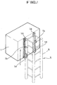
- Conventional elevator used in construction work is constructed such that the elevator is lifted upwards and downwards along the multi-stage assembled block as shown in Figs. 1 to 3.
- The
elevator car 1 has a pair ofguide rail rollers 1a for moving along aguide rail 6 of theblock 5. Twoguide rail rollers 1a are disposed at front and rear with respect to theguide rail 6, to guide the elevator upwards and downwards. Ahook 1b is disposed to guide theguide rail 6, for preventing deviation of theelevator car 1. - A plurality of
motors 2 andpinions 2a are employed in theelevator car 1, for actuating the elevator to be lifted in any desired direction. A plurality ofracks 4 is disposed at theblock 5 in the vertical direction. Driving of themotor 2 allows thepinions 2a to be rotated along theracks 4, so that theelevator car 1 is lifted upwards and downwards. - Especially the
elevator car 1 for use in construction work is required to attention safety since the elevator car is exposed at all times, and nevertheless the brake device is most important. Known elevator brake device are disclosed e.g. in US-A-5 353 895. - Conventional brake device of the elevator shows use of a
governor 3. The governor-braking device utilizes centrifugal force, in which thepinion 3 a of thegovernor 3 for brake device is engaged with therack 4 at the block. To the pinion a centrifugal weight is connected. - In case of fall or crash of the elevator due to abnormality such as malfunction or etc., the
pinion 3 a of thegovernor 3 of the elevator is rotated at high speed by therack 4, so that centrifugal weight being spread becomes held onto boss in the brake device to stop thepinion 3 a and to brake theelevator car 1. - Because lifting operation of the
elevator car 1 is dependent onpinion 2a andrack 4, the longer the elevator is used, the more fatigue the rack and pinion receive. The governor 3 intends to stop the elevator in crash but the rack weakened by fatigue practically receives a heavy impact. As a result, the gear teeth of therack 4 orpinion 3a of the governor 3 become damaged, resulting in fall or crash accident of the elevator. In a normal working condition, the elevator moves smoothly and impact does not harm on the passenger or luggage. However, in case of crash of elevator, heavy impact is accompanied with stop of the elevator by the governor, resulting in severe damage on luggage or passengers. - The building elevator operated by rope also utilizes the brake device by governor.
- This construction has a disadvantage of damage of passenger or luggage by heavy impact in stopping the elevator being fallen down.
- The present invention is derived to solve the disadvantage of the conventional art and to generate hydraulic pressure after detecting free fall or crash of the elevator and actuate a brake pad by hydraulic pressure, so that impact by sudden brake is relieved to maintain a stable brake interval and prevent the brake device from being damaged by heavy impact caused by sudden brake.
- The object of the present invention is accomplished by providing a hollow box-
shaped elevator car 1 for holding the passenger or luggage;block 5 including a pair ofguide rails 6 for guiding upwards and downwards theelevator car 1; a plurality ofracks 4 disposed at theblock 5 along the lifting direction in vertical; at least onemotor 2 tooth-engaged with at least onepinion 2a at theracks 4, for lifting upwards and downwards theelevator car 1; aclutch 12 for controlling power transmission to connect adriving shaft 19 to a drivenshaft 20 when thepinions racks 4 are rotated at high speed due to elevator drop;hydraulic pump 15 for generating hydraulic pressure from power transmission through a plurality oftransmission gears 13 when theclutch 12 delivers rotation; and a plurality ofhydraulic cylinders 17 for braking the elevator bybrake pad 18 in tight coupled with theguide rails 6 by hydraulic power from thehydraulic pump 15. - In crash of the elevator, the clutch actuates to operate the brake pad by hydraulic power from the hydraulic pump, thereby receiving impact and protecting passengers or luggage in the elevator.
- The elevator is stopped by friction brake with less impact onto the passenger or luggage, so that safety and reliability are improved.
- The present invention will be described in detail through use of the accompanying drawings in which:
- Fig. 1 is a perspective view of conventional elevator;
- Fig. 2 is a side view of the elevator used in construction work;
- Fig. 3 is a plane view of the elevator used in construction work;
- Fig. 4 is a side view of the elevator having a brake device acording to the present invention for use in construction work;
- Fig. 5 is a plane view of the brake device acording to the present invention;
- Fig. 6 is a sectional view of the clutch of the brake device according to the present invention;
- Figs. 7a and 7b are sectional views of the clutch of the brake device according to the present invention;
- Fig. 8 is a plane view of another embodiment of the brake device of the present invention; and
- Fig. 9 is a plane view of the building elevator of brake device of the present invention.
- The presently preferred embodiments of the invention will be best understood by reference to the drawings.
- Fig. 4 is a side view of the elevator having a brake device according to the present invention for use in construction work, and Fig. 5 is a plane view of the brake device according to the present invention.
- The
elevator car 1 is constituted to have a hollow box-shape to accommodate passengers or luggage. Theelevator car 1 is lifted upwards or downwards along theblock 5. - The
block 5 assembled in stacked includesguide rails 6 in vertical. Theguide rails 6 are crossed in zigzag, to form a guide rail for theelevator car 1. - A plurality of
racks 4 is disposed at one side of theblock 5 toward theelevator car 1. Theelevator car 1 includespinions 2a to rotate with the motor shaft of themotor 2. - The
pinion 2a is tooth-engaged with therack 4 at theguide rail 6. In driving themotor 2, therack 4 allows theelevator car 1 to lift upwards and downwards along rotational direction of thepinion 2a. - The
pinion 2a andmotor 2 are constructed to be a couple for anelevator car 1. - A
governor 3 can be also shown as the conventional one, for emergency. The governor 3 holds a weight when the weight is widened by centrifugal force, the governor 3 for brake device actuated. - The
pinion 3 a of governor 3 shows a toothed engagement withrack 4. A centrifugal weight is connected to thepinion 3a. When the elevator is being fallen, thepinion 3a in tooth-engagement with therack 4 is rotated at high speed, and the centrifugal weight being spread becomes held into boss in the brake device to stop thepinion 3a, so as to brake theelevator car 1. - The
elevator car 1 includes a hydraulic brake means 10. - The hydraulic brake means 10 comprises a
clutch 12, atransmission gear 13, ahydraulic pump 15,hydraulic cylinders 17 andbrake pads 18 actuated by friction. - The
clutch 12 has apinion 11 engaged with therack 4. - The
transmission gear 13 may include bevel gear, spur gear, helical gear or a combination thereof if transmission direction and frictional noise by tooth-engagement are considered. - A
cam 14 connects thehydraulic pump 15 and thetransmission gear 13 and rotation of thecam 14 generates hydraulic pressure from thehydraulic pump 15. - The hydraulic pressure is delivered to the
hydraulic cylinder 17 through thehydraulic line 16. A piston in motion by thehydraulic cylinder 17 actuates the brake pad. Thebrake pad 18 is constructed to be in contact with periphery of theguide rail 6 at theblock 5. Thehydraulic cylinder 17 andbrake pads 18 are made in couple. - When rotation of
pinion 11 is delivered to thehydraulic pump 15 through the clutch 12 and thetransmission gear 13, In the present invention, hydraulic pressure is generated from thehydraulic pump 15 to actuate thebrake pad 18 by thehydraulic cylinder 17. Accordingly, thebrake pad 18 in contact with theguide rail 6 causes brake by friction and as a result theelevator car 1 is stopped gradually. - Fig. 6 is a sectional view of the clutch of the brake device according to the present invention; and Figs. 7a to 7b are sectional views of the clutch of the brake device according to the present invention.
- The clutch 12 is held in the hydraulic brake means 10 and includes a driving
shaft 19 connected to thepinion 11, and a drivenshaft 20 on the same axle with the drivingshaft 19. The drivenshaft 20 employs a bearing 20a for supporting front end of the drivingshaft 19, and aclutch ring 27 at the outer periphery of the bearing 20a. In the inner periphery of theclutch ring 27, a plurality ofbosses 28 is radial disposed. At the drivingshaft 19, abalance weight 21 is disposed at the inner periphery of theclutch ring 27. - In the
balance weight 21, aweight 22 restrained by adjustingspring 24 and adjustinglever 23 is suspended until the centrifugal force reaches a predetermined value. Thebalance weight 21 also employs aplate spring 25 and astopper 26 for fixing the position ofweight 22. If theweight 22 is deviated from thebalance weight 21 by centrifugal force, theweight 22 is held at thestopper 26 of theplate spring 25 and cannot return to the original position. - In the constitution of the present invention, only the driving
shaft 19 and thepinion 11 of the clutch 12 are rotated during normal lifting operation of theelevator car 1. In the normal lifting operation of the elevator, although thepinion 11 is rotated along therack 4 and the rotational force is delivered to the drivingshaft 19, theweight 22 at the outer periphery of the drivingshaft 19 is not deviated but remains restraint by adjustinglever 23 because the centrifugal force due to the rotation is not heavy. Theweight 22 maintains the original position with thebalance weight 21 and rotates with the drivingshaft 19 while the drivenshaft 20 keeps suspended. - Accordingly, the present invention actuates the brake device in case of free fall of the elevator due to abnormality or malfunction, for example if the
pinion 2a and thegovernor 3 for lifting the elevator upwards and downwards are damaged. - In case of free fall of the elevator, rotational number of the
pinion 11 of a hydraulic brake device is more and more increased by acceleration. Over a predetermined increase of rotations of thepinion 11 causes a heavy centrifugal force on theweight 22 to exceed a limit over support force of the adjustinglever 23, thereby deviating from thebalance weight 21. - Fig. 7b shows a deviated state of the
weight 22. Thestopper 26 of the plate springs 25 roles to support theweight 22 and theweight 22 cannot return to the original position. Theweight 22 as deviated is held at any ofboss 28 of theclutch ring 27, to integrally rotate the drivingshaft 19 and drivenshaft 20. - When the rotational force of the driving
shaft 19 is delivered to the drivenshaft 20, as shown in Fig. 5, thehydraulic pump 15 generates hydraulic pressure through thetransmission gear 13 andcam 14. The hydraulic pressure is delivered to eachhydraulic cylinder 17 over thehydraulic line 16 to actuate thebrake pad 18 of the correspondinghydraulic cylinder 17 to cause friction on theguide rail 6 of theblock 5. - During friction, the
elevator car 1 performs stopping operation with less speed and is finally stopped. - Braking distance may be calculated by function of frictional coefficient between the
brake pad 18 and theguide rail 4, hydraulic power from thehydraulic cylinder 17, elevator weight, and falling speed of the elevator. The frictional coefficient, hydraulic power of thehydraulic cylinder 17 and falling speed of the elevator can be adjusted. The falling speed of the elevator can be controlled by escape speed of the clutch. - Fig. 8 is a plane view of another embodiment of the brake device of the present invention in which the contact position of the
brake pad 18 with theguide rail 6 can be modified. - The guide rails 6 are formed at the center of
block 5, in opposite. A pair of thehydraulic cylinders 17 and a pair of thebrake pads 18 are formed with respect to the guide rails 6. The cross-sectional of thebrake pads 18 andguide rails 6 may be circular, rectangular, lozenge-shaped or any other shape. - Fig. 9 is a plane view of the building elevator of brake device of the present invention.
- The
hydraulic brake device 10 is disposed in thecage 1c and thepinion 11 of thehydraulic brake device 10 is tooth-engaged with therack 4 formed at alifting path 1d. At opposite sides of thelifting path 1d theguide rails 6 are formed to have a pair of thebrake pads 18 and a pair of thehydraulic cylinders 17. - The same constitution of the brake device applies to the building elevator such that the
pinion 11 is rotated at high speed and the weight connected to thepinions 11 becomes widened from thepinion 11 to connect the driving shaft with the driven shaft, thereby generating hydraulic pressure from the hydraulic pump via transmission gear and cam in case of free fall of thecage 1c of building elevator. Thehydraulic cylinder 17 is actuated by hydraulic pressure and thebrake pad 18 brakes the building elevator. - In the present invention, when fall of the elevator is detected, hydraulic pressure actuates the brake pad to brake the elevator, thereby protecting the passengers from sudden impact.
- The brake device according to the present invention utilizes friction with less impact, so as to protect the passengers or luggage.
- Further, the present invention does not utilize the pinion of governor tooth-engaged with the rack with more potential fatigue but utilizes the guide rail and brake pad with less fatigue, thereby preventing the accident due to damage of the rack and pinion. Accordingly, the present invention has an effect to improve product reliability and durability.
Claims (3)
- An elevator with a brake device comprising:a hollow box-shaped elevator car (1) for holding the passenger or luggage;a block (5) including a pair of guide rails (6) for guiding upwards and downwards the elevator car (1);a plurality of racks (4) disposed at the block (5) along the lifting direction in vertical;at least one motor (2) tooth-engaged with at least one pinion (2a) at the racks (4), for lifting upwards and downwards the elevator car (1);a clutch (12) for controlling power transmission to connect a driving shaft (19) to a driven shaft (20) when the pinions engaged with the racks (4) are rotated at high speed by elevator drop;a hydraulic pump (15) for generating hydraulic pressure from power transmission through a plurality of transmission gears (13) when the clutch (12) delivers rotation; anda plurality of hydraulic cylinders (17) for braking the elevator by brake pad (18) in tight coupled with the guide rails (6) by hydraulic power from the hydraulic pump (15).
- An elevator with a brake device as claimed in claim 1, wherein said clutch (12) includes a driving shaft (19) having a pinion (11), driven shaft (20) for supporting the front end of the driving shaft (19), and a balance weight (21) having a weight (22) at the driving shaft (19), the driven shaft (20) includes a clutch ring (27) for surrounding the balance weight (21), and at the inner periphery of the clutch ring (27) the weight (22) is held on a plurality of bosses (28), the weight (22) deviated by centrifugal force and disposed for connecting a driving shaft (19) and a driven shaft (20).
- An elevator with a brake device as claimed in claim 2, wherein an adjusting lever (23) is disposed in the balance weight (21) for hanging the weight (22), an adjusting spring (24) is disposed at the rear end of the adjusting lever (23) for controlling the centrifugal force of the weight (22), and a plate spring (25) is disposed at one side of the balance weight (21) with a stopper (26) for preventing the weight (22) from being returned to the original position.
Applications Claiming Priority (3)
| Application Number | Priority Date | Filing Date | Title |
|---|---|---|---|
| KR1020000020394A KR100354380B1 (en) | 2000-04-18 | 2000-04-18 | Brake apparatus for elevator |
| KR2000020394 | 2000-04-18 | ||
| PCT/KR2000/001538 WO2001079103A1 (en) | 2000-04-18 | 2000-12-27 | Brake device for elevator |
Publications (2)
| Publication Number | Publication Date |
|---|---|
| EP1274643A1 EP1274643A1 (en) | 2003-01-15 |
| EP1274643B1 true EP1274643B1 (en) | 2006-12-20 |
Family
ID=19665209
Family Applications (1)
| Application Number | Title | Priority Date | Filing Date |
|---|---|---|---|
| EP00989017A Expired - Lifetime EP1274643B1 (en) | 2000-04-18 | 2000-12-27 | Brake device for elevator |
Country Status (9)
| Country | Link |
|---|---|
| US (1) | US6830132B1 (en) |
| EP (1) | EP1274643B1 (en) |
| JP (1) | JP2003535001A (en) |
| KR (1) | KR100354380B1 (en) |
| CN (1) | CN1201996C (en) |
| AT (1) | ATE348781T1 (en) |
| AU (2) | AU2001225561B2 (en) |
| DE (1) | DE60032518D1 (en) |
| WO (1) | WO2001079103A1 (en) |
Cited By (1)
| Publication number | Priority date | Publication date | Assignee | Title |
|---|---|---|---|---|
| CN107337063A (en) * | 2016-02-08 | 2017-11-10 | 刘伟强 | Self-propelled elevator and elevator brake system |
Families Citing this family (45)
| Publication number | Priority date | Publication date | Assignee | Title |
|---|---|---|---|---|
| US7311179B1 (en) * | 2004-01-20 | 2007-12-25 | Franklin Samuel H | Elevator dampening system |
| US7975807B2 (en) * | 2004-01-20 | 2011-07-12 | Franklin Samuel H | Elevator climbing system |
| US7909142B2 (en) * | 2006-05-19 | 2011-03-22 | Hydro-Mobile Inc. | Braking device for elevating platform assembly |
| US20090026898A1 (en) * | 2007-07-25 | 2009-01-29 | Mcintosh Steven C | Enhanced Computer Rack Having An Integrated Lift Rail And/Or Tool Design |
| US8210319B2 (en) * | 2007-08-31 | 2012-07-03 | John W. Boyd | Hydraulic elevating platform assembly |
| US20090129905A1 (en) * | 2007-11-20 | 2009-05-21 | International Business Machines Corporation | Portable end-to-end installation and removal service lift tool for rack mounted it equipment |
| NL2001941C (en) * | 2008-08-29 | 2010-03-11 | Houtveen Beheer Achterveld B V | VEHICLE LIFT. |
| US8714312B2 (en) | 2009-06-19 | 2014-05-06 | James L. Tiner | Elevator safety rescue system |
| US8191689B2 (en) | 2009-06-19 | 2012-06-05 | Tower Elevator Systems, Inc. | Elevator safety rescue system |
| US20110061976A1 (en) * | 2009-09-17 | 2011-03-17 | Tiner James L | Battery counterweighted elevator |
| KR101239191B1 (en) * | 2010-09-08 | 2013-03-12 | 한국모노레일주식회사 | Safety and emergency brake system for the tower structure maintenance system |
| CN102070059A (en) * | 2011-01-04 | 2011-05-25 | 张向阳 | Hydraulic speed limiting elevator |
| KR101266472B1 (en) | 2011-05-20 | 2013-05-23 | 조부현 | Method for culturing rhizopus microsporus var oliggosporus using rice |
| CN102718099A (en) * | 2012-05-28 | 2012-10-10 | 吴江市精工铝字制造厂 | Safety device for elevator |
| US9546021B2 (en) * | 2013-02-10 | 2017-01-17 | Diverse Holdings, Llc | Apparatus for storing, transporting and distributing kegs |
| CN104108661B (en) * | 2013-04-19 | 2017-02-08 | 中国有色(沈阳)冶金机械有限公司 | Combined lifting system of aluminum electrolysis multi-functional crane slag removing device |
| ITTV20130057A1 (en) * | 2013-04-23 | 2014-10-24 | Tarcisio Scomparin | "ELEVATOR AND TRANSLATOR SYSTEM WITH A PORTAL STRUCTURE THAT EMPLOYS RACKS AND MORE VERTICAL AND HORIZONTAL TRAVEL LINES OF AT LEAST ONE TRANSPORT CABIN OF PEOPLE AND THINGS FOR THE OVERCOME OF OBSTACLES RAISED AND NOT." |
| CN103373369B (en) * | 2013-08-02 | 2016-02-03 | 金培赶 | A kind of hypervelocity automatic brake arrangement |
| KR101528847B1 (en) * | 2013-11-14 | 2015-06-15 | 건설용리프트협동조합 | The Lift crash deceleration device |
| US10017359B2 (en) * | 2014-01-08 | 2018-07-10 | Modern Concepts Outdoors Llc | Rack and roller pinion lift system |
| CN103754721B (en) * | 2014-01-21 | 2016-08-17 | 刘小木 | Elevator car manual brake set |
| DE102014101655A1 (en) * | 2014-02-11 | 2015-08-13 | Konecranes Plc | Hoist with hysteresis clutch |
| EP2913287B1 (en) | 2014-02-26 | 2018-01-03 | Otis Elevator Company | Governor for controlling the speed of a hoisted object relative to a guide member |
| CN104340804A (en) * | 2014-10-30 | 2015-02-11 | 国家电网公司 | Emergency braking device for elevator |
| US9975733B2 (en) * | 2015-01-26 | 2018-05-22 | Kevin Cunningham | Elevator safety device |
| ITUA20163368A1 (en) * | 2016-05-12 | 2017-11-12 | Marchesini Group Spa | STABILIZATION DEVICE FOR STABILIZING ITEMS DURING THEIR LIFTING AND GROUPING |
| CN107265241B (en) * | 2017-07-25 | 2023-06-13 | 波士顿电梯(湖州)有限公司 | Elevator torsional spring braking device |
| CN107200252A (en) * | 2017-08-01 | 2017-09-26 | 南昌大学 | One kind braking disc type used during elevator falling, which slows down, stops falling unit |
| NL2019467B1 (en) * | 2017-08-30 | 2019-03-11 | Raxtar B V | Fall protection for a lift and lift equipped with fall protection |
| CN108042933A (en) * | 2017-11-15 | 2018-05-18 | 南宁晟景工程咨询有限公司 | A kind of escape device for preventing from sliding at a high speed |
| CN108079448A (en) * | 2017-11-15 | 2018-05-29 | 南宁晟景工程咨询有限公司 | A kind of building escape device |
| EP3781069B1 (en) * | 2018-04-16 | 2025-04-30 | Covidien LP | Robotic surgical systems and robotic arm carts thereof |
| CN109132772B (en) * | 2018-08-29 | 2020-08-28 | 合肥市迅立达电梯有限公司 | An elevator overspeed protection device |
| DE102019210531A1 (en) * | 2019-07-17 | 2021-01-21 | Thyssenkrupp Elevator Innovation And Operations Ag | Elevator system |
| RU2718706C1 (en) * | 2019-11-07 | 2020-04-14 | Акционерное общество "Щербинский Лифтостроительный Завод" | Catcher |
| CN111717763B (en) * | 2020-07-02 | 2021-07-09 | 苏州银海机电科技有限公司 | Stable lifting mechanism of box elevator |
| CN111847180B (en) * | 2020-07-31 | 2021-04-27 | 广西嘉立机械租赁有限公司 | A construction elevator safety protection equipment for free-fall emergency stop |
| CN112456269B (en) * | 2020-11-25 | 2022-05-17 | 广州广日电梯工业有限公司 | Intelligent braking system |
| KR102286398B1 (en) * | 2020-12-04 | 2021-08-04 | 장무기 | Elevation Drive Assembly of Tower Crane Cage |
| CN112678646B (en) * | 2021-01-11 | 2022-04-12 | 安川双菱电梯有限公司 | Elevator with multiple safety protection functions |
| DE102021204833A1 (en) * | 2021-05-12 | 2022-11-17 | Zf Friedrichshafen Ag | transport system |
| CN114772419A (en) * | 2022-03-23 | 2022-07-22 | 深圳市永达电子信息股份有限公司 | Elevator control system and method based on rack transmission |
| CN115215227B (en) * | 2022-07-15 | 2024-10-18 | 南通恒立机械设备有限公司 | Anti-drop structure of single arm of force promotes press |
| CN115924680B (en) * | 2023-03-01 | 2025-12-26 | 浙江智菱科技有限公司 | An elevator fall prevention device |
| CN119389947A (en) * | 2025-01-03 | 2025-02-07 | 贵州交通职业技术学院 | Hoisting device for bridge member |
Family Cites Families (17)
| Publication number | Priority date | Publication date | Assignee | Title |
|---|---|---|---|---|
| US1634865A (en) * | 1926-06-23 | 1927-07-05 | Walter C Barnes | Core drill |
| US3415343A (en) * | 1967-04-18 | 1968-12-10 | Alimak Verken Ab | Catch apparatus for the cages of scaffold elevators and the like |
| SE360634B (en) * | 1972-02-24 | 1973-10-01 | Linden Alimak Ab | |
| US3934682A (en) * | 1972-11-23 | 1976-01-27 | Hedstrom Ture E | Safety device for lifts, hoists and like apparatus |
| US3924710A (en) * | 1972-11-30 | 1975-12-09 | Harsco Corp | Rack and pinion hoist |
| GB1495543A (en) * | 1973-10-24 | 1977-12-21 | Wickham & Co Ltd D | Hoists |
| JPS5831808B2 (en) * | 1977-11-09 | 1983-07-08 | 株式会社東芝 | closed switchboard |
| US4516663A (en) * | 1982-03-15 | 1985-05-14 | Harsco Corporation | Safety device |
| US4856623A (en) | 1982-12-06 | 1989-08-15 | Romig Jr Byron A | Overspeed brake |
| KR870011027A (en) * | 1986-05-15 | 1987-12-19 | 로버어트 이이 그린스틴 | Elevator and its control method |
| DE3706802A1 (en) * | 1987-03-03 | 1988-09-15 | Karlheinz Menkhoff | Speed limiter with safety brakes, e.g. for lift cars |
| KR910008224Y1 (en) * | 1989-05-09 | 1991-10-12 | 주식회사 일광산업기계 | Elevator safety brake |
| JP2785061B2 (en) * | 1990-03-30 | 1998-08-13 | 株式会社竹中工務店 | High-speed shared cargo elevator for construction |
| CA2072187C (en) | 1992-06-23 | 1996-09-03 | Dermot Camack | Emergency braking systems for hoists |
| US5366045A (en) | 1993-09-03 | 1994-11-22 | Eaton Corporation | Brake mechanism for a storage and retrieval vehicle |
| JP3846750B2 (en) | 1996-11-29 | 2006-11-15 | 三和テッキ株式会社 | Elevator descent speed control device |
| NL1007160C2 (en) * | 1997-09-29 | 1999-03-30 | Inventions & Dev Holland B V | Linear actuator. |
-
2000
- 2000-04-18 US US10/203,317 patent/US6830132B1/en not_active Expired - Fee Related
- 2000-04-18 KR KR1020000020394A patent/KR100354380B1/en not_active Expired - Fee Related
- 2000-12-27 JP JP2001576372A patent/JP2003535001A/en active Pending
- 2000-12-27 WO PCT/KR2000/001538 patent/WO2001079103A1/en not_active Ceased
- 2000-12-27 DE DE60032518T patent/DE60032518D1/en not_active Expired - Fee Related
- 2000-12-27 AU AU2001225561A patent/AU2001225561B2/en not_active Ceased
- 2000-12-27 AT AT00989017T patent/ATE348781T1/en not_active IP Right Cessation
- 2000-12-27 EP EP00989017A patent/EP1274643B1/en not_active Expired - Lifetime
- 2000-12-27 AU AU2556101A patent/AU2556101A/en active Pending
- 2000-12-27 CN CNB008193436A patent/CN1201996C/en not_active Expired - Fee Related
Cited By (2)
| Publication number | Priority date | Publication date | Assignee | Title |
|---|---|---|---|---|
| CN107337063A (en) * | 2016-02-08 | 2017-11-10 | 刘伟强 | Self-propelled elevator and elevator brake system |
| CN107337063B (en) * | 2016-02-08 | 2020-06-30 | 刘伟强 | Self-propelled elevator and elevator braking system |
Also Published As
| Publication number | Publication date |
|---|---|
| JP2003535001A (en) | 2003-11-25 |
| KR100354380B1 (en) | 2002-09-28 |
| US6830132B1 (en) | 2004-12-14 |
| EP1274643A1 (en) | 2003-01-15 |
| DE60032518D1 (en) | 2007-02-01 |
| ATE348781T1 (en) | 2007-01-15 |
| AU2001225561B2 (en) | 2004-02-26 |
| WO2001079103A1 (en) | 2001-10-25 |
| CN1450973A (en) | 2003-10-22 |
| CN1201996C (en) | 2005-05-18 |
| AU2556101A (en) | 2001-10-30 |
| KR20010096316A (en) | 2001-11-07 |
Similar Documents
| Publication | Publication Date | Title |
|---|---|---|
| AU2001225561B2 (en) | Brake device for elevator | |
| CN103459289B (en) | Lift appliance | |
| US6360847B1 (en) | Elevator system and speed governing apparatus | |
| EP2571799B1 (en) | Integrated elevator safety system | |
| CA2013259C (en) | Elevator traction sheave brake | |
| AU777664B2 (en) | Method for braking a traction sheave elevator, traction sheave elevator and use of an emergency power supply | |
| EP3309104B1 (en) | Method for avoiding unwanted safety gear tripping in an elevator system, controller adapted to perform such a method, governor brake and elevator system each having such a controller | |
| JPWO2018030155A1 (en) | Elevator equipment | |
| JP2019156567A (en) | Emergency stop device and elevator | |
| EP3342740A1 (en) | A method for avoiding unwanted safety gear tripping in a safety stopping system of an elevator system and a safety stopping system | |
| WO2014097373A1 (en) | Elevator device | |
| KR20080092376A (en) | Elevator and elevator brake | |
| CN112777446A (en) | Elevator with a movable elevator car | |
| EP2524890B1 (en) | Elevator with positon dependent braking force | |
| US6296080B1 (en) | Variable traction mechanism for rotary actuated overspeed safety device | |
| JP3944482B2 (en) | Elevator equipment | |
| EP2001783B1 (en) | Arrangement for stopping an elevator car in an emergency braking situation, and elevator | |
| EP1086921B1 (en) | Safety device of elevator | |
| JP4115396B2 (en) | Emergency brake device for elevator | |
| EP3630664B1 (en) | Arrangement in an elevator for stopping uncontrolled movement of the elevator car | |
| KR200243892Y1 (en) | Brake apparatus for elevator | |
| IT202100003905A1 (en) | Emergency brake | |
| JP2019196241A (en) | Speed governor and elevator | |
| KR200195654Y1 (en) | Brake apparatus for elevator | |
| JP2002128414A (en) | Elevator terminal floor reduction gear |
Legal Events
| Date | Code | Title | Description |
|---|---|---|---|
| PUAI | Public reference made under article 153(3) epc to a published international application that has entered the european phase |
Free format text: ORIGINAL CODE: 0009012 |
|
| 17P | Request for examination filed |
Effective date: 20020920 |
|
| AK | Designated contracting states |
Kind code of ref document: A1 Designated state(s): AT BE CH CY DE DK ES FI FR GB GR IE IT LI LU MC NL PT SE TR |
|
| AX | Request for extension of the european patent |
Free format text: AL;LT;LV;MK;RO;SI |
|
| RBV | Designated contracting states (corrected) |
Designated state(s): AT BE CH CY DE FR GB LI SE |
|
| GRAP | Despatch of communication of intention to grant a patent |
Free format text: ORIGINAL CODE: EPIDOSNIGR1 |
|
| RBV | Designated contracting states (corrected) |
Designated state(s): AT DE FR GB SE |
|
| GRAS | Grant fee paid |
Free format text: ORIGINAL CODE: EPIDOSNIGR3 |
|
| GRAA | (expected) grant |
Free format text: ORIGINAL CODE: 0009210 |
|
| AK | Designated contracting states |
Kind code of ref document: B1 Designated state(s): AT DE FR GB SE |
|
| PG25 | Lapsed in a contracting state [announced via postgrant information from national office to epo] |
Ref country code: AT Free format text: LAPSE BECAUSE OF FAILURE TO SUBMIT A TRANSLATION OF THE DESCRIPTION OR TO PAY THE FEE WITHIN THE PRESCRIBED TIME-LIMIT Effective date: 20061220 |
|
| REG | Reference to a national code |
Ref country code: GB Ref legal event code: FG4D |
|
| REF | Corresponds to: |
Ref document number: 60032518 Country of ref document: DE Date of ref document: 20070201 Kind code of ref document: P |
|
| REG | Reference to a national code |
Ref country code: SE Ref legal event code: TRGR |
|
| PG25 | Lapsed in a contracting state [announced via postgrant information from national office to epo] |
Ref country code: DE Free format text: LAPSE BECAUSE OF NON-PAYMENT OF DUE FEES Effective date: 20070703 |
|
| EN | Fr: translation not filed | ||
| PLBE | No opposition filed within time limit |
Free format text: ORIGINAL CODE: 0009261 |
|
| STAA | Information on the status of an ep patent application or granted ep patent |
Free format text: STATUS: NO OPPOSITION FILED WITHIN TIME LIMIT |
|
| 26N | No opposition filed |
Effective date: 20070921 |
|
| GBPC | Gb: european patent ceased through non-payment of renewal fee |
Effective date: 20070320 |
|
| PG25 | Lapsed in a contracting state [announced via postgrant information from national office to epo] |
Ref country code: FR Free format text: LAPSE BECAUSE OF FAILURE TO SUBMIT A TRANSLATION OF THE DESCRIPTION OR TO PAY THE FEE WITHIN THE PRESCRIBED TIME-LIMIT Effective date: 20070810 Ref country code: GB Free format text: LAPSE BECAUSE OF NON-PAYMENT OF DUE FEES Effective date: 20070320 |
|
| PG25 | Lapsed in a contracting state [announced via postgrant information from national office to epo] |
Ref country code: FR Free format text: LAPSE BECAUSE OF FAILURE TO SUBMIT A TRANSLATION OF THE DESCRIPTION OR TO PAY THE FEE WITHIN THE PRESCRIBED TIME-LIMIT Effective date: 20061220 |
|
| PGFP | Annual fee paid to national office [announced via postgrant information from national office to epo] |
Ref country code: SE Payment date: 20101229 Year of fee payment: 11 |
|
| REG | Reference to a national code |
Ref country code: SE Ref legal event code: EUG |
|
| PG25 | Lapsed in a contracting state [announced via postgrant information from national office to epo] |
Ref country code: SE Free format text: LAPSE BECAUSE OF NON-PAYMENT OF DUE FEES Effective date: 20111228 |