EP1273916A1 - Measuring method for immunochromatographic test strip - Google Patents
Measuring method for immunochromatographic test strip Download PDFInfo
- Publication number
- EP1273916A1 EP1273916A1 EP01917845A EP01917845A EP1273916A1 EP 1273916 A1 EP1273916 A1 EP 1273916A1 EP 01917845 A EP01917845 A EP 01917845A EP 01917845 A EP01917845 A EP 01917845A EP 1273916 A1 EP1273916 A1 EP 1273916A1
- Authority
- EP
- European Patent Office
- Prior art keywords
- light
- immunochromatography test
- test piece
- mixing rod
- optical system
- Prior art date
- Legal status (The legal status is an assumption and is not a legal conclusion. Google has not performed a legal analysis and makes no representation as to the accuracy of the status listed.)
- Withdrawn
Links
Images




Classifications
-
- G—PHYSICS
- G01—MEASURING; TESTING
- G01N—INVESTIGATING OR ANALYSING MATERIALS BY DETERMINING THEIR CHEMICAL OR PHYSICAL PROPERTIES
- G01N21/00—Investigating or analysing materials by the use of optical means, i.e. using sub-millimetre waves, infrared, visible or ultraviolet light
- G01N21/84—Systems specially adapted for particular applications
- G01N21/8483—Investigating reagent band
Definitions
- the present invention relates to a device for measuring immunochromatography test pieces.
- antibodies which provoke a antigen or antibody reaction with antigens (or antibodies) in a subject (sample) are previously coated in strips onto prescribed positions of an immunochromatography test piece.
- the antigens (or antibodies) in the subject are dissolved out using a developer solution, and are caused to impregnate into the immunochromatography test piece, whereupon the antigens (or antibodies) in the subject are trapped by an antigen or antibody reaction in the region of the antigens (or antibodies) coated onto the immunochromatography test piece.
- the quantity trapped is the total amount of that antigen (or antibody) in the subject
- Immunochromatography analysis can be used for measuring extremely small quantities, compared to standard colorimetric methods.
- Japanese Patent Laid-open No. H7-5110 discloses a measuring device for measuring the concentration of a specific material in a subject from an immunochromatography test piece after development and dying of the subject.
- light from an LED is irradiated onto an immunochromatography test piece, the light reflected from the immunochromatography test piece is detected by a CCD color image sensor, and the degree of coloration is identified.
- a light-emitting element such as an LED
- the amount of light irradiated onto the immunochromatography test piece is low, and since the colored region of the immunochromatography test piece is very small (approximately 0.5 mm), it is difficult to detect the colored region.
- a light-emitting tube such as a sodium tube, fluorescent tube, or the like, for the light source, has been considered, but in such cases, the device would become large in size.
- the present invention was devised with the foregoing in view, an object thereof being to provide a measuring device for immunochromatography test pieces whereby detection of colored regions of an immunochromatography test piece can be performed reliably, without increasing the size of the device.
- the measuring device for immunochromatography test pieces is a measuring device for immunochromatography test pieces, comprising an irradiation optical system for irradiating measurement light onto immunochromatography test pieces; and a detection optical system for detecting light from the immunochromatography test pieces due to irradiation of the measurement light; characterized in that the irradiation optical system comprises a light-emitting element, and a mixing rod for mixing the light output from the light-emitting element, the light exiting from the mixing rod being irradiated onto the immunochromatography test piece as the measurement light; and the detection optical system comprises an imaging lens for forming an image of the light from the immunochromatography test piece, and an imaging element disposed in a position where the light from the immunochromatography test piece is formed into an image by the imaging lens, the light transmitted by the immunochromatography test piece being detected by the imaging element.
- the irradiation optical system comprises a light-emitting element, and a mixing rod for mixing the light output from the light-emitting element, the
- an irradiation optical system and a detection optical system comprising a light-emitting element, and a mixing rod for mixing the light output from the light-emitting element, the light exiting from the mixing rod being irradiated onto the immunochromatography test piece as the measurement light; and the detection optical system comprising an imaging lens for forming an image of the light from the immunochromatography test piece, and an imaging element disposed in a position where the light from the immunochromatography test piece is formed into an image by the imaging lens, the light from the immunochromatography test piece being received and detected by the imaging element.
- the light output by the light-emitting element is mixed by the mixing rod and then irradiated onto the immunochromatography test piece, attenuation of light by the light-emitting element is suppressed, and the amount of light irradiated onto the immunochromatography test piece is increased. Consequently, the colored portion of the immunochromatography test piece can be detected reliably by the imaging element. Moreover, since a light-emitting element is used as a light source, it is possible to suppress increase in the size of the device.
- the measuring device for immunochromatography test pieces according to the present invention may also be characterized in that diffusing means for diffusing the light input to the mixing rod and the light exiting from the mixing rod are further provided on the light input side and light output side of the mixing rod.
- the light irradiated onto the immunochromatography test pieces is approximately equalized. Thereby, the colored region of the immunochromatography test pieces can be detected with even greater reliability by the imaging element.
- the measuring device for immunochromatography test pieces according to the present invention may also be characterized in that the immunochromatography test piece is held in a casing having an observation window; the irradiation optical system irradiating the light emitted from the mixing rod towards the observation window, as the measurement light; and the surface area of the light output face of the mixing rod being set to a larger area than the surface area of the observation window.
- the immunochromatography test piece is held in a casing having an observation window and the irradiation optical system irradiates the light emitted from the mixing rod as measurement light onto the observation window, and since the surface area of the light output face of the mixing rod is greater than the surface area of the observation window, the light irradiated onto the position corresponding to the observation window of the immunochromatography test piece is approximately equalized. Thereby, the colored region of the immunochromatography test piece can be detected with even greater reliability by the imaging element.
- a measuring device for immunochromatography test pieces relating to embodiments of the present invention is now described with reference to the drawings.
- similar elements or elements having similar functions are similarly labelled, and duplicated description thereof is omitted.
- a measuring device 1 for immunochromatography test pieces relating to a first embodiment is described.
- the measuring device 1 comprises an irradiating optical system 20 for irradiating measurement light onto an immunochromatography test piece 10, and a detection optical system 30 for detecting light from an immunochromatography test piece 10 by irradiation of the measurement light.
- the irradiation optical system 20 comprises a light-emitting element 21 and a mixing rod 22.
- the detection optical system 30 comprises an aperture 31, a convex lens 33 forming an imaging lens, and a CCD image sensor 36 forming an imaging element.
- the immunochromatography test piece 10 has a long rectangular shape and is made from a material such as a nitrocellulose membrane, or filter paper, or the like. This immunochromatography test piece 10 is held inside a casing having a long rectangular shape in plan view, and a subject application window 12, observation window 13 and control window 14 are provided extending in the direction of the longer side in the casing 11.
- the immunochromatography test piece 10 comprises a subject application section 15 provided in a position corresponding to the subject application window 12, and detecting sections 16, 17 provided in positions corresponding to the observation window 13 and control window 14.
- the detecting section 16 has a line shape (or band shape) formed by coating respective antigens (or antibodies) which react with antigens (or antibodies) in the subject, and causing same to solidify.
- the casing 11 which holds the immunochromatography test piece 10 is held by holding means (not illustrated).
- the observation window 13 has a size of 4 mm ⁇ 8 mm, for example.
- the subject is applied dropwise via the subject application window 12 onto the subject application section 15 of the immunochromatography test piece 10.
- the antigens (or antibodies) in the subject couple with the indicator dye and the indicator dye coupled with the antigens (or antibodies) in the subject, as well as unreacted indicator dye, travel in the longitudinal direction of the immunochromatography test piece 10. Supposing that the subject contains antigens, then it is assumed that the antigens will undergo an antigen/antibody reaction with the respective detecting sections.
- the antigens in the subject and the antigens fixed to the detecting section 16 react specifically and a line-shaped pattern 18 colored by the indicator dye is formed in the detecting section 16 which has reacted.
- This colored line-shaped pattern 18 is formed extending in a direction intersecting (for example, orthogonally) with the direction of travel of the antigens (or antibodies) of the subject in the immunochromatography test piece 10, and it can be observed by means of the observation window 13.
- the light-emitting element 21 comprises a plurality of LEDs having different light emission wavelengths, in the present embodiment, a blue LED 21B and a red LED 21R. If the line-shaped pattern 18 formed by the antigen/antibody reaction is colored red, then the blue LED 21B is caused to emit light. If the line-shaped pattern 18 formed by the antigen/antibody reaction is colored blue, then the red LED 21R is caused to emit light.
- the mixing rod 22 is a square-shaped (or circular-shaped) rod made from transparent acrylic resin for mixing the light output by the light-emitting element 21 (blue LED 21B or red LED 21R), and it has a light input face and a light output face at the respective ends thereof.
- the aforementioned light-emitting element 21 is positioned on the light input face side of the mixing rod 22.
- An immunochromatography test piece 10 (casing 11) is positioned on the light output face side of the mixing rod 22. More specifically, the immunochromatography test piece 10 (casing 11) is positioned opposing the light output face of the mixing rod 22 in such a manner that the observation window 13 of the casing 11 coincides with the light output face of the mixing rod 22.
- the light output face of the mixing rod 22 has a size of 8 mm x 14 mm, and the surface area of the light output face of this mixing rod 22 is set to a larger area than the surface area of the opening in the observation window 13 of the casing 11.
- Diffusion plates 23, 24 forming diffusing means are provided at the light input face and light output face of the mixing rod 22, in a state of contact with the light input face and light output face of the mixing rod 22.
- These diffusing plates 23, 24 are made from opaque acrylic resin. Instead of providing diffusing plates 23, 24, it is also possible to form the actual light input face and light output face of the mixing rod 22 into ground glass faces in order to provide diffusing means.
- the light output from the light-emitting element 21 (blue LED 21B or red LED 21R) is diffused by the diffusing plate 23 and then enters into the mixing rod 22 via the light input face of the mixing rod 22.
- the light that has entered the mixing rod 22 is mixed by being fully reflected at the side faces of the mixing rod 22 whilst it is propagated therein, and this mixed light arrives at the light output face of the mixing rod 22.
- the light arriving at the light output face of the mixing rod 22 is diffused by the diffusing plate 24, and is then irradiated as measurement light from the rear face of the observation window 13 of the casing 11 in the direction of the immunochromatography test piece 10 (observation window 13 of the casing 11).
- the aperture 31 has a restricting hole section 32.
- the transmission light that is transmitted through the immunochromatography test piece 10 (casing 11) due to irradiation of measurement light and exits from the observation window 13 is restricted by the restricting hole section 32 of the aperture 31.
- the convex lens 33 forms an image of the transmission light from the immunochromatography test piece 10 (casing 11) which is incident thereon via the restricting hole section 32 of the aperture 31.
- the CCD image sensor 36 has a light receiving face 37, which is situated at the position where an image of the transmission light from the immunochromatography test piece 10 (casing 11) is formed by the convex lens 33.
- Light-receiving elements are provided in a one-dimensional or two-dimensional array on the light-receiving face 37.
- the CCD image sensor 36 detects the transmission light from the immunochromatography test piece 10 by capturing the image formed by the convex lens 33 on the light receiving face 37.
- the concentration of the subject is determined as described below, on the basis of the output signal from the CCD image sensor 36.
- a light absorption profile of the transmission light of the immunochromatography test piece 10 is created as illustrated in Fig. 2, on the basis of the output signal intensity from the CCD image sensor 36 and the position of the light-receiving element (channel) of the CCD image sensor 36.
- the light absorption ABS is calculated by means of the following equation (1), taking T o as the output signal intensity at a position in the created absorption profile corresponding to a portion of the immunochromatography test piece 10 that is not colored, and taking T i as the output light intensity at a position corresponding to a colored region thereof (line-shaped pattern 18).
- T o the output signal intensity at a position in the created absorption profile corresponding to a portion of the immunochromatography test piece 10 that is not colored
- T i the output light intensity at a position corresponding to a colored region thereof
- the total quantity (concentration) of antibodies or antigens contained in the subjected is derived from the light absorption ABS, by referring to a previously created quantity characteristics graph.
- an irradiation optical system 20 and a detection optical system 30 are provided in the measuring device 1.
- the irradiation optical system 20 comprises a light-emitting element 21 (blue LED 21B or red LED 21R), and a mixing rod 22, and the light emitted from the mixing rod 22 is irradiated as measurement light onto the immunochromatography test piece 10 (casing 11).
- the detection optical system 30 comprises a convex lens 33 and CCD image sensor 36, and detects transmission light from the immunochromatography test piece 10 (casing 11) by means of the CCD image sensor 36.
- the light output by the light-emitting elements 21 is mixed by the mixing rod 22 before being irradiated onto the immunochromatography test piece 10 (casing 11), attenuation of the light from the light-emitting elements 21 is suppressed, and the amount of light irradiated onto the immunochromatography test piece 10 is increased. Consequently, the CCD image sensor 36 is able reliably to detect a line-shaped pattern 18 formed by coloration of the immunochromatography test piece 10. Moreover, since light-emitting elements 21 (a blue LED 21B and a red LED 21R) are used, it is possible to suppress increase in the size of the measuring device 1.
- the measuring device 1 since diffusing plates 23, 24 are provided at the light input face and light output face of the mixing rod 22, the light irradiated onto the immunochromatography test piece 10 (casing 11) is approximately equalized. Thereby, it is possible to perform detection of the line-shaped pattern 18 in the immunochromatography test piece 10 by means of the CCD image sensor 36 with even greater reliability.
- the measuring device 1 since the surface area of the light output face of the mixing rod 22 is greater than the surface area of the observation window 13 of the casing 11, the light irradiated onto a position corresponding to the observation window 13 of the immunochromatography test piece 10 will be further equalized. Thereby, the detection of the line-shaped pattern 18 in the immunochromatography test piece 10 by means of the CCD image sensor 36 can be performed with even greater reliability.
- the irradiation optical system 20 and detection optical system 30 in the measuring device 1 are positioned in such a manner that the CCD image sensor 36 receives the transmission light of the measurement light irradiated onto the immunochromatography test piece 10, and the light absorption of the line-shaped pattern 18 formed by coloration is measured on the basis of the transmission light received by the CCD image sensor 36.
- the degree of coloration of the line-shaped pattern 18 formed in the immunochromatography test piece 10 can be measured simply and very accurately, and the total amount (concentration) of antigens or antibodies contained in the subject can be measured precisely.
- the measuring device 101 for immunochromatography test pieces relating to a second embodiment of the present invention differs from the measuring device 1 relating to the first embodiment in that the imaging lens is a cylindrical lens.
- the measuring device 101 comprises an aperture 131, and a cylindrical lens 133 forming an imaging lens.
- This cylindrical lens 133 is disposed in such a manner that the direction of the generating line of the curved face of the cylindrical lens 133 intersects (orthogonally, for example) with the direction of travel of the antigens (or antibodies) of the subject in the immunochromatography test piece 10, in other words, in such a manner that it faces the direction of extension of the line-shaped pattern 18 formed by coloration of the immunochromatography test piece 10.
- the aperture 131 is disposed on the light input face side of the cylindrical lens 133.
- a long rectangular slit 132 extending in the direction of the generating line of the curved face of the cylindrical lens 133 is formed in this aperture 131.
- An aperture 134 for restricting the input of light other than light from the observation window 13 to the cylindrical lens 133 is provided on the light output side of the immunochromatography test piece 10 (casing 11).
- a hole section 135 for passing transmission light from the immunochromatography test piece 10 (casing 11) is provided in the aperture 134.
- the measuring device 101 having the foregoing composition provides the same action and beneficial effects as the measuring device 1 relating to the first embodiment and is able reliably to detect a line-shaped pattern 18 formed by coloration of an immunochromatography test piece 10, by means of the CCD image sensor 36. Moreover, since light-emitting elements 21 (blue LED 21B or red LED 21R) are used as light sources, it is possible to prevent increase in the size of the measuring device 101.
- the measuring device 101 has a cylindrical lens 133 as an imaging lens, and this cylindrical lens 133 is disposed so that the direction of the generating line of the curved face thereof intersects with the direction of travel of the antigens or antibodies in the immunochromatography test piece 10, and it forms an image of the line-shaped pattern 18 formed in a direction intersecting with the direction of travel of the antigens or antibodies, on the CCD image sensor 36, due to irradiation of measurement light.
- light that is parallel to the direction of travel of the antigens or antibodies in the immunochromatography test piece 10 is formed as an image on the CCD image sensor 36, and light that is orthogonal to the direction of travel of the antigens or antibodies in the immunochromatography test piece 10 is defocused and equalized.
- an aperture 131 formed with a long rectangular slit 132 extending in the direction of the generating line of the curved face of the cylindrical lens 133 is disposed on the light input face side of the cylindrical lens 133, it is possible to form an image having little aberration on at the CCD image sensor 36.
- the measuring device 201 for immunochromatography test pieces relating to a third embodiment differs from the measuring device 101 relating to the second embodiment and second embodiment in that the light path is constituted in a bent fashion by using mirrors.
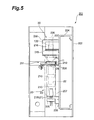
- the measuring device 201 comprises a case 202, and a lid (not illustrated) which fits onto the case 202.
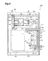
- a chassis 204 is fitted inside the case 202 in order to position an irradiation optical system 20, a detection optical system 30, and a control circuit 203 for controlling the operation of the measuring device 201 by performing various calculation processes.
- the light-emitting elements 21 (blue LED 21B or red LED 21R) are fixed to an installation plate 205, and this installation plate 205 is attached to the chassis 204 via a bracket 206.
- a mixing rod 22 is situated inside a rod case 207, in a state whereby the light input face and light output face of the mixing rod 22 contact diffusion plates 23, 24.
- the position of the mixing rod 22 in the direction of the light guide is limited by means of a restricting section 208 formed integrally with the rod case 207 confronting the diffusion plate 24, and a rod pressing plate 209 combined with the rod case 207 confronting the diffusion plate 23.
- a plurality of rod holders 210 are installed on the side face of the mixing rod 22, at prescribed intervals in the light guide direction of the mixing rod 22.
- the position of the mixing rod 22 in the direction orthogonal to the light guide direction thereof is limited by means of these rod holders 210 confronting the side walls of the rod case 207.
- test piece holder 211 constituted so that an immunochromatography test piece 10 (casing 11) can be inserted therein, is provided on the upper face of the restricting section 208 (rear side of the face confronting the diffusion plate 24).
- This test piece holder 211 functions as holding means for holding the immunochromatography test piece 10 (casing 11).
- the test piece holder 211 is constituted in such a manner that, the casing 11 makes contact with the aperture 134, when it is inserted inside the test piece holder 211 and positioned in a test piece installation section 212 formed integrally with the aperture 134.
- the test piece holder 211 is installed on the chassis 204 in a state where the restricting section 208 and test piece installation section 212 are in mutual contact.
- the insertion position of the immunochromatography test piece 10 (casing 11) in the longitudinal direction is restricted by means of a restricting section 213 formed integrally with the rod case 207 (restricting section 208) making contact with the end of the casing 11 in the longitudinal direction thereof.
- a hole section 135 for passing transmission light from the immunochromatography test piece 10 (casing 11) is provided in the aperture 134.
- the hole section 135 of the aperture 134 has a size of 5 mm ⁇ 8 mm.
- a hole section 214 for irradiating light from the diffusion plate 24 onto the immunochromatography test piece 10 (casing 11) is provided on the test piece installation section 212 of the test piece holder 211.
- the hole section 214 of the test piece installation section 212 has a size of 8 mm ⁇ 14 mm.
- the light output face of the mixing rod 22 also has a size of 8 mm ⁇ 14 mm.
- the observation window has a size of 4 mm ⁇ 8 mm.
- a mirror 215 is provided on top of the test piece holder 211.
- This mirror 215 is installed on the chassis 204 via a mirror holder 216.
- the light reflected by the mirror 215 is input to the cylindrical lens 133.
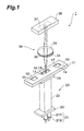
- the light path is bent in the measuring device 201 by means of this mirror 215, and as illustrated in Fig. 4, the irradiation optical system 20 and the detection optical system 30 are located in an inverse L shape.
- the control circuit 203 is installed on the chassis 204 in a position to the inner side of the irradiation optical system 20 and detection optical system 30 provided in an inverse L shape.
- the cylindrical lens 133 is positioned in such a manner that the direction of the generating line of the curved face of the cylindrical lens 133 intersects (orthogonally, for example,) with the direction of travel of the antigens (or antibodies) of the subject in the immunochromatography test piece 10, in other words, in such a manner that it faces in the direction of extension of the line-shaped pattern 18 formed by coloration in the immunochromatography test piece 10.
- a lens mask 217 forming an aperture is positioned on the light input side of the cylindrical lens 133. As shown in Fig. 8, a long rectangular slit 132 extending in the direction of the generating line of the curved face of the cylindrical lens 133 is formed in the lens mask 217. The size of this slit 132 is set to 4 mm ⁇ 8 mm.
- the cylindrical lens 133 and lens mask 217 are held on either side by a lens holder 218 and pressing ring 219, by means of the lens holder 218 and pressing ring 219 being screw fitted together.
- the lens holder 218 is fixed in a state where it is inserted into a hole section of a lens installation tube 220.
- the lens installation tube 220 with the lens holder 218 fixed thereto is installed on the chassis 204.
- the linear array CCD image sensor 236 has a light receiving face 237 extending in a one-dimensional 'direction, as illustrated in Fig. 9.
- the linear array CCD image sensor 236 is disposed in such a manner that the light receiving face 237 thereof is positioned at the point where the transmission light from the immunochromatography test piece 10 (casing 11) is formed into an image by the cylindrical lens 133.
- a plurality of light-receiving elements are disposed in a one-dimensional fashion on the light receiving face 237 of the linear array CCD image sensor 236.
- the linear array CCD image sensor 236 is fixed to a sensor holder 239 by means of a substrate 238, and this sensor holder 239 is attached to the chassis 204 via a sensor installation tube 240.
- the direction of extension of the light receiving face 237 of the linear array CCD image sensor 236 is a direction which intersects with the generating line of the curved face of the cylindrical lens 133, when the linear array CCD image sensor 236 is installed in the chassis 204.
- a baffle plate 241 for eliminating stray light is provided between the cylindrical lens 133 and the linear array CCD image sensor 236. Hole sections 242, 243 for transmitting light exiting from the cylindrical lens 133 are formed in this baffle plate 241.
- the baffle plate 241 is installed on the chassis 204.
- the detection optical system from the aperture 134 to the linear array CCD image sensor 236 is covered by a light shielding tube 250 in order to optically shield this detection optical system.
- the light shielding tube 250 is installed on the chassis 204.
- the measuring device 201 having the foregoing composition provides the same action and beneficial effects as the measuring devices 1, 101 relating to the first embodiment and the second embodiment and is able reliably to detect a line-shaped pattern 18 formed by coloration of an immunochromatography test piece 10, by means of the linear array CCD image sensor 236. Moreover, since light-emitting elements 21 (blue LED 21B or red LED 21R) are used as light sources, it is possible to prevent increase in the size of the measuring device 201.
- the measuring device 201 has a cylindrical lens 133 as an imaging lens, and this cylindrical lens 133 is disposed so that the direction of the generating line of the curved face thereof intersects with the direction of travel of the antigens or antibodies in the immunochromatography test piece 10, and it forms an image of the line-shaped pattern 18 formed in a direction intersecting with the direction of travel of the antigens or antibodies, on the linear array CCD image sensor 236, due to irradiation of measurement light.
- a lens mask 217 formed with a long rectangular slit 132 extending in the direction of the generating line of the curved face of the cylindrical lens 133 is provided at the light input face of the cylindrical lens 133, it is possible to form an image having little aberration on the linear array CCD image sensor 236.
- the measuring device 201 since a linear array CCD image sensor 236 is used as an imaging element, a measuring device 201 having an inexpensive and compact composition can be achieved. As described above, since any unevenness in coloration is optically equalized by the cylindrical lens 133, it is possible to measure the degree of coloration of the line-shaped pattern 18 formed in the immunochromatography test piece 10 with a high level of accuracy, even if a linear array CCD image sensor 236 is used as an imaging element.
- the present invention is not limited to the foregoing embodiments, and the aforementioned numerical values, and the like, can be changed appropriately.
- the transmission light of the measurement light irradiated onto the immunochromatography test piece 10 is received by a CCD image sensor 36, 236, and the light absorption of the line-shaped pattern 18 formed in the immunochromatography test piece 10 is measured on the basis of the transmission light thus received by the CCD image sensor 36, 236, but the invention is not limited to this.
- the reflected light of the measurement light irradiated onto the immunochromatography test piece 10 (casing 11) to be received by the CCD image sensor 36, 236, in such a manner that the measuring devices 1, 101, 201 measure the reflectivity of the line-shaped pattern 18 formed in the immunochromatography test piece 10 on the basis of the reflected light thus received by the CCD image sensor 36, 236.
- the present invention is applicable to a measuring device for immunochromatography test pieces used in pregnancy examinations, occult blood in faeces examinations, and the like.
Landscapes
- Health & Medical Sciences (AREA)
- Life Sciences & Earth Sciences (AREA)
- Molecular Biology (AREA)
- Physics & Mathematics (AREA)
- Chemical & Material Sciences (AREA)
- Analytical Chemistry (AREA)
- Biochemistry (AREA)
- General Health & Medical Sciences (AREA)
- General Physics & Mathematics (AREA)
- Immunology (AREA)
- Pathology (AREA)
- Investigating Or Analysing Materials By Optical Means (AREA)
- Investigating Or Analysing Materials By The Use Of Chemical Reactions (AREA)
Abstract
A measuring device 1 comprises an irradiation
optical system 20 and a detection optical system 30.
The irradiation optical system 20 comprises a light-emitting
element 21 and a mixing rod 22. The detection
optical system 30 comprises a convex lens 33 and a CCD
image sensor 36. Light from the light-emitting element
21 is diffused by a diffusing plate 23 and enters into
a mixing rod 22, where it is mixed. The light mixed
inside the mixing rod 22 is then diffused by a
diffusing plate 24 and irradiated onto an
immunochromatography test piece 10 as measurement
light. The light transmitted by the
immunochromatography test piece 10 is formed as an
image on the light receiving face 37 of a CCD image
sensor 36, by means of the convex lens 33. The CCD
image sensor 36 captures the image formed by the convex
lens 33 at the light receiving face 37.
Description
The present invention relates to a device for
measuring immunochromatography test pieces.
In immunochromatography analysis, antibodies (or
antigens) which provoke a antigen or antibody reaction
with antigens (or antibodies) in a subject (sample) are
previously coated in strips onto prescribed positions
of an immunochromatography test piece. After applying a
subject to an immunochromatography test piece, the
antigens (or antibodies) in the subject are dissolved
out using a developer solution, and are caused to
impregnate into the immunochromatography test piece,
whereupon the antigens (or antibodies) in the subject
are trapped by an antigen or antibody reaction in the
region of the antigens (or antibodies) coated onto the
immunochromatography test piece. Since the quantity
trapped is the total amount of that antigen (or
antibody) in the subject, it is possible to measure the
total amount of the antigen (or antibody) by means of
optical measurement, such as light absorption, or the
like, if the antigen (or antibody) in the subject is
previously marked by a dye. Immunochromatography
analysis can be used for measuring extremely small
quantities, compared to standard colorimetric methods.
Japanese Patent Laid-open No. H7-5110 discloses a
measuring device for measuring the concentration of a
specific material in a subject from an
immunochromatography test piece after development and
dying of the subject. In the measuring device described
in Japanese Patent Laid-open No. H7-5110, light from an
LED is irradiated onto an immunochromatography test
piece, the light reflected from the
immunochromatography test piece is detected by a CCD
color image sensor, and the degree of coloration is
identified.
However, if a light-emitting element, such as an
LED, is used as the light source of the measuring
device, then the amount of light irradiated onto the
immunochromatography test piece is low, and since the
colored region of the immunochromatography test piece
is very small (approximately 0.5 mm), it is difficult
to detect the colored region. In order to increase the
amount of light irradiated onto the
immunochromatography test piece, the use of a light-emitting
tube, such as a sodium tube, fluorescent tube,
or the like, for the light source, has been considered,
but in such cases, the device would become large in
size.
The present invention was devised with the
foregoing in view, an object thereof being to provide a
measuring device for immunochromatography test pieces
whereby detection of colored regions of an
immunochromatography test piece can be performed
reliably, without increasing the size of the device.
In order to achieve the aforementioned object, the
measuring device for immunochromatography test pieces
according to the present invention is a measuring
device for immunochromatography test pieces, comprising
an irradiation optical system for irradiating
measurement light onto immunochromatography test
pieces; and a detection optical system for detecting
light from the immunochromatography test pieces due to
irradiation of the measurement light; characterized in
that the irradiation optical system comprises a light-emitting
element, and a mixing rod for mixing the light
output from the light-emitting element, the light
exiting from the mixing rod being irradiated onto the
immunochromatography test piece as the measurement
light; and the detection optical system comprises an
imaging lens for forming an image of the light from the
immunochromatography test piece, and an imaging element
disposed in a position where the light from the
immunochromatography test piece is formed into an image
by the imaging lens, the light transmitted by the
immunochromatography test piece being detected by the
imaging element.
Thus, an irradiation optical system and a
detection optical system are provided, the irradiation
optical system comprising a light-emitting element, and
a mixing rod for mixing the light output from the
light-emitting element, the light exiting from the
mixing rod being irradiated onto the
immunochromatography test piece as the measurement
light; and the detection optical system comprising an
imaging lens for forming an image of the light from the
immunochromatography test piece, and an imaging element
disposed in a position where the light from the
immunochromatography test piece is formed into an image
by the imaging lens, the light from the
immunochromatography test piece being received and
detected by the imaging element. Since the light output
by the light-emitting element is mixed by the mixing
rod and then irradiated onto the immunochromatography
test piece, attenuation of light by the light-emitting
element is suppressed, and the amount of light
irradiated onto the immunochromatography test piece is
increased. Consequently, the colored portion of the
immunochromatography test piece can be detected
reliably by the imaging element. Moreover, since a
light-emitting element is used as a light source, it is
possible to suppress increase in the size of the
device.
The measuring device for immunochromatography test
pieces according to the present invention may also be
characterized in that diffusing means for diffusing the
light input to the mixing rod and the light exiting
from the mixing rod are further provided on the light
input side and light output side of the mixing rod.
By further providing diffusing means for diffusing
the light input to the mixing rod and the light exiting
from the mixing rod on the light input side and light
output side of the mixing rod, the light irradiated
onto the immunochromatography test pieces is
approximately equalized. Thereby, the colored region of
the immunochromatography test pieces can be detected
with even greater reliability by the imaging element.
Furthermore, the measuring device for
immunochromatography test pieces according to the
present invention may also be characterized in that the
immunochromatography test piece is held in a casing
having an observation window; the irradiation optical
system irradiating the light emitted from the mixing
rod towards the observation window, as the measurement
light; and the surface area of the light output face of
the mixing rod being set to a larger area than the
surface area of the observation window.
The immunochromatography test piece is held in a
casing having an observation window and the irradiation
optical system irradiates the light emitted from the
mixing rod as measurement light onto the observation
window, and since the surface area of the light output
face of the mixing rod is greater than the surface area
of the observation window, the light irradiated onto
the position corresponding to the observation window of
the immunochromatography test piece is approximately
equalized. Thereby, the colored region of the
immunochromatography test piece can be detected with
even greater reliability by the imaging element.
A measuring device for immunochromatography test
pieces relating to embodiments of the present invention
is now described with reference to the drawings. In the
respective drawings, similar elements or elements
having similar functions are similarly labelled, and
duplicated description thereof is omitted.
Firstly, a measuring device 1 for
immunochromatography test pieces relating to a first
embodiment is described.
The measuring device 1 comprises an irradiating
optical system 20 for irradiating measurement light
onto an immunochromatography test piece 10, and a
detection optical system 30 for detecting light from an
immunochromatography test piece 10 by irradiation of
the measurement light. The irradiation optical system
20 comprises a light-emitting element 21 and a mixing
rod 22. Moreover, the detection optical system 30
comprises an aperture 31, a convex lens 33 forming an
imaging lens, and a CCD image sensor 36 forming an
imaging element.
The immunochromatography test piece 10 has a long
rectangular shape and is made from a material such as a
nitrocellulose membrane, or filter paper, or the like.
This immunochromatography test piece 10 is held inside
a casing having a long rectangular shape in plan view,
and a subject application window 12, observation window
13 and control window 14 are provided extending in the
direction of the longer side in the casing 11. The
immunochromatography test piece 10 comprises a subject
application section 15 provided in a position
corresponding to the subject application window 12, and
detecting sections 16, 17 provided in positions
corresponding to the observation window 13 and control
window 14. The detecting section 16 has a line shape
(or band shape) formed by coating respective antigens
(or antibodies) which react with antigens (or
antibodies) in the subject, and causing same to
solidify. The casing 11 which holds the
immunochromatography test piece 10 is held by holding
means (not illustrated). The observation window 13 has
a size of 4 mm × 8 mm, for example.
The subject is applied dropwise via the subject
application window 12 onto the subject application
section 15 of the immunochromatography test piece 10.
The antigens (or antibodies) in the subject couple with
the indicator dye and the indicator dye coupled with
the antigens (or antibodies) in the subject, as well as
unreacted indicator dye, travel in the longitudinal
direction of the immunochromatography test piece 10.
Supposing that the subject contains antigens, then it
is assumed that the antigens will undergo an
antigen/antibody reaction with the respective detecting
sections. As the subject travels, the antigens in the
subject and the antigens fixed to the detecting section
16 react specifically and a line-shaped pattern 18
colored by the indicator dye is formed in the detecting
section 16 which has reacted. This colored line-shaped
pattern 18 is formed extending in a direction
intersecting (for example, orthogonally) with the
direction of travel of the antigens (or antibodies) of
the subject in the immunochromatography test piece 10,
and it can be observed by means of the observation
window 13.
The light-emitting element 21 comprises a plurality
of LEDs having different light emission wavelengths, in
the present embodiment, a blue LED 21B and a red LED
21R. If the line-shaped pattern 18 formed by the
antigen/antibody reaction is colored red, then the blue
LED 21B is caused to emit light. If the line-shaped
pattern 18 formed by the antigen/antibody reaction is
colored blue, then the red LED 21R is caused to emit
light.
The mixing rod 22 is a square-shaped (or circular-shaped)
rod made from transparent acrylic resin for
mixing the light output by the light-emitting element
21 (blue LED 21B or red LED 21R), and it has a light
input face and a light output face at the respective
ends thereof. The aforementioned light-emitting element
21 is positioned on the light input face side of the
mixing rod 22. An immunochromatography test piece 10
(casing 11) is positioned on the light output face side
of the mixing rod 22. More specifically, the
immunochromatography test piece 10 (casing 11) is
positioned opposing the light output face of the mixing
rod 22 in such a manner that the observation window 13
of the casing 11 coincides with the light output face
of the mixing rod 22. The light output face of the
mixing rod 22 has a size of 8 mm x 14 mm, and the
surface area of the light output face of this mixing
rod 22 is set to a larger area than the surface area of
the opening in the observation window 13 of the casing
11.
The light output from the light-emitting element 21
(blue LED 21B or red LED 21R) is diffused by the
diffusing plate 23 and then enters into the mixing rod
22 via the light input face of the mixing rod 22. The
light that has entered the mixing rod 22 is mixed by
being fully reflected at the side faces of the mixing
rod 22 whilst it is propagated therein, and this mixed
light arrives at the light output face of the mixing
rod 22. The light arriving at the light output face of
the mixing rod 22 is diffused by the diffusing plate
24, and is then irradiated as measurement light from
the rear face of the observation window 13 of the
casing 11 in the direction of the immunochromatography
test piece 10 (observation window 13 of the casing 11).
The aperture 31 has a restricting hole section 32.
The transmission light that is transmitted through the
immunochromatography test piece 10 (casing 11) due to
irradiation of measurement light and exits from the
observation window 13 is restricted by the restricting
hole section 32 of the aperture 31. The convex lens 33
forms an image of the transmission light from the
immunochromatography test piece 10 (casing 11) which is
incident thereon via the restricting hole section 32 of
the aperture 31.
The CCD image sensor 36 has a light receiving face
37, which is situated at the position where an image of
the transmission light from the immunochromatography
test piece 10 (casing 11) is formed by the convex lens
33. Light-receiving elements are provided in a one-dimensional
or two-dimensional array on the light-receiving
face 37. The CCD image sensor 36 detects the
transmission light from the immunochromatography test
piece 10 by capturing the image formed by the convex
lens 33 on the light receiving face 37.
Next, a method for determining the concentration of
the subject is described. When transmission light from
the immunochromatography test piece 10 is detected by
the CCD image sensor 36, the light absorption of the
line-shaped pattern 18 formed by coloration is
determined as described below, on the basis of the
output signal from the CCD image sensor 36. Firstly, a
light absorption profile of the transmission light of
the immunochromatography test piece 10 is created as
illustrated in Fig. 2, on the basis of the output
signal intensity from the CCD image sensor 36 and the
position of the light-receiving element (channel) of
the CCD image sensor 36. Thereupon, the light
absorption ABS is calculated by means of the following
equation (1), taking To as the output signal intensity
at a position in the created absorption profile
corresponding to a portion of the immunochromatography
test piece 10 that is not colored, and taking Ti as the
output light intensity at a position corresponding to a
colored region thereof (line-shaped pattern 18).
ABS = log (To /Ti )
When the light absorption ABS is calculated, the
total quantity (concentration) of antibodies or
antigens contained in the subjected is derived from the
light absorption ABS, by referring to a previously
created quantity characteristics graph.
It is also possible to calculate the light
absorption ABS on the basis of the following equation
(2), taking Tao as the average output signal intensity
at a position of the created absorption profile
corresponding to a region of the immunochromatography
test piece that is not colored, and Tai as the average
output signal intensity at a position corresponding to
a color region (line-shaped pattern).
ABS = log (Tao /Tai )
In this way, an irradiation optical system 20 and a
detection optical system 30 are provided in the
measuring device 1. The irradiation optical system 20
comprises a light-emitting element 21 (blue LED 21B or
red LED 21R), and a mixing rod 22, and the light
emitted from the mixing rod 22 is irradiated as
measurement light onto the immunochromatography test
piece 10 (casing 11). The detection optical system 30
comprises a convex lens 33 and CCD image sensor 36, and
detects transmission light from the
immunochromatography test piece 10 (casing 11) by means
of the CCD image sensor 36. Since the light output by
the light-emitting elements 21 is mixed by the mixing
rod 22 before being irradiated onto the
immunochromatography test piece 10 (casing 11),
attenuation of the light from the light-emitting
elements 21 is suppressed, and the amount of light
irradiated onto the immunochromatography test piece 10
is increased. Consequently, the CCD image sensor 36 is
able reliably to detect a line-shaped pattern 18 formed
by coloration of the immunochromatography test piece
10. Moreover, since light-emitting elements 21 (a blue
LED 21B and a red LED 21R) are used, it is possible to
suppress increase in the size of the measuring device
1.
Furthermore, in the measuring device 1, since
diffusing plates 23, 24 are provided at the light input
face and light output face of the mixing rod 22, the
light irradiated onto the immunochromatography test
piece 10 (casing 11) is approximately equalized.
Thereby, it is possible to perform detection of the
line-shaped pattern 18 in the immunochromatography test
piece 10 by means of the CCD image sensor 36 with even
greater reliability.
Furthermore, in the measuring device 1, since the
surface area of the light output face of the mixing rod
22 is greater than the surface area of the observation
window 13 of the casing 11, the light irradiated onto a
position corresponding to the observation window 13 of
the immunochromatography test piece 10 will be further
equalized. Thereby, the detection of the line-shaped
pattern 18 in the immunochromatography test piece 10 by
means of the CCD image sensor 36 can be performed with
even greater reliability.
Moreover, the irradiation optical system 20 and
detection optical system 30 in the measuring device 1
are positioned in such a manner that the CCD image
sensor 36 receives the transmission light of the
measurement light irradiated onto the
immunochromatography test piece 10, and the light
absorption of the line-shaped pattern 18 formed by
coloration is measured on the basis of the transmission
light received by the CCD image sensor 36. Thereby, the
degree of coloration of the line-shaped pattern 18
formed in the immunochromatography test piece 10 can be
measured simply and very accurately, and the total
amount (concentration) of antigens or antibodies
contained in the subject can be measured precisely.
Next, with reference to Fig. 3, the measuring
device 101 for immunochromatography test pieces
relating to a second embodiment of the present
invention is described. The measuring device 101
relating to the second embodiment differs from the
measuring device 1 relating to the first embodiment in
that the imaging lens is a cylindrical lens.
The measuring device 101 comprises an aperture 131,
and a cylindrical lens 133 forming an imaging lens.
This cylindrical lens 133 is disposed in such a manner
that the direction of the generating line of the curved
face of the cylindrical lens 133 intersects
(orthogonally, for example) with the direction of
travel of the antigens (or antibodies) of the subject
in the immunochromatography test piece 10, in other
words, in such a manner that it faces the direction of
extension of the line-shaped pattern 18 formed by
coloration of the immunochromatography test piece 10.
The aperture 131 is disposed on the light input
face side of the cylindrical lens 133. A long
rectangular slit 132 extending in the direction of the
generating line of the curved face of the cylindrical
lens 133 is formed in this aperture 131.
An aperture 134 for restricting the input of light
other than light from the observation window 13 to the
cylindrical lens 133 is provided on the light output
side of the immunochromatography test piece 10 (casing
11). A hole section 135 for passing transmission light
from the immunochromatography test piece 10 (casing 11)
is provided in the aperture 134.
The measuring device 101 having the foregoing
composition provides the same action and beneficial
effects as the measuring device 1 relating to the first
embodiment and is able reliably to detect a line-shaped
pattern 18 formed by coloration of an
immunochromatography test piece 10, by means of the CCD
image sensor 36. Moreover, since light-emitting
elements 21 (blue LED 21B or red LED 21R) are used as
light sources, it is possible to prevent increase in
the size of the measuring device 101.
Moreover, the measuring device 101 has a
cylindrical lens 133 as an imaging lens, and this
cylindrical lens 133 is disposed so that the direction
of the generating line of the curved face thereof
intersects with the direction of travel of the antigens
or antibodies in the immunochromatography test piece
10, and it forms an image of the line-shaped pattern 18
formed in a direction intersecting with the direction
of travel of the antigens or antibodies, on the CCD
image sensor 36, due to irradiation of measurement
light. Thereby, light that is parallel to the direction
of travel of the antigens or antibodies in the
immunochromatography test piece 10 is formed as an
image on the CCD image sensor 36, and light that is
orthogonal to the direction of travel of the antigens
or antibodies in the immunochromatography test piece 10
is defocused and equalized. Consequently, even if
uneven coloration occurs in the direction of extension
of the line-shaped pattern 18 formed by coloration of
the immunochromatography test piece 10, this uneven
coloration will be optically equalized by the
cylindrical lens 133, and hence a pattern wherein
uneven coloration is optically equalized will be formed
as an image on the CCD image sensor 36. As a result, it
is possible to measure the degree of coloration of the
line-shaped pattern 18 formed on the
immunochromatography test piece 10 to a high level of
accuracy.
Moreover, since an aperture 131 formed with a long
rectangular slit 132 extending in the direction of the
generating line of the curved face of the cylindrical
lens 133 is disposed on the light input face side of
the cylindrical lens 133, it is possible to form an
image having little aberration on at the CCD image
sensor 36.
Next, a measuring device 201 for
immunochromatography test pieces relating to a third
embodiment is described on the basis of Fig. 4 to Fig.
9. The measuring device 201 relating to the third
embodiment differs from the measuring device 101
relating to the second embodiment and second embodiment
in that the light path is constituted in a bent fashion
by using mirrors.
As shown in Fig. 4 and Fig. 5, the measuring device
201 comprises a case 202, and a lid (not illustrated)
which fits onto the case 202. A chassis 204 is fitted
inside the case 202 in order to position an irradiation
optical system 20, a detection optical system 30, and a
control circuit 203 for controlling the operation of
the measuring device 201 by performing various
calculation processes.
The light-emitting elements 21 (blue LED 21B or red
LED 21R) are fixed to an installation plate 205, and
this installation plate 205 is attached to the chassis
204 via a bracket 206.
A mixing rod 22 is situated inside a rod case 207,
in a state whereby the light input face and light
output face of the mixing rod 22 contact diffusion
plates 23, 24. The position of the mixing rod 22 in the
direction of the light guide is limited by means of a
restricting section 208 formed integrally with the rod
case 207 confronting the diffusion plate 24, and a rod
pressing plate 209 combined with the rod case 207
confronting the diffusion plate 23. A plurality of rod
holders 210 are installed on the side face of the
mixing rod 22, at prescribed intervals in the light
guide direction of the mixing rod 22. The position of
the mixing rod 22 in the direction orthogonal to the
light guide direction thereof is limited by means of
these rod holders 210 confronting the side walls of the
rod case 207.
A test piece holder 211 constituted so that an
immunochromatography test piece 10 (casing 11) can be
inserted therein, is provided on the upper face of the
restricting section 208 (rear side of the face
confronting the diffusion plate 24). This test piece
holder 211 functions as holding means for holding the
immunochromatography test piece 10 (casing 11).
The test piece holder 211 is constituted in such a
manner that, the casing 11 makes contact with the
aperture 134, when it is inserted inside the test piece
holder 211 and positioned in a test piece installation
section 212 formed integrally with the aperture 134.
The test piece holder 211 is installed on the chassis
204 in a state where the restricting section 208 and
test piece installation section 212 are in mutual
contact. The insertion position of the
immunochromatography test piece 10 (casing 11) in the
longitudinal direction is restricted by means of a
restricting section 213 formed integrally with the rod
case 207 (restricting section 208) making contact with
the end of the casing 11 in the longitudinal direction
thereof.
As shown in Fig. 6, a hole section 135 for passing
transmission light from the immunochromatography test
piece 10 (casing 11) is provided in the aperture 134.
The hole section 135 of the aperture 134 has a size of
5 mm × 8 mm. Furthermore, as shown in Fig. 7, a hole
section 214 for irradiating light from the diffusion
plate 24 onto the immunochromatography test piece 10
(casing 11) is provided on the test piece installation
section 212 of the test piece holder 211. The hole
section 214 of the test piece installation section 212
has a size of 8 mm × 14 mm. The light output face of the
mixing rod 22 also has a size of 8 mm × 14 mm. The
observation window has a size of 4 mm × 8 mm.
A mirror 215 is provided on top of the test piece
holder 211. This mirror 215 is installed on the chassis
204 via a mirror holder 216. The light reflected by the
mirror 215 is input to the cylindrical lens 133. The
light path is bent in the measuring device 201 by means
of this mirror 215, and as illustrated in Fig. 4, the
irradiation optical system 20 and the detection optical
system 30 are located in an inverse L shape. The
control circuit 203 is installed on the chassis 204 in
a position to the inner side of the irradiation optical
system 20 and detection optical system 30 provided in
an inverse L shape. By laying out the irradiation
optical system 20, detection optical system 30 and
control circuit 203 in this way, it is possible to
achieve compactification of the measuring device 201.
The cylindrical lens 133 is positioned in such a
manner that the direction of the generating line of the
curved face of the cylindrical lens 133 intersects
(orthogonally, for example,) with the direction of
travel of the antigens (or antibodies) of the subject
in the immunochromatography test piece 10, in other
words, in such a manner that it faces in the direction
of extension of the line-shaped pattern 18 formed by
coloration in the immunochromatography test piece 10. A
lens mask 217 forming an aperture is positioned on the
light input side of the cylindrical lens 133. As shown
in Fig. 8, a long rectangular slit 132 extending in the
direction of the generating line of the curved face of
the cylindrical lens 133 is formed in the lens mask
217. The size of this slit 132 is set to 4 mm × 8 mm.
The cylindrical lens 133 and lens mask 217 are held
on either side by a lens holder 218 and pressing ring
219, by means of the lens holder 218 and pressing ring
219 being screw fitted together. The lens holder 218 is
fixed in a state where it is inserted into a hole
section of a lens installation tube 220. The lens
installation tube 220 with the lens holder 218 fixed
thereto is installed on the chassis 204.
Light exiting the cylindrical lens 133 is incident
on a linear array CCD image sensor 236. The linear
array CCD image sensor 236 has a light receiving face
237 extending in a one-dimensional 'direction, as
illustrated in Fig. 9. The linear array CCD image
sensor 236 is disposed in such a manner that the light
receiving face 237 thereof is positioned at the point
where the transmission light from the
immunochromatography test piece 10 (casing 11) is
formed into an image by the cylindrical lens 133. A
plurality of light-receiving elements (in the present
embodiment, 2048 elements) are disposed in a one-dimensional
fashion on the light receiving face 237 of
the linear array CCD image sensor 236. The linear array
CCD image sensor 236 is fixed to a sensor holder 239 by
means of a substrate 238, and this sensor holder 239 is
attached to the chassis 204 via a sensor installation
tube 240. As shown in Fig. 4, the direction of
extension of the light receiving face 237 of the linear
array CCD image sensor 236 is a direction which
intersects with the generating line of the curved face
of the cylindrical lens 133, when the linear array CCD
image sensor 236 is installed in the chassis 204.
A baffle plate 241 for eliminating stray light is
provided between the cylindrical lens 133 and the
linear array CCD image sensor 236. Hole sections 242,
243 for transmitting light exiting from the cylindrical
lens 133 are formed in this baffle plate 241. The
baffle plate 241 is installed on the chassis 204.
The detection optical system from the aperture 134
to the linear array CCD image sensor 236 is covered by
a light shielding tube 250 in order to optically shield
this detection optical system. The light shielding tube
250 is installed on the chassis 204.
The measuring device 201 having the foregoing
composition provides the same action and beneficial
effects as the measuring devices 1, 101 relating to the
first embodiment and the second embodiment and is able
reliably to detect a line-shaped pattern 18 formed by
coloration of an immunochromatography test piece 10, by
means of the linear array CCD image sensor 236.
Moreover, since light-emitting elements 21 (blue LED
21B or red LED 21R) are used as light sources, it is
possible to prevent increase in the size of the
measuring device 201.
Furthermore, the measuring device 201 has a
cylindrical lens 133 as an imaging lens, and this
cylindrical lens 133 is disposed so that the direction
of the generating line of the curved face thereof
intersects with the direction of travel of the antigens
or antibodies in the immunochromatography test piece
10, and it forms an image of the line-shaped pattern 18
formed in a direction intersecting with the direction
of travel of the antigens or antibodies, on the linear
array CCD image sensor 236, due to irradiation of
measurement light. Thereby, light that is parallel to
the direction of travel of the antigens or antibodies
in the immunochromatography test piece 10 is formed as
an image on the linear array CCD image sensor 236, and
light that is orthogonal to the direction of travel of
the antigens or antibodies in the immunochromatography
test piece 10 is defocused and equalized. Consequently,
even if uneven coloration occurs in the direction of
extension of the line-shaped pattern 18 formed by
coloration of the immunochromatography test piece 10,
this uneven coloration will be optically equalized by
the cylindrical lens 133, and hence a pattern wherein
uneven coloration is optically equalized will be formed
as an image on the linear array CCD image sensor 236.
As a result, it is possible to measure the degree of
coloration of the line-shaped pattern 18 formed on the
immunochromatography test piece 10 to a high level of
accuracy.
Moreover, in the measuring device 201, since a lens
mask 217 formed with a long rectangular slit 132
extending in the direction of the generating line of
the curved face of the cylindrical lens 133 is provided
at the light input face of the cylindrical lens 133, it
is possible to form an image having little aberration
on the linear array CCD image sensor 236.
Moreover, in the measuring device 201, since a
linear array CCD image sensor 236 is used as an imaging
element, a measuring device 201 having an inexpensive
and compact composition can be achieved. As described
above, since any unevenness in coloration is optically
equalized by the cylindrical lens 133, it is possible
to measure the degree of coloration of the line-shaped
pattern 18 formed in the immunochromatography test
piece 10 with a high level of accuracy, even if a
linear array CCD image sensor 236 is used as an imaging
element.
The present invention is not limited to the
foregoing embodiments, and the aforementioned numerical
values, and the like, can be changed appropriately.
Moreover, in the measuring devices 1, 101, 201
relating to the first embodiment to third embodiment
described above, the transmission light of the
measurement light irradiated onto the
immunochromatography test piece 10 (casing 11) is
received by a CCD image sensor 36, 236, and the light
absorption of the line-shaped pattern 18 formed in the
immunochromatography test piece 10 is measured on the
basis of the transmission light thus received by the
CCD image sensor 36, 236, but the invention is not
limited to this. For example, it is also possible for
the reflected light of the measurement light irradiated
onto the immunochromatography test piece 10 (casing 11)
to be received by the CCD image sensor 36, 236, in such
a manner that the measuring devices 1, 101, 201 measure
the reflectivity of the line-shaped pattern 18 formed
in the immunochromatography test piece 10 on the basis
of the reflected light thus received by the CCD image
sensor 36, 236.
The present invention is applicable to a measuring
device for immunochromatography test pieces used in
pregnancy examinations, occult blood in faeces
examinations, and the like.
Claims (3)
- A measuring device for immunochromatography test pieces, comprising an irradiation optical system for irradiating measurement light onto immunochromatography test pieces, and a detection optical system for detecting light from said immunochromatography test pieces as a result of irradiation of said measurement light;
characterized in that said irradiation optical system comprises a light-emitting element, and a mixing rod for mixing the light output from said light-emitting element, and irradiates the light exiting from said mixing rod onto said immunochromatography test piece as said measurement light; and
said detection optical system comprises an imaging lens for forming an image of said light from said immunochromatography test piece, and an imaging element disposed in a position where said light from said immunochromatography test piece is formed into an image by said imaging lens, and detects the light transmitted by said immunochromatography test piece by means of said imaging element. - The measuring device for immunochromatography test pieces according to claim 1, characterized in that diffusing means for diffusing the light input to said mixing rod and the light exiting from said mixing rod are further provided on the light input face side and light output face side of said mixing rod.
- The measuring device for immunochromatography test pieces according to claim 1,
characterized in that said immunochromatography test piece is held in a casing having an observation window;
said irradiation optical system irradiates said light emitted from said mixing rod towards said observation window, as said measurement light; and
the surface area of the light output face of said mixing rod is set to a larger area than the surface area of said observation window.
Applications Claiming Priority (3)
| Application Number | Priority Date | Filing Date | Title |
|---|---|---|---|
| JP2000111137A JP4188537B2 (en) | 2000-04-12 | 2000-04-12 | Immunochromatographic test piece measuring device |
| JP2000111137 | 2000-04-12 | ||
| PCT/JP2001/002991 WO2001077680A1 (en) | 2000-04-12 | 2001-04-06 | Measuring method for immunochromatographic test strip |
Publications (2)
| Publication Number | Publication Date |
|---|---|
| EP1273916A1 true EP1273916A1 (en) | 2003-01-08 |
| EP1273916A4 EP1273916A4 (en) | 2004-09-29 |
Family
ID=18623528
Family Applications (1)
| Application Number | Title | Priority Date | Filing Date |
|---|---|---|---|
| EP01917845A Withdrawn EP1273916A4 (en) | 2000-04-12 | 2001-04-06 | Measuring method for immunochromatographic test strip |
Country Status (5)
| Country | Link |
|---|---|
| US (1) | US6879399B2 (en) |
| EP (1) | EP1273916A4 (en) |
| JP (1) | JP4188537B2 (en) |
| AU (1) | AU2001244735A1 (en) |
| WO (1) | WO2001077680A1 (en) |
Cited By (2)
| Publication number | Priority date | Publication date | Assignee | Title |
|---|---|---|---|---|
| CN102692498A (en) * | 2012-06-11 | 2012-09-26 | 华中农业大学 | Automatic code reading device and automatic code reading method of sulfanilamide type medicine residue detecting reagent strip |
| CN104246477A (en) * | 2012-03-28 | 2014-12-24 | 横河电机株式会社 | Substance properties measuring device |
Families Citing this family (14)
| Publication number | Priority date | Publication date | Assignee | Title |
|---|---|---|---|---|
| US7154592B2 (en) * | 2003-02-11 | 2006-12-26 | Bayer Healthcare Llc. | Multiwavelength readhead for use in the determination of analytes in body fluids |
| GB2402475A (en) * | 2003-06-04 | 2004-12-08 | Inverness Medical Switzerland | Analyte assay reading providing prompt result declaration |
| US8273579B2 (en) * | 2004-06-08 | 2012-09-25 | Bizpac (Australia) Pty. Ltd. | Method and apparatus for inspecting biological samples |
| US8789756B2 (en) * | 2006-02-25 | 2014-07-29 | Roche Diagnostics Operations, Inc. | Test element coding apparatuses, systems and methods |
| JP2008281394A (en) * | 2007-05-09 | 2008-11-20 | Olympus Corp | Automatic analyzer |
| AU2010236424B2 (en) * | 2009-04-15 | 2016-03-10 | Relia Biotechnologies (Shenzhen) Ltd. | Diagnostic devices and related methods |
| JP4742166B2 (en) * | 2009-12-04 | 2011-08-10 | 株式会社日立ハイテクノロジーズ | Sample analyzer |
| JP5603114B2 (en) * | 2010-03-19 | 2014-10-08 | 古河電気工業株式会社 | Reader and diagnostic system |
| JP5695935B2 (en) * | 2011-02-24 | 2015-04-08 | 横河電機株式会社 | Infrared analyzer |
| WO2013096994A1 (en) * | 2011-12-30 | 2013-07-04 | Burbidge Pty Ltd | Media absorbency determination |
| JP6139565B2 (en) * | 2012-02-06 | 2017-05-31 | ザ リージェンツ オブ ザ ユニバーシティ オブ カリフォルニアThe Regents Of The University Of California | Portable rapid diagnostic test reader |
| ES2776481T3 (en) * | 2012-10-01 | 2020-07-30 | Hoffmann La Roche | Light source module and procedure for modifying an analytical instrument to analyze a sample |
| US10267679B2 (en) | 2014-07-23 | 2019-04-23 | Ascensia Diabetes Care Holdings Ag | Light switching indicators by wavelength filtration for a testing device |
| WO2020165488A1 (en) | 2019-02-13 | 2020-08-20 | Labrox Oy | A test strip reader device and a method for detecting a test result |
Family Cites Families (12)
| Publication number | Priority date | Publication date | Assignee | Title |
|---|---|---|---|---|
| JPS4818273B1 (en) * | 1968-02-24 | 1973-06-05 | ||
| JPH0629847B2 (en) | 1985-05-16 | 1994-04-20 | 株式会社島津製作所 | Chromatoskiana |
| JP2683248B2 (en) * | 1988-06-13 | 1997-11-26 | 大日本印刷株式会社 | Inspection method of colored periodic pattern |
| US5031078A (en) * | 1989-08-28 | 1991-07-09 | Vari-Lite, Inc. | Additive color mixing system with variable hue and saturation light sources |
| JP3559975B2 (en) | 1992-09-10 | 2004-09-02 | テラメックス株式会社 | Analysis method using test pieces |
| JPH06250137A (en) | 1993-02-23 | 1994-09-09 | Casio Comput Co Ltd | Method and device for inspecting appearance |
| US5770389A (en) * | 1993-09-27 | 1998-06-23 | Abbott Laboratories | Apparatus and method for determining the quanity of an analyte in a biological sample by means of transmission photometry |
| ATE224053T1 (en) * | 1993-11-12 | 2002-09-15 | Inverness Medical Switzerland | DEVICE FOR READING TEST STRIPS |
| EP0658811B1 (en) * | 1993-12-13 | 1998-06-17 | Carl Zeiss | Illumination device for a microlithographic projection exposure apparatus |
| JP3541232B2 (en) | 1995-06-05 | 2004-07-07 | テラメックス株式会社 | Method for measuring the degree of coloration of immunochromatographic test strips |
| JPH1184529A (en) | 1997-09-09 | 1999-03-26 | Mitsubishi Electric Corp | Projector device |
| JP2000121562A (en) | 1998-10-15 | 2000-04-28 | Ebisu Denki Kk | Colored material quantification device and storage medium for colorized material quantification |
-
2000
- 2000-04-12 JP JP2000111137A patent/JP4188537B2/en not_active Expired - Fee Related
-
2001
- 2001-04-06 US US10/257,270 patent/US6879399B2/en not_active Expired - Fee Related
- 2001-04-06 AU AU2001244735A patent/AU2001244735A1/en not_active Abandoned
- 2001-04-06 EP EP01917845A patent/EP1273916A4/en not_active Withdrawn
- 2001-04-06 WO PCT/JP2001/002991 patent/WO2001077680A1/en not_active Ceased
Cited By (4)
| Publication number | Priority date | Publication date | Assignee | Title |
|---|---|---|---|---|
| CN104246477A (en) * | 2012-03-28 | 2014-12-24 | 横河电机株式会社 | Substance properties measuring device |
| CN104246477B (en) * | 2012-03-28 | 2017-04-12 | 横河电机株式会社 | Substance properties measuring device |
| CN102692498A (en) * | 2012-06-11 | 2012-09-26 | 华中农业大学 | Automatic code reading device and automatic code reading method of sulfanilamide type medicine residue detecting reagent strip |
| CN102692498B (en) * | 2012-06-11 | 2014-11-12 | 华中农业大学 | Automatic code reading device and automatic code reading method of sulfanilamide type medicine residue detecting reagent strip |
Also Published As
| Publication number | Publication date |
|---|---|
| US6879399B2 (en) | 2005-04-12 |
| US20030160958A1 (en) | 2003-08-28 |
| JP2001296245A (en) | 2001-10-26 |
| EP1273916A4 (en) | 2004-09-29 |
| AU2001244735A1 (en) | 2001-10-23 |
| JP4188537B2 (en) | 2008-11-26 |
| WO2001077680A1 (en) | 2001-10-18 |
Similar Documents
| Publication | Publication Date | Title |
|---|---|---|
| US6819422B2 (en) | Measuring method for immunochromatographic test strip | |
| US6879399B2 (en) | Measuring method for immunochromatographic test strip | |
| JP3655588B2 (en) | Test element analysis system | |
| EP1249696A1 (en) | Device for chromatographic quantitative measurement | |
| EP0864089B1 (en) | Optical apparatus for performing an immunoassay | |
| CN100487424C (en) | Measuring device for immunochromatography test piece | |
| US12000785B2 (en) | Apparatus and method for detecting photoluminescent light emitted from a sample | |
| WO2018229477A1 (en) | Reading device for a lateral flow test strip | |
| JP2002022743A (en) | Immunochromatographic test utensil and immunochromatographic test strip measuring device | |
| JP2002267664A (en) | Immunochromatographic test strip measurement device | |
| JPS61502418A (en) | Optical analysis method and device | |
| JP4128730B2 (en) | Immunochromatographic test piece measuring device | |
| JP2007225400A (en) | Optical detector | |
| KR20230137907A (en) | Survey optical systems, survey devices, and optical measurement devices | |
| JP2011089917A (en) | Testpiece housing and immunochromatographic device for concentration measurement | |
| JP2533845B2 (en) | Immunological analysis method | |
| JPH02156139A (en) | Light source apparatus for measuring concentration |
Legal Events
| Date | Code | Title | Description |
|---|---|---|---|
| PUAI | Public reference made under article 153(3) epc to a published international application that has entered the european phase |
Free format text: ORIGINAL CODE: 0009012 |
|
| 17P | Request for examination filed |
Effective date: 20021105 |
|
| AK | Designated contracting states |
Kind code of ref document: A1 Designated state(s): AT BE CH CY DE DK ES FI FR GB GR IE IT LI LU MC NL PT SE TR |
|
| AX | Request for extension of the european patent |
Free format text: AL;LT;LV;MK;RO;SI |
|
| RBV | Designated contracting states (corrected) |
Designated state(s): CH DE FR GB LI |
|
| A4 | Supplementary search report drawn up and despatched |
Effective date: 20040812 |
|
| STAA | Information on the status of an ep patent application or granted ep patent |
Free format text: STATUS: THE APPLICATION IS DEEMED TO BE WITHDRAWN |
|
| 18D | Application deemed to be withdrawn |
Effective date: 20060801 |