EP1273553B1 - Verfahren zum Betrieb eines Apparats zur Erzeugung von Wasserstoff und Apparate zur Durchführung der Verfahren - Google Patents
Verfahren zum Betrieb eines Apparats zur Erzeugung von Wasserstoff und Apparate zur Durchführung der Verfahren Download PDFInfo
- Publication number
- EP1273553B1 EP1273553B1 EP20020014781 EP02014781A EP1273553B1 EP 1273553 B1 EP1273553 B1 EP 1273553B1 EP 20020014781 EP20020014781 EP 20020014781 EP 02014781 A EP02014781 A EP 02014781A EP 1273553 B1 EP1273553 B1 EP 1273553B1
- Authority
- EP
- European Patent Office
- Prior art keywords
- reformer
- catalyst stage
- fed
- air
- hydrogen
- Prior art date
- Legal status (The legal status is an assumption and is not a legal conclusion. Google has not performed a legal analysis and makes no representation as to the accuracy of the status listed.)
- Expired - Lifetime
Links
Images

Classifications
-
- B—PERFORMING OPERATIONS; TRANSPORTING
- B01—PHYSICAL OR CHEMICAL PROCESSES OR APPARATUS IN GENERAL
- B01J—CHEMICAL OR PHYSICAL PROCESSES, e.g. CATALYSIS OR COLLOID CHEMISTRY; THEIR RELEVANT APPARATUS
- B01J8/00—Chemical or physical processes in general, conducted in the presence of fluids and solid particles; Apparatus for such processes
- B01J8/02—Chemical or physical processes in general, conducted in the presence of fluids and solid particles; Apparatus for such processes with stationary particles, e.g. in fixed beds
- B01J8/04—Chemical or physical processes in general, conducted in the presence of fluids and solid particles; Apparatus for such processes with stationary particles, e.g. in fixed beds the fluid passing successively through two or more beds
- B01J8/0446—Chemical or physical processes in general, conducted in the presence of fluids and solid particles; Apparatus for such processes with stationary particles, e.g. in fixed beds the fluid passing successively through two or more beds the flow within the beds being predominantly vertical
- B01J8/0476—Chemical or physical processes in general, conducted in the presence of fluids and solid particles; Apparatus for such processes with stationary particles, e.g. in fixed beds the fluid passing successively through two or more beds the flow within the beds being predominantly vertical in two or more otherwise shaped beds
- B01J8/048—Chemical or physical processes in general, conducted in the presence of fluids and solid particles; Apparatus for such processes with stationary particles, e.g. in fixed beds the fluid passing successively through two or more beds the flow within the beds being predominantly vertical in two or more otherwise shaped beds the beds being superimposed one above the other
-
- B—PERFORMING OPERATIONS; TRANSPORTING
- B01—PHYSICAL OR CHEMICAL PROCESSES OR APPARATUS IN GENERAL
- B01J—CHEMICAL OR PHYSICAL PROCESSES, e.g. CATALYSIS OR COLLOID CHEMISTRY; THEIR RELEVANT APPARATUS
- B01J8/00—Chemical or physical processes in general, conducted in the presence of fluids and solid particles; Apparatus for such processes
- B01J8/02—Chemical or physical processes in general, conducted in the presence of fluids and solid particles; Apparatus for such processes with stationary particles, e.g. in fixed beds
- B01J8/04—Chemical or physical processes in general, conducted in the presence of fluids and solid particles; Apparatus for such processes with stationary particles, e.g. in fixed beds the fluid passing successively through two or more beds
- B01J8/0496—Heating or cooling the reactor
-
- C—CHEMISTRY; METALLURGY
- C01—INORGANIC CHEMISTRY
- C01B—NON-METALLIC ELEMENTS; COMPOUNDS THEREOF; METALLOIDS OR COMPOUNDS THEREOF NOT COVERED BY SUBCLASS C01C
- C01B3/00—Hydrogen; Gaseous mixtures containing hydrogen; Separation of hydrogen from mixtures containing it; Purification of hydrogen; Reversible storage of hydrogen
- C01B3/02—Production of hydrogen; Production of gaseous mixtures containing hydrogen
- C01B3/32—Production of hydrogen; Production of gaseous mixtures containing hydrogen by reaction of gaseous or liquid organic compounds with gasifying agents, e.g. water, carbon dioxide or air
- C01B3/34—Production of hydrogen; Production of gaseous mixtures containing hydrogen by reaction of gaseous or liquid organic compounds with gasifying agents, e.g. water, carbon dioxide or air by reaction of hydrocarbons with gasifying agents
- C01B3/38—Production of hydrogen; Production of gaseous mixtures containing hydrogen by reaction of gaseous or liquid organic compounds with gasifying agents, e.g. water, carbon dioxide or air by reaction of hydrocarbons with gasifying agents using catalysts
- C01B3/384—Production of hydrogen; Production of gaseous mixtures containing hydrogen by reaction of gaseous or liquid organic compounds with gasifying agents, e.g. water, carbon dioxide or air by reaction of hydrocarbons with gasifying agents using catalysts with external heating of the catalyst
-
- C—CHEMISTRY; METALLURGY
- C01—INORGANIC CHEMISTRY
- C01B—NON-METALLIC ELEMENTS; COMPOUNDS THEREOF; METALLOIDS OR COMPOUNDS THEREOF NOT COVERED BY SUBCLASS C01C
- C01B3/00—Hydrogen; Gaseous mixtures containing hydrogen; Separation of hydrogen from mixtures containing it; Purification of hydrogen; Reversible storage of hydrogen
- C01B3/02—Production of hydrogen; Production of gaseous mixtures containing hydrogen
- C01B3/32—Production of hydrogen; Production of gaseous mixtures containing hydrogen by reaction of gaseous or liquid organic compounds with gasifying agents, e.g. water, carbon dioxide or air
- C01B3/34—Production of hydrogen; Production of gaseous mixtures containing hydrogen by reaction of gaseous or liquid organic compounds with gasifying agents, e.g. water, carbon dioxide or air by reaction of hydrocarbons with gasifying agents
- C01B3/48—Production of hydrogen; Production of gaseous mixtures containing hydrogen by reaction of gaseous or liquid organic compounds with gasifying agents, e.g. water, carbon dioxide or air by reaction of hydrocarbons with gasifying agents followed by reaction of water vapour with carbon monoxide
-
- C—CHEMISTRY; METALLURGY
- C01—INORGANIC CHEMISTRY
- C01B—NON-METALLIC ELEMENTS; COMPOUNDS THEREOF; METALLOIDS OR COMPOUNDS THEREOF NOT COVERED BY SUBCLASS C01C
- C01B3/00—Hydrogen; Gaseous mixtures containing hydrogen; Separation of hydrogen from mixtures containing it; Purification of hydrogen; Reversible storage of hydrogen
- C01B3/50—Separation of hydrogen or hydrogen-containing gases from gaseous mixtures, e.g. purification
- C01B3/56—Separation of hydrogen or hydrogen-containing gases from gaseous mixtures, e.g. purification by contacting with solids; Regeneration of used solids
- C01B3/58—Separation of hydrogen or hydrogen-containing gases from gaseous mixtures, e.g. purification by contacting with solids; Regeneration of used solids including a catalytic reaction
- C01B3/583—Separation of hydrogen or hydrogen-containing gases from gaseous mixtures, e.g. purification by contacting with solids; Regeneration of used solids including a catalytic reaction the reaction being the selective oxidation of carbon monoxide
-
- F—MECHANICAL ENGINEERING; LIGHTING; HEATING; WEAPONS; BLASTING
- F28—HEAT EXCHANGE IN GENERAL
- F28D—HEAT-EXCHANGE APPARATUS, NOT PROVIDED FOR IN ANOTHER SUBCLASS, IN WHICH THE HEAT-EXCHANGE MEDIA DO NOT COME INTO DIRECT CONTACT
- F28D7/00—Heat-exchange apparatus having stationary tubular conduit assemblies for both heat-exchange media, the media being in contact with different sides of a conduit wall
- F28D7/0066—Multi-circuit heat-exchangers, e.g. integrating different heat exchange sections in the same unit or heat-exchangers for more than two fluids
-
- F—MECHANICAL ENGINEERING; LIGHTING; HEATING; WEAPONS; BLASTING
- F28—HEAT EXCHANGE IN GENERAL
- F28D—HEAT-EXCHANGE APPARATUS, NOT PROVIDED FOR IN ANOTHER SUBCLASS, IN WHICH THE HEAT-EXCHANGE MEDIA DO NOT COME INTO DIRECT CONTACT
- F28D7/00—Heat-exchange apparatus having stationary tubular conduit assemblies for both heat-exchange media, the media being in contact with different sides of a conduit wall
- F28D7/0066—Multi-circuit heat-exchangers, e.g. integrating different heat exchange sections in the same unit or heat-exchangers for more than two fluids
- F28D7/0083—Multi-circuit heat-exchangers, e.g. integrating different heat exchange sections in the same unit or heat-exchangers for more than two fluids with units having particular arrangement relative to a supplementary heat exchange medium, e.g. with interleaved units or with adjacent units arranged in common flow of supplementary heat exchange medium
-
- B—PERFORMING OPERATIONS; TRANSPORTING
- B01—PHYSICAL OR CHEMICAL PROCESSES OR APPARATUS IN GENERAL
- B01J—CHEMICAL OR PHYSICAL PROCESSES, e.g. CATALYSIS OR COLLOID CHEMISTRY; THEIR RELEVANT APPARATUS
- B01J2208/00—Processes carried out in the presence of solid particles; Reactors therefor
- B01J2208/00008—Controlling the process
- B01J2208/00017—Controlling the temperature
- B01J2208/00106—Controlling the temperature by indirect heat exchange
- B01J2208/00168—Controlling the temperature by indirect heat exchange with heat exchange elements outside the bed of solid particles
- B01J2208/00203—Coils
-
- B—PERFORMING OPERATIONS; TRANSPORTING
- B01—PHYSICAL OR CHEMICAL PROCESSES OR APPARATUS IN GENERAL
- B01J—CHEMICAL OR PHYSICAL PROCESSES, e.g. CATALYSIS OR COLLOID CHEMISTRY; THEIR RELEVANT APPARATUS
- B01J2208/00—Processes carried out in the presence of solid particles; Reactors therefor
- B01J2208/00008—Controlling the process
- B01J2208/00017—Controlling the temperature
- B01J2208/00504—Controlling the temperature by means of a burner
-
- B—PERFORMING OPERATIONS; TRANSPORTING
- B01—PHYSICAL OR CHEMICAL PROCESSES OR APPARATUS IN GENERAL
- B01J—CHEMICAL OR PHYSICAL PROCESSES, e.g. CATALYSIS OR COLLOID CHEMISTRY; THEIR RELEVANT APPARATUS
- B01J2208/00—Processes carried out in the presence of solid particles; Reactors therefor
- B01J2208/00008—Controlling the process
- B01J2208/00017—Controlling the temperature
- B01J2208/0053—Controlling multiple zones along the direction of flow, e.g. pre-heating and after-cooling
-
- B—PERFORMING OPERATIONS; TRANSPORTING
- B01—PHYSICAL OR CHEMICAL PROCESSES OR APPARATUS IN GENERAL
- B01J—CHEMICAL OR PHYSICAL PROCESSES, e.g. CATALYSIS OR COLLOID CHEMISTRY; THEIR RELEVANT APPARATUS
- B01J2208/00—Processes carried out in the presence of solid particles; Reactors therefor
- B01J2208/00008—Controlling the process
- B01J2208/00716—Means for reactor start-up
-
- C—CHEMISTRY; METALLURGY
- C01—INORGANIC CHEMISTRY
- C01B—NON-METALLIC ELEMENTS; COMPOUNDS THEREOF; METALLOIDS OR COMPOUNDS THEREOF NOT COVERED BY SUBCLASS C01C
- C01B2203/00—Integrated processes for the production of hydrogen or synthesis gas
- C01B2203/02—Processes for making hydrogen or synthesis gas
- C01B2203/0205—Processes for making hydrogen or synthesis gas containing a reforming step
- C01B2203/0227—Processes for making hydrogen or synthesis gas containing a reforming step containing a catalytic reforming step
- C01B2203/0233—Processes for making hydrogen or synthesis gas containing a reforming step containing a catalytic reforming step the reforming step being a steam reforming step
-
- C—CHEMISTRY; METALLURGY
- C01—INORGANIC CHEMISTRY
- C01B—NON-METALLIC ELEMENTS; COMPOUNDS THEREOF; METALLOIDS OR COMPOUNDS THEREOF NOT COVERED BY SUBCLASS C01C
- C01B2203/00—Integrated processes for the production of hydrogen or synthesis gas
- C01B2203/02—Processes for making hydrogen or synthesis gas
- C01B2203/0283—Processes for making hydrogen or synthesis gas containing a CO-shift step, i.e. a water gas shift step
- C01B2203/0288—Processes for making hydrogen or synthesis gas containing a CO-shift step, i.e. a water gas shift step containing two CO-shift steps
-
- C—CHEMISTRY; METALLURGY
- C01—INORGANIC CHEMISTRY
- C01B—NON-METALLIC ELEMENTS; COMPOUNDS THEREOF; METALLOIDS OR COMPOUNDS THEREOF NOT COVERED BY SUBCLASS C01C
- C01B2203/00—Integrated processes for the production of hydrogen or synthesis gas
- C01B2203/04—Integrated processes for the production of hydrogen or synthesis gas containing a purification step for the hydrogen or the synthesis gas
- C01B2203/0435—Catalytic purification
- C01B2203/044—Selective oxidation of carbon monoxide
-
- C—CHEMISTRY; METALLURGY
- C01—INORGANIC CHEMISTRY
- C01B—NON-METALLIC ELEMENTS; COMPOUNDS THEREOF; METALLOIDS OR COMPOUNDS THEREOF NOT COVERED BY SUBCLASS C01C
- C01B2203/00—Integrated processes for the production of hydrogen or synthesis gas
- C01B2203/04—Integrated processes for the production of hydrogen or synthesis gas containing a purification step for the hydrogen or the synthesis gas
- C01B2203/0465—Composition of the impurity
- C01B2203/047—Composition of the impurity the impurity being carbon monoxide
-
- C—CHEMISTRY; METALLURGY
- C01—INORGANIC CHEMISTRY
- C01B—NON-METALLIC ELEMENTS; COMPOUNDS THEREOF; METALLOIDS OR COMPOUNDS THEREOF NOT COVERED BY SUBCLASS C01C
- C01B2203/00—Integrated processes for the production of hydrogen or synthesis gas
- C01B2203/06—Integration with other chemical processes
- C01B2203/066—Integration with other chemical processes with fuel cells
-
- C—CHEMISTRY; METALLURGY
- C01—INORGANIC CHEMISTRY
- C01B—NON-METALLIC ELEMENTS; COMPOUNDS THEREOF; METALLOIDS OR COMPOUNDS THEREOF NOT COVERED BY SUBCLASS C01C
- C01B2203/00—Integrated processes for the production of hydrogen or synthesis gas
- C01B2203/08—Methods of heating or cooling
- C01B2203/0805—Methods of heating the process for making hydrogen or synthesis gas
- C01B2203/0811—Methods of heating the process for making hydrogen or synthesis gas by combustion of fuel
-
- C—CHEMISTRY; METALLURGY
- C01—INORGANIC CHEMISTRY
- C01B—NON-METALLIC ELEMENTS; COMPOUNDS THEREOF; METALLOIDS OR COMPOUNDS THEREOF NOT COVERED BY SUBCLASS C01C
- C01B2203/00—Integrated processes for the production of hydrogen or synthesis gas
- C01B2203/08—Methods of heating or cooling
- C01B2203/0805—Methods of heating the process for making hydrogen or synthesis gas
- C01B2203/0811—Methods of heating the process for making hydrogen or synthesis gas by combustion of fuel
- C01B2203/0816—Heating by flames
-
- C—CHEMISTRY; METALLURGY
- C01—INORGANIC CHEMISTRY
- C01B—NON-METALLIC ELEMENTS; COMPOUNDS THEREOF; METALLOIDS OR COMPOUNDS THEREOF NOT COVERED BY SUBCLASS C01C
- C01B2203/00—Integrated processes for the production of hydrogen or synthesis gas
- C01B2203/08—Methods of heating or cooling
- C01B2203/0805—Methods of heating the process for making hydrogen or synthesis gas
- C01B2203/0838—Methods of heating the process for making hydrogen or synthesis gas by heat exchange with exothermic reactions, other than by combustion of fuel
- C01B2203/0844—Methods of heating the process for making hydrogen or synthesis gas by heat exchange with exothermic reactions, other than by combustion of fuel the non-combustive exothermic reaction being another reforming reaction as defined in groups C01B2203/02 - C01B2203/0294
-
- C—CHEMISTRY; METALLURGY
- C01—INORGANIC CHEMISTRY
- C01B—NON-METALLIC ELEMENTS; COMPOUNDS THEREOF; METALLOIDS OR COMPOUNDS THEREOF NOT COVERED BY SUBCLASS C01C
- C01B2203/00—Integrated processes for the production of hydrogen or synthesis gas
- C01B2203/08—Methods of heating or cooling
- C01B2203/0805—Methods of heating the process for making hydrogen or synthesis gas
- C01B2203/0866—Methods of heating the process for making hydrogen or synthesis gas by combination of different heating methods
-
- C—CHEMISTRY; METALLURGY
- C01—INORGANIC CHEMISTRY
- C01B—NON-METALLIC ELEMENTS; COMPOUNDS THEREOF; METALLOIDS OR COMPOUNDS THEREOF NOT COVERED BY SUBCLASS C01C
- C01B2203/00—Integrated processes for the production of hydrogen or synthesis gas
- C01B2203/08—Methods of heating or cooling
- C01B2203/0872—Methods of cooling
- C01B2203/0883—Methods of cooling by indirect heat exchange
-
- C—CHEMISTRY; METALLURGY
- C01—INORGANIC CHEMISTRY
- C01B—NON-METALLIC ELEMENTS; COMPOUNDS THEREOF; METALLOIDS OR COMPOUNDS THEREOF NOT COVERED BY SUBCLASS C01C
- C01B2203/00—Integrated processes for the production of hydrogen or synthesis gas
- C01B2203/10—Catalysts for performing the hydrogen forming reactions
- C01B2203/1005—Arrangement or shape of catalyst
- C01B2203/1035—Catalyst coated on equipment surfaces, e.g. reactor walls
-
- C—CHEMISTRY; METALLURGY
- C01—INORGANIC CHEMISTRY
- C01B—NON-METALLIC ELEMENTS; COMPOUNDS THEREOF; METALLOIDS OR COMPOUNDS THEREOF NOT COVERED BY SUBCLASS C01C
- C01B2203/00—Integrated processes for the production of hydrogen or synthesis gas
- C01B2203/10—Catalysts for performing the hydrogen forming reactions
- C01B2203/1041—Composition of the catalyst
- C01B2203/1047—Group VIII metal catalysts
- C01B2203/1064—Platinum group metal catalysts
-
- C—CHEMISTRY; METALLURGY
- C01—INORGANIC CHEMISTRY
- C01B—NON-METALLIC ELEMENTS; COMPOUNDS THEREOF; METALLOIDS OR COMPOUNDS THEREOF NOT COVERED BY SUBCLASS C01C
- C01B2203/00—Integrated processes for the production of hydrogen or synthesis gas
- C01B2203/12—Feeding the process for making hydrogen or synthesis gas
- C01B2203/1205—Composition of the feed
- C01B2203/1211—Organic compounds or organic mixtures used in the process for making hydrogen or synthesis gas
- C01B2203/1235—Hydrocarbons
- C01B2203/1241—Natural gas or methane
-
- C—CHEMISTRY; METALLURGY
- C01—INORGANIC CHEMISTRY
- C01B—NON-METALLIC ELEMENTS; COMPOUNDS THEREOF; METALLOIDS OR COMPOUNDS THEREOF NOT COVERED BY SUBCLASS C01C
- C01B2203/00—Integrated processes for the production of hydrogen or synthesis gas
- C01B2203/12—Feeding the process for making hydrogen or synthesis gas
- C01B2203/1288—Evaporation of one or more of the different feed components
-
- C—CHEMISTRY; METALLURGY
- C01—INORGANIC CHEMISTRY
- C01B—NON-METALLIC ELEMENTS; COMPOUNDS THEREOF; METALLOIDS OR COMPOUNDS THEREOF NOT COVERED BY SUBCLASS C01C
- C01B2203/00—Integrated processes for the production of hydrogen or synthesis gas
- C01B2203/16—Controlling the process
- C01B2203/1604—Starting up the process
-
- C—CHEMISTRY; METALLURGY
- C01—INORGANIC CHEMISTRY
- C01B—NON-METALLIC ELEMENTS; COMPOUNDS THEREOF; METALLOIDS OR COMPOUNDS THEREOF NOT COVERED BY SUBCLASS C01C
- C01B2203/00—Integrated processes for the production of hydrogen or synthesis gas
- C01B2203/16—Controlling the process
- C01B2203/1614—Controlling the temperature
- C01B2203/1619—Measuring the temperature
-
- C—CHEMISTRY; METALLURGY
- C01—INORGANIC CHEMISTRY
- C01B—NON-METALLIC ELEMENTS; COMPOUNDS THEREOF; METALLOIDS OR COMPOUNDS THEREOF NOT COVERED BY SUBCLASS C01C
- C01B2203/00—Integrated processes for the production of hydrogen or synthesis gas
- C01B2203/16—Controlling the process
- C01B2203/169—Controlling the feed
-
- C—CHEMISTRY; METALLURGY
- C01—INORGANIC CHEMISTRY
- C01B—NON-METALLIC ELEMENTS; COMPOUNDS THEREOF; METALLOIDS OR COMPOUNDS THEREOF NOT COVERED BY SUBCLASS C01C
- C01B2203/00—Integrated processes for the production of hydrogen or synthesis gas
- C01B2203/80—Aspect of integrated processes for the production of hydrogen or synthesis gas not covered by groups C01B2203/02 - C01B2203/1695
- C01B2203/82—Several process steps of C01B2203/02 - C01B2203/08 integrated into a single apparatus
Definitions
- the invention relates to three methods for operating an apparatus for the production of hydrogen according to the preambles of independent claims 1, 4 and 6, as well as a Apparatus for carrying out the third method according to the claim 8th.
- the invention is accordingly based on the object, a method for a gas treatment system and such a system for To provide the implementation of the method, with the in the simplest and quickest possible operating temperature the plant components is achievable, in particular without supply of a separately supplied, separately stored Inert and auxiliary gases.
- the core of the first solution according to the invention exists Claim 1 thus, without it in the reformer process involved water as an inert gas substitute for preheating the apparatus to use.
- the starting phase of the reform process is different from stationary operation to merely that the reformer initially only water, but no hydrocarbon gas is fed, i. takes place in the reformer during the start phase still no conversion to hydrogen and more reformer products.
- the reformer preferably supplied via the Eduktzuschreibrange Water is in the reformer by means of the burner or preferably already evaporated in its feed and in Steam form passed through the at least one catalyst stage until this and the reformer reaches operating temperature to have. Once this condition has set (what about corresponding temperature sensors can be determined), the Hydrocarbon gas supply to Eduktzuschreibrange opened, so that gradually fed along with the still Water vapor of the conversion process under optimal thermodynamic and reaction kinetic conditions begin in the reformer can.
- the resulting product flow is from a Goodness, an immediate use, for example, in one Fuel cell, allows.
- the hydrocarbon gas is to be preheated, independently of whether initially in the starting phase only the Water or in stationary operation later, the hydrocarbon gas is to be preheated, is advantageously provided the reaction kinetic reasons between the reformer and the at least one catalyst stage to be discharged Heat via one or two heat exchangers to the Eduktzuschreibrange transferred to.
- the reaction kinetic reasons between the reformer and the at least one catalyst stage to be discharged Heat via one or two heat exchangers to the Eduktzuschreibrange transferred to.
- the core of the second solution according to the invention exists Claim 4 therein, the reformer for starting the apparatus supply ambient air via a supply port, through the burner arranged near the reformer is heated and in turn thus the at least one the reformer in the flow direction downstream catalyst stage preheated until all components are brought to operating temperature are. After reaching this temperature then the supply the air to the reformer or the catalyst stage prevented, but instead, the educt feed opened, allowing the reforming process immediately under steady-state operating conditions can expire.
- the supply port shared by the reformer i. during the Starting phase is the connection for the supply of air and stationary Operation used to supply the reactants.
- the feed connection is preceded by a T-piece of pipe, this on the one hand with the air supply line and on the other connects with a preheat educt feed line.
- the supply of air to the reformer is advantageously due to a suction effect of the gas burner, which will be explained in more detail becomes.
- the core of the third solution according to the invention consists of the Claims 6 and 8 finally therein, the burner operation any hot exhaust gas produced to heat up the reformer and the at least one catalyst stage to use.
- the supply of hydrocarbon gas and Prevented water at the reformer i. in the absence of a reactant stream it comes in the starting phase neither in the reformer nor in the at least one catalyst stage to those in stationary operation desirable chemical conversion processes.
- the hot exhaust gas is by means of the hot exhaust gas first anyway in the Near the burner located reformer and then (after appropriate exhaust system) the at least one catalyst stage heated to operating temperature.
- FIG. 1 an apparatus for generating hydrogen is shown, which consists of an allothermic, i. herewith a gas burner 4 provided reformer 1 for the conversion of via a pre-heated Eduktzuschreibrange 2 supplied hydrocarbon gas and water in hydrogen and other reformer products is, wherein the reformer 1 in the illustrated embodiment for chemical treatment of reformer products three catalyst stages 3 (a so-called high-temperature shift stage HTS, a low-temperature shift stage LTS and a SelOx stage) are connected downstream.
- HTS high-temperature shift stage
- LTS low-temperature shift stage
- SelOx stage a so-called high-temperature shift stage
- a feeder 8 is provided on the reformer 1, via this during the start phase of the apparatus only water fed is where both the reformer 1 and the catalyst stages 3 preferably formed noble metal coated are.
- the reformer 1 In steady state operation, i. so if all the components Have reached operating temperature, the reformer 1 how explains, both educts, ie water and hydrocarbon gas, fed, so that this under thermodynamic as reaction kinetics generate optimal conditions hydrogen can.
- a shut-off means 10 preferably an electronic controlled valve, is arranged to during the Start phase to prevent the supply of hydrocarbon gas to can.
- an evaporator 11 is arranged, the, as shown, for example, as a heat exchanger of a can be formed further heating circuit. This evaporator 11 ensures to protect the catalysts that the water in any case before entering the reformer 1 is vaporous.
- the Eduktzuschreibrange 2 with a is provided to this heat-emitting heat exchanger 7, wherein this heat exchanger 7 in turn preferably, as it were for heat recovery thermally with a between the reformer 1 and the high-temperature catalyst stage 3, the reformer products heat-removing heat exchanger 9 is connected. If required and when using several shift stages can, as shown, also several of these heat exchanger compounds be formed with the Eduktzuschreibrange 2.
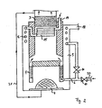
- Fig. 2 is an embodiment of the apparatus for generating represented by hydrogen according to the solution variant II.
- This also includes an allothermic, i. here provided with a gas burner 4 reformer 1 for conversion from hydrocarbon gas and water to hydrogen and others Reformer products.
- the reformer 1 is for chemical treatment the reformer products in this illustrated embodiment, but this is not mandatory, just a catalyst stage 3 downstream.
- a supply port 6 is provided over the during the starting phase of the apparatus only air can be fed, wherein the reformer 1 and the at least one Catalyst stage 3 are noble metal coated to not damaged by the ambient air used for preheating to become.
- This apparatus is operated as follows: via the educt feed connection 14 becomes the apparatus water and hydrocarbon gas fed. In the start phase, these educts arrive (via a centrally above the reformer arranged spiral heat exchanger 15 and one enclosing the core portion of the apparatus Wendelippo (2004)er 16) but only up to a valve disposed just before the supply port 6 (blocking means 10), which is an inflow of the educts to the reformer thus preventing the beginning of the reforming process.
- the reformer gets started only when starting with respect to the noble metal coated catalysts inert behaving Air supplied, on the one hand, from the also during the starting phase current burner absorbs incoming heat, so that of the uniformly heating reformer in this way not overheated, and the other when flowing on the spiral heat exchanger 15 and especially the downstream Catalyst stage 3 brings to operating temperature.
- the exhaust gas of the gas burner 4 flows in this solution variant II laterally over a concentric annular gap on the reformer. 1 past.
- the annular reformer 1 heated on both sides by the hot, effluent exhaust gas.
- the further Exhaust outflow area after the reformer 1 includes Annular gap space, in which the tubes of the helical heat exchanger 16th are arranged.
- the now somewhat colder exhaust gas is so efficiency-optimizing used for preheating the starting materials, in addition, but also by means of the helical heat exchanger 16 upstream and in the flow area of reformer products arranged spiral heat exchanger 15 are preheated.
- the preheat air during the starting phase not having to feed with a separate blower is further advantageously provided, the air connection of the gas burner. 4 by means of a connecting line 21 with the gas guide path to connect the reformer products, in order to create a pull effect cause an air intake at the air port 20 causes. But when it comes to the transition to stationary operation Make sure that the apparatus is cleared of air otherwise, when encountering the resulting hydrogen a detonating gas reaction could take place.
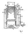
- FIG. 3 finally, an embodiment of the apparatus for Production of hydrogen according to the solution variant III shown.
- This also includes an allothermic working, provided with a gas burner 4 reformer 1 for conversion of hydrocarbon gas and water in hydrogen and other reformer products, with the reformer 1 to the chemical Preparation of the reformer products at least one catalyst stage 3 is connected downstream.
- a gas burner 4 downstream exhaust system 5 optional formed connected to the at least one catalyst stage 3 connectable is.
- To start the apparatus is from the gas burner. 4 Coming exhaust so long - with simultaneous suppression the educt feed to the reformer - via the exhaust passage 5 of the catalyst stage 3 supplied until both of the gas burner. 4 co-heated reformer 1 and as well as the catalyst stage 3rd Operating temperature have reached.
- the exhaust system 5 in the flow area of the reformer products between the reformer 1 and the catalyst stage 3 opens.
- the exhaust system from two mutually concentrically arranged Ringpalt matter 12, 13, via a connecting line 19 with each other are connected.
- the connection line 19 with a valve 17 for dividing the exhaust stream in provided two partial streams, namely a partial flow to the catalyst stage 3 and a partial flow to an exhaust gas discharge port 18.
- the entire exhaust gas flow at the beginning of the starting phase
- a part of the exhaust gas flow (during the starting phase) or no exhaust gas (in the stationary phase) Operation) are led to the catalyst stage.
- Constuctive is advantageous with respect to the supply port 6 provided that either the educts or the air (depending on Operating state) supplied to the reformer 1 via the supply port 6 become.
Landscapes
- Chemical & Material Sciences (AREA)
- Chemical Kinetics & Catalysis (AREA)
- Organic Chemistry (AREA)
- Engineering & Computer Science (AREA)
- Combustion & Propulsion (AREA)
- Inorganic Chemistry (AREA)
- Health & Medical Sciences (AREA)
- General Health & Medical Sciences (AREA)
- Physics & Mathematics (AREA)
- Thermal Sciences (AREA)
- Mechanical Engineering (AREA)
- General Engineering & Computer Science (AREA)
- Hydrogen, Water And Hydrids (AREA)
Description
- Fig. 1
- schematisch eine Ausführungsform der erfindungsgemäßen Lösungsvariante I;
- Fig. 2
- schematisch im Schnitt eine Ausführungsform der erfindungsgemäßen Lösungsvariante II und
- Fig. 3
- schematisch im Schnitt eine Ausführungsform der erfindungsgemäßen Lösungsvariante III.
- 1
- Reformer
- 2
- Eduktzufuhrstrecke
- 3
- Katalysatorstufe
- 4
- Gasbrenner
- 5
- Abgasführung
- 6
- Zufuhranschluss
- 7
- Wärmetauscher
- 8
- Zuführung
- 9
- Wärmetauscher
- 10
- Absperrmittel
- 11
- Verdampfer
- 12
- Ringspaltraum
- 13
- Ringspaltraum
- 14
- Eduktzufuhranschluss
- 15
- Spiralwärmetauscher
- 16
- Wendelwärmetauscher
- 17
- Stellklappe
- 18
- Abgasabfuhranschluss
- 19
- Verbindungsleitung
- 20
- Luftanschluss
- 21
- Verbindungsleitung
- 22
- Gebläseleitung
Claims (12)
- Verfahren zum Betrieb eines Apparats zur Erzeugung von Wasserstoff, bei dem im stationären Betrieb einem allotherm arbeitenden Reformer (1) über eine vorheizbare Eduktzufuhrstrecke (2) Kohlenwasserstoffgas und Wasser als Edukte zur Umwandlung in Wasserstoff und weitere Reformer-Produkte zugeführt werden, wobei dem Reformer (1) zur chemischen Aufbereitung der Reformer-Produkte mindestens eine Katalysatorstufe (3) nachgeschaltet ist,
dadurch gekennzeichnet, dass zum Starten des Apparats dem Reformer (1) solange ausschließlich Wasser zugeführt wird, bis der allotherm arbeitende Reformer (1) und die mindestens eine Katalysatorstufe (3) Betriebstemperatur erreicht haben. - Verfahren nach Anspruch 1,
dadurch gekennzeichnet, dass dem Reformer (1) das Wasser in der Startphase über die vorheizbare Eduktzufuhrstrecke (2) zugeführt wird. - Verfahren nach Anspruch 1 oder 2,
dadurch gekennzeichnet, dass das Wasser zum Vorheizen des Apparats vor Eintritt in den Reformer (1) verdampft wird. - Verfahren zum Betrieb eines Apparats zur Erzeugung von Wasserstoff, bei dem im stationären Betrieb einem allotherm arbeitenden Reformer (1) Kohlenwasserstoffgas und Wasser als Edukte zur Umwandlung in Wasserstoff und weitere Reformer-Produkte zugeführt werden, wobei dem Reformer (1) zur chemischen Aufbereitung der Reformer-Produkte mindestens eine Katalysatorstufe (3) nachgeschaltet ist,
dadurch gekennzeichnet, dass zum Starten des Apparats dem Reformer (1) über einen Zufuhranschluss (6) solange ausschließlich Luft zugeführt wird, bis der Reformer (1) und die mindestens eine edelmetallbeschichtete Katalysatorstufe (3) Betriebstemperatur erreicht haben. - Verfahren nach Anspruch 4,
dadurch gekennzeichnet, dass wahlweise die Edukte oder die Luft dem Reformer (1) über den Zufuhranschluss (6) zugeführt werden. - Verfahren zum Betrieb eines Apparats zur Erzeugung von Wasserstoff, bei dem im stationären Betrieb einem mit einem Gasbrenner (4) beheizten Reformer (1) Kohlenwasserstoffgas und Wasser als Edukte zur Umwandlung in Wasserstoff und weitere Reformer-Produkte zugeführt werden, wobei dem Reformer (1) zur chemischen Aufbereitung der Reformer-Produkte mindestens eine Katalysatorstufe (3) nachgeschaltet ist, wobei zum Starten des Apparats solange vom Gasbrenner (4) kommendes Abgas über eine Abgasführung (5) der mindestens einen Katalysatorstufe (3) zugeführt wird, bis der Reformer (1) und die mindestens eine Katalysatorstufe (3) Betriebstemperatur erreicht haben,
dadurch gekennzeichnet, dass beim Starten des Apparats dem Reformer (1) zum Schutz vor Überhitzung über einen Zufuhranschluss (6) zusätzlich Luft zugeführt wird. - Verfahren nach Anspruch 6,
dadurch gekennzeichnet, dass wahlweise die Edukte oder die Luft dem Reformer (1) über den Zufuhranschluss (6) zugeführt werden. - Apparat zur Durchführung des Verfahrens nach Anspruch 6, umfassend einen allotherm arbeitenden, mit einem Gasbrenner (4) versehenen Reformer (1) zur Umwandlung von Kohlenwasserstoffgas und Wasser in Wasserstoff und weitere Reformer-Produkte, wobei dem Reformer (1) zur chemischen Aufbereitung der Reformer-Produkte mindestens eine Katalysatorstufe (3) nachgeschaltet ist, wobei eine dem Gasbrenner (4) nachgeschaltete Abgasführung (5) je nach Betriebszustand mit der mindestens einen Katalysatorstufe (3) verbindbar ausgebildet ist,
dadurch gekennzeichnet, dass die Abgasführung (5) im Strömungsbereich der Reformer-Produkte zwischen dem Reformer (1) und der mindestens einen Katalysatorstufe (3) ausmündet. - Apparat nach Anspruch 8,
dadurch gekennzeichnet, dass die Abgasführung (5) mit einer Stellklappe (17) zur Aufteilung des Abgasstroms in zwei Teilströme versehen ist, nämlich einen Teilstrom zur mindestens einen Katalysatorstufe (3) und einen Teilstrom zu einem Abgasabfuhranschluss (18) . - Apparat nach Anspruch 8 oder 9,
dadurch gekennzeichnet , dass am Reformer (1) ein Zufuhranschluss (6) vorgesehen ist, über den diesem während der Startphase des Apparats Luft zuführbar ist, wobei der Reformer (1) und die mindestens eine Katalysatorstufe (3) edelmetallbeschichtet ausgebildet sind. - Apparat nach Anspruch 10,
dadurch gekennzeichnet, dass eine vorheizbare mit Absperrmitteln (10) versehene Eduktzufuhrstrecke (2) in den Zufuhranschluss (6) ausmündet, so dass wahlweise Luft oder Edukte über den Zufuhranschluss (6) dem Reformer (1) zuführbar sind. - Apparat nach Anspruch 10 oder 11,
dadurch gekennzeichnet, dass der Zufuhranschluss (6) zur Bereitstellung von Luft am Reformer (1) mit einer Luftfördereinrichtung, vorzugsweise mit einem Gebläse, versehen ist.
Applications Claiming Priority (2)
| Application Number | Priority Date | Filing Date | Title |
|---|---|---|---|
| DE2001132064 DE10132064A1 (de) | 2001-07-05 | 2001-07-05 | Verfahren zum Betrieb eines Apparats zur Erzeugung von Wasserstoff und Apparate zur Durchführung der Verfahren |
| DE10132064 | 2001-07-05 |
Publications (3)
| Publication Number | Publication Date |
|---|---|
| EP1273553A2 EP1273553A2 (de) | 2003-01-08 |
| EP1273553A3 EP1273553A3 (de) | 2003-10-22 |
| EP1273553B1 true EP1273553B1 (de) | 2005-09-14 |
Family
ID=7690361
Family Applications (1)
| Application Number | Title | Priority Date | Filing Date |
|---|---|---|---|
| EP20020014781 Expired - Lifetime EP1273553B1 (de) | 2001-07-05 | 2002-07-04 | Verfahren zum Betrieb eines Apparats zur Erzeugung von Wasserstoff und Apparate zur Durchführung der Verfahren |
Country Status (2)
| Country | Link |
|---|---|
| EP (1) | EP1273553B1 (de) |
| DE (2) | DE10132064A1 (de) |
Families Citing this family (3)
| Publication number | Priority date | Publication date | Assignee | Title |
|---|---|---|---|---|
| DE102004013337A1 (de) * | 2004-03-17 | 2005-10-13 | Viessmann Werke Gmbh & Co Kg | Brennstoffzellenanlage und Verfahren zum Betrieb dieser Anlage |
| DE102005030909A1 (de) * | 2005-06-30 | 2007-01-04 | Viessmann Werke Gmbh & Co Kg | Verfahren zum Starten und Abschalten einer Brennstoffzellenanlage |
| DE102006039039A1 (de) * | 2006-05-23 | 2007-11-29 | Zentrum für Brennstoffzellen-Technik GmbH | Verfahren zum Aufheizen einer Katalysatorstufe sowie Vorrichtung zum Durchführen des Verfahrens |
Family Cites Families (11)
| Publication number | Priority date | Publication date | Assignee | Title |
|---|---|---|---|---|
| US3909299A (en) * | 1973-10-01 | 1975-09-30 | United Technologies Corp | Fuel cell system including reform reactor |
| GB1491499A (en) * | 1973-11-23 | 1977-11-09 | Exxon Research Engineering Co | Process and catalyst for conversion of carbon monoxide and steam to hydrogen and carbon dioxide |
| JPS56159069A (en) * | 1980-05-14 | 1981-12-08 | Hitachi Ltd | Starting of fuel cell for electric power |
| US4473622A (en) * | 1982-12-27 | 1984-09-25 | Chludzinski Paul J | Rapid starting methanol reactor system |
| JP2511866B2 (ja) * | 1986-02-07 | 1996-07-03 | 株式会社日立製作所 | 燃料電池発電システム及びその起動方法 |
| JPH0333002A (ja) * | 1989-06-29 | 1991-02-13 | Hitachi Ltd | 水素製造装置 |
| US6096106A (en) * | 1990-04-03 | 2000-08-01 | The Standard Oil Company | Endothermic reaction apparatus |
| DE19727588C1 (de) * | 1997-06-28 | 1999-02-18 | Dbb Fuel Cell Engines Gmbh | Vorrichtung zur Erzeugung eines wasserstoffreichen und kohlenmonoxidarmen Gases |
| DE19755813C2 (de) * | 1997-12-16 | 2000-09-14 | Dbb Fuel Cell Engines Gmbh | Verfahren zum Betrieb einer Wasserdampfreformierungsanlage, damit betreibbare Reformierungsanlage und Brennstoffzellensystem-Betriebsverfahren |
| DE19755814C1 (de) * | 1997-12-16 | 1999-11-18 | Dbb Fuel Cell Engines Gmbh | Verfahren zum Betrieb einer Anlage zur Wasserdampfreformierung eines Kohlenwasserstoffs |
| JP2001106506A (ja) * | 1999-10-06 | 2001-04-17 | Mitsubishi Electric Corp | 改質器用燃焼装置 |
-
2001
- 2001-07-05 DE DE2001132064 patent/DE10132064A1/de not_active Ceased
-
2002
- 2002-07-04 DE DE50204225T patent/DE50204225D1/de not_active Expired - Lifetime
- 2002-07-04 EP EP20020014781 patent/EP1273553B1/de not_active Expired - Lifetime
Also Published As
| Publication number | Publication date |
|---|---|
| DE10132064A1 (de) | 2003-01-30 |
| EP1273553A2 (de) | 2003-01-08 |
| DE50204225D1 (de) | 2005-10-20 |
| EP1273553A3 (de) | 2003-10-22 |
Similar Documents
| Publication | Publication Date | Title |
|---|---|---|
| EP0921585B1 (de) | Vorrichtung und Verfahren zur Wasserdampfreformierung eines Kohlenwasserstoffs | |
| DE60215086T2 (de) | Brennstoffreformer und Methode zum Starten dieses Reformers | |
| EP0780917A1 (de) | Vorrichtung mit Brennstoffzellen | |
| EP1197258B1 (de) | Verfahren zum Betrieb einer Kraftwerksanlage | |
| EP0887306B1 (de) | Vorrichtung zur Erzeugung eines wasserstoffreichen und kohlenmonoxidarmen Gases | |
| DE102017001564B4 (de) | Verfahren zum Starten einer Brennstoffzellenanordnung und Brennstoffzellenanordnung | |
| DE10057537A1 (de) | Apparat zur Erzeugung von Wasserstoff | |
| EP1197256A1 (de) | Verfahren und Vorrichtung zur Erzeugung von heissen Verbrennungsabgasen | |
| EP2061113A1 (de) | Brennstoffzellensystem und Verfahren zu dessen Betrieb | |
| EP1197257B1 (de) | Verfahren und Vorrichtung zur Erzeugung heisser Arbeitsgase | |
| EP4496913B1 (de) | Hochtemperatur-co-elektrolysesystem, hochtemperatur-co-elektrolyseanlage und verfahren zum erzeugen von synthesegas | |
| EP1273553A2 (de) | Verfahren zum Betrieb eines Apparats zur Erzeugung von Wasserstoff und Apparate zur Durchführung der Verfahren | |
| EP3781521A1 (de) | Ammoniakanlage mit anfahrofen und verfahren zur herstellung von ammoniak | |
| EP1753061B1 (de) | Verfahren zum Starten einer Brennstoffzellenanlage | |
| DE102006019409B4 (de) | Reformer-Reaktor, seine Verwendung und Verfahren zum Betrieb des Reformers | |
| WO2020011311A1 (de) | Verfahren zum betreiben einer gasturbinenvorrichtung, gasturbinenvorrichtung und verwendung einer gasturbinenvorrichtung zur abgasreinigung | |
| EP4310160A1 (de) | Verfahren und anlage zum dampfspalten | |
| AT525145A1 (de) | Rezirkulationsvorrichtung für eine Rezirkulation von Anodenabgas als Rezirkulationsgas bei einem Brennstoffzellensystem | |
| DE10033593C1 (de) | Vorrichtung zur Erzeugung eines wasserstoffreichen Gases | |
| AT527536B1 (de) | Brennstoffzellensystem, Brennstoffzellenanlage und Verfahren zum Erzeugen von Synthesegas | |
| EP1415705A1 (de) | Apparat zur Erzeugung von Wasserstoff und Verfahren zum Betrieb eines solchen Apparats | |
| DE102010053572B4 (de) | Verfahren zum Betrieb eines Brennstoffzellensystems | |
| DE10239111B4 (de) | System zur Erzeugung eines wasserstoffhaltigen Gases zum Betreiben einer Brennstoffzelle | |
| DE10238988B4 (de) | Verfahren zum Betrieb eines Apparats zur Erzeugung von Wasserstoff und Apparat zur Erzeugung von Wasserstoff | |
| WO2020025163A1 (de) | Wärmerückgewinnungssystem für einen ofen mit einem oder mehreren brennern |
Legal Events
| Date | Code | Title | Description |
|---|---|---|---|
| PUAI | Public reference made under article 153(3) epc to a published international application that has entered the european phase |
Free format text: ORIGINAL CODE: 0009012 |
|
| AK | Designated contracting states |
Kind code of ref document: A2 Designated state(s): AT BE BG CH CY CZ DE DK EE ES FI FR GB GR IE IT LI LU MC NL PT SE SK TR |
|
| AX | Request for extension of the european patent |
Free format text: AL;LT;LV;MK;RO;SI |
|
| RIN1 | Information on inventor provided before grant (corrected) |
Inventor name: DZUBIELLA, MANFRED, DR. Inventor name: ZARTENAR, NICOLAS Inventor name: HOLTORF, JUERGEN, DR. Inventor name: BRITZ, PETER, DR. Inventor name: HEIKRODT, KLAUS, DR. |
|
| PUAL | Search report despatched |
Free format text: ORIGINAL CODE: 0009013 |
|
| AK | Designated contracting states |
Kind code of ref document: A3 Designated state(s): AT BE BG CH CY CZ DE DK EE ES FI FR GB GR IE IT LI LU MC NL PT SE SK TR |
|
| AX | Request for extension of the european patent |
Extension state: AL LT LV MK RO SI |
|
| RIC1 | Information provided on ipc code assigned before grant |
Ipc: 7C 01B 3/58 B Ipc: 7C 01B 3/48 B Ipc: 7F 28D 7/00 B Ipc: 7B 01J 8/04 B Ipc: 7H 01M 8/06 B Ipc: 7C 01B 3/38 A |
|
| 17P | Request for examination filed |
Effective date: 20040408 |
|
| AKX | Designation fees paid |
Designated state(s): DE FR GB IT NL |
|
| 17Q | First examination report despatched |
Effective date: 20040603 |
|
| RAP1 | Party data changed (applicant data changed or rights of an application transferred) |
Owner name: VIESSMANN WERKE GMBH & CO KG |
|
| GRAP | Despatch of communication of intention to grant a patent |
Free format text: ORIGINAL CODE: EPIDOSNIGR1 |
|
| GRAS | Grant fee paid |
Free format text: ORIGINAL CODE: EPIDOSNIGR3 |
|
| GRAA | (expected) grant |
Free format text: ORIGINAL CODE: 0009210 |
|
| AK | Designated contracting states |
Kind code of ref document: B1 Designated state(s): DE FR GB IT NL |
|
| REG | Reference to a national code |
Ref country code: GB Ref legal event code: FG4D Free format text: NOT ENGLISH |
|
| GBT | Gb: translation of ep patent filed (gb section 77(6)(a)/1977) |
Effective date: 20050914 |
|
| REF | Corresponds to: |
Ref document number: 50204225 Country of ref document: DE Date of ref document: 20051020 Kind code of ref document: P |
|
| ET | Fr: translation filed | ||
| PLBE | No opposition filed within time limit |
Free format text: ORIGINAL CODE: 0009261 |
|
| STAA | Information on the status of an ep patent application or granted ep patent |
Free format text: STATUS: NO OPPOSITION FILED WITHIN TIME LIMIT |
|
| 26N | No opposition filed |
Effective date: 20060615 |
|
| PGFP | Annual fee paid to national office [announced via postgrant information from national office to epo] |
Ref country code: NL Payment date: 20100625 Year of fee payment: 9 |
|
| PGFP | Annual fee paid to national office [announced via postgrant information from national office to epo] |
Ref country code: IT Payment date: 20100716 Year of fee payment: 9 |
|
| REG | Reference to a national code |
Ref country code: NL Ref legal event code: V1 Effective date: 20120201 |
|
| PG25 | Lapsed in a contracting state [announced via postgrant information from national office to epo] |
Ref country code: NL Free format text: LAPSE BECAUSE OF NON-PAYMENT OF DUE FEES Effective date: 20120201 Ref country code: IT Free format text: LAPSE BECAUSE OF NON-PAYMENT OF DUE FEES Effective date: 20110704 |
|
| PGFP | Annual fee paid to national office [announced via postgrant information from national office to epo] |
Ref country code: DE Payment date: 20130618 Year of fee payment: 12 |
|
| PGFP | Annual fee paid to national office [announced via postgrant information from national office to epo] |
Ref country code: FR Payment date: 20130731 Year of fee payment: 12 |
|
| PGFP | Annual fee paid to national office [announced via postgrant information from national office to epo] |
Ref country code: GB Payment date: 20131119 Year of fee payment: 12 |
|
| REG | Reference to a national code |
Ref country code: DE Ref legal event code: R119 Ref document number: 50204225 Country of ref document: DE |
|
| GBPC | Gb: european patent ceased through non-payment of renewal fee |
Effective date: 20140704 |
|
| REG | Reference to a national code |
Ref country code: FR Ref legal event code: ST Effective date: 20150331 |
|
| PG25 | Lapsed in a contracting state [announced via postgrant information from national office to epo] |
Ref country code: DE Free format text: LAPSE BECAUSE OF NON-PAYMENT OF DUE FEES Effective date: 20150203 |
|
| REG | Reference to a national code |
Ref country code: DE Ref legal event code: R119 Ref document number: 50204225 Country of ref document: DE Effective date: 20150203 |
|
| PG25 | Lapsed in a contracting state [announced via postgrant information from national office to epo] |
Ref country code: GB Free format text: LAPSE BECAUSE OF NON-PAYMENT OF DUE FEES Effective date: 20140704 Ref country code: FR Free format text: LAPSE BECAUSE OF NON-PAYMENT OF DUE FEES Effective date: 20140731 |