EP1273488B1 - Gasgenerator für einen Lenkradairbag - Google Patents
Gasgenerator für einen Lenkradairbag Download PDFInfo
- Publication number
- EP1273488B1 EP1273488B1 EP02009345A EP02009345A EP1273488B1 EP 1273488 B1 EP1273488 B1 EP 1273488B1 EP 02009345 A EP02009345 A EP 02009345A EP 02009345 A EP02009345 A EP 02009345A EP 1273488 B1 EP1273488 B1 EP 1273488B1
- Authority
- EP
- European Patent Office
- Prior art keywords
- gas generator
- spring element
- flange
- elements
- container
- Prior art date
- Legal status (The legal status is an assumption and is not a legal conclusion. Google has not performed a legal analysis and makes no representation as to the accuracy of the status listed.)
- Expired - Lifetime
Links
Images


Classifications
-
- B—PERFORMING OPERATIONS; TRANSPORTING
- B60—VEHICLES IN GENERAL
- B60R—VEHICLES, VEHICLE FITTINGS, OR VEHICLE PARTS, NOT OTHERWISE PROVIDED FOR
- B60R21/00—Arrangements or fittings on vehicles for protecting or preventing injuries to occupants or pedestrians in case of accidents or other traffic risks
- B60R21/02—Occupant safety arrangements or fittings, e.g. crash pads
- B60R21/16—Inflatable occupant restraints or confinements designed to inflate upon impact or impending impact, e.g. air bags
- B60R21/20—Arrangements for storing inflatable members in their non-use or deflated condition; Arrangement or mounting of air bag modules or components
- B60R21/203—Arrangements for storing inflatable members in their non-use or deflated condition; Arrangement or mounting of air bag modules or components in steering wheels or steering columns
- B60R21/2035—Arrangements for storing inflatable members in their non-use or deflated condition; Arrangement or mounting of air bag modules or components in steering wheels or steering columns using modules containing inflator, bag and cover attachable to the steering wheel as a complete sub-unit
Definitions
- the invention relates to a gas generator with a container for receiving the fuel cartridge for an airbag on the steering wheel of a motor vehicle, wherein the gas generator is designed as a vibration absorber and is connected via a gas-impermeable, the shape of a hollow cylinder or truncated cone having spring element made of polymeric material with the airbag housing and the connection between the spring element and the container and / or between the spring element and the airbag housing are formed as a positive snap connection or connections, wherein the spring element is designed as a separate insert and is provided at its edges with elements of the snap connection.
- Vibrating damper In motor vehicles vibrations can occur while driving or even at a standstill with a running engine, which are transmitted to the steering column and from there to the steering wheel. To counteract these vibrations and to improve ride comfort are Vibrating damper become known, in which the gas generator is used as oscillating mass.
- connection between the container of the gas generator and the mounting flange is the older DE 100 566 25
- the connection between the spring element and the gas generator container and / or the mounting flange are designed as a positive snap connection or / compounds.
- the spring element was designed as a frusto-conical hollow spring element, whereby an improved vibration behavior is achieved for the oscillating mass.
- the invention has for its object a safe and easy to produce connection possibility between the spring element and the gas generator container and / or between the spring element and airbag housing produce.
- the gas generator tank should be mounted as easily as possible within the airbag module on the steering wheel or even replaced. The function of the gas generator should not be affected.
- the solution of the object is achieved in a gas generator of the type mentioned invention, characterized in that the elements of the gas generator container have a flange-like shape and are provided with push-button-like plug or receiving parts in the corresponding receiving or plug-in parts of the gas generator and / or airbag housing existing connection flanges are on or plugged.
- the elements of the gas generator container have a flange-like shape and are provided with push-button-like plug or receiving parts in the corresponding receiving or plug-in parts of the gas generator and / or airbag housing existing connection flanges are on or plugged.
- the snap elements are made of metal, which are connected by vulcanization with the spring element.
- the spring element are connected by vulcanization with the spring element.
- particularly secure connections between the spring element and the gas generator container or airbag housing can be produced.
- the latter are to be provided with appropriate flanges for this purpose.
- a gas generator container 1 is shown, which is fastened by the spring element 2 on an airbag housing not shown in detail on the flange 3.
- the spring element 2 is designed as a hollow truncated cone and provided at its edges in each case with a flange 4 and 5.
- the flanges 4 and 5 are made of metal and connected to the spring element 2 by vulcanization.
- the flanges 4 and 5 are sub-elements of the snap connections 6 and 7.
- the flange 4 is provided on its circumference with a series of openings 8 into which the plugs 9 of the circumferential flange 3 are push-button inserted.
- the upper flange 5 of the spring element 2 in turn is provided with the stoppers 10 which are inserted into corresponding openings 11 of the flange 12.
- the flange 12 is fixedly attached to the container 1.
- the Fig. 2 shows a plan view of a construction according to the Fig. 1 ,
- the connection flange 3 is omitted from the airbag housing. Visible is the flange 4, distributed on the circumference of the openings 8 are provided for receiving the plug 9 of the flange 3. Only for completeness, it should be noted that any other connection, such as a screw connection between the flange 3 and the flange 4 via the openings 8 can be made here, provided that the flange 3 is also provided with the corresponding openings.
- the flange 12 is connected to the inflator container 1 via a shrink connection. For this purpose, the flange 12 is provided with a bead 13.
- the flange 12 also has openings 11 through which the plugs 10 of the flange 5 are inserted.
- the flange 5 is connected to the spring element 2 by vulcanization.
- At the stoppers 10 each have the lugs 14 are mounted, which engage in the insertion of the plug 10 into the openings 11 and in this way contribute to the special securing the snap connection.
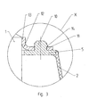
- Fig. 3 is on an enlarged scale of the detail x Fig. 1 shown.
- the flange 5 is vulcanized.
- the flange 5 is provided with the stoppers 10, which are inserted into the openings 11 in the flange 12.
- the flange 12 has the flanged edge 13 via which it is firmly connected to the gas generator container 1.
- the plugs 10 have the lugs 14 which engage in the openings 11 on the flange 12 upon insertion of the plug 10.
Landscapes
- Engineering & Computer Science (AREA)
- Mechanical Engineering (AREA)
- Air Bags (AREA)
Description
- Die Erfindung betrifft einen Gasgenerator mit einem Behälter zur Aufnahme der Treibstoffpatrone für einen Airbag am Lenkrad eines Kraftfahrzeuges, wobei der Gasgenerator als Schwingungstilger ausgebildet ist und über ein gasundurchlässiges, die Form eines hohlen Zylinders oder Kegelstumpfs aufweisenden Federelements aus polymerem Material mit dem Airbaggehäuse verbunden ist und die Verbindung zwischen dem Federelement und dem Behälter und/oder zwischen dem Federelement und dem Airbaggehäuse als formschlüssige Schnappverbindung beziehungsweise -verbindungen ausgebildet sind, wobei das Federelement als separater Einsatz ausgestaltet ist und an seinen Rändern mit Elementen der Schnappverbindung versehen ist.
- Bei Kraftfahrzeugen können während der Fahrt oder auch im Stillstand mit einem laufenden Motor Schwingungen auftreten, die sich auf die Lenksäule und von dort aus auf das Lenkrad übertragen. Um diesen Schwingungen entgegenzuwirken und den Fahrkomfort zu verbessern, sind Schwingungstilger bekannt geworden, bei denen der Gasgenerator als Schwingmasse verwendet wird.
- Durch das Gebrauchsmuster
DE 299 02 033 U1 ist ein Airbagmodul bekanntgeworden bei dem ein Montagezylinder aus einem elastischen Werkstoff verwendet wird, dessen Ränder einerseits mit einem am Gasgeneratorträger angeordneten ringförmigen Montageblech und andererseits mit einem mit dem Gehäuse des Gasgenerators verbundenen umlaufenden Montageflansch verbunden sind. Hierdurch wird eine gute Abdichtung für die aus dem Gasgenerator austretenden Gase und ein vertretbares Schwingungsverhalten erreicht. Die Verbindung zwischen dem Montagezylinder und dem Montageblech beziehungsweise Montageflansch ist jedoch nicht zufriedenstellend. Von Nachteil ist auch, dass eine nachträgliche Montage des Gasgenerators problematisch ist. - Eine andere Verbindungsmöglichkeit zwischen dem Behälter des Gasgenerator und dem Befestigungsflansch ist der älteren
DE 100 566 25 zu entnehmen, bei der die Verbindung zwischen dem Federelement und dem Gasgeneratorbehälter und/oder dem Befestigungsflansch als formschlüssige Schnappverbindung beziehungsweise /-verbindungen ausgebildet sind. Außerdem wurde das Federelement als kegelstumpfförmiges hohles Federelement ausgestaltet, wodurch ein verbessertes Schwingungsverhalten für die Schwingmasse erreicht wird. - Eine weitere Möglichkeit wird in der
EP 1 101 663 gezeigt. - Der Erfindung liegt die Aufgabe zugrunde eine sicher und einfach herstellbare Verbindungsmöglichkeit zwischen dem Federelement und dem Gasgeneratorbehälter und/oder zwischen dem Federelement und Airbaggehäuse herzustellen. Der Gasgeneratorbehälter soll möglichst leicht innerhalb des Airbagmoduls am Lenkrad montiert oder auch ausgetauscht werden können. Dabei soll die Funktion des Gasgenerators nicht beeinträchtigt werden.
- Die Lösung der gestellten Aufgabe erfolgt bei einem Gasgenerator der eingangs genannten Gattung erfindungsgemäß dadurch, dass die Elemente des Gasgeneratorbehälters eine flanschartige Form haben und mit druckknopfartigen Steck- oder Aufnahmeteilen versehen sind, die in korrespondierende Aufnahme- oder Steckteile von an dem Gasgeneratorbehälter und/oder Airbaggehäuse vorhandenen Anschlussflanschen ein- beziehungsweise aufsteckbar sind. Bei dieser Konstruktion ist es möglich, zunächst den Gasgeneratorbehälter herzustellen, mit einer Treibstofffüllung zu versehen und sodann in sehr einfacher Weise am Federelement zu befestigen. Das Federelement seinerseits kann vorher am Airbaggehäuse angebracht sein oder gegebenenfalls zusammen mit dem Gasgenerator in die im Airbaggehäuse vorhandene Öffnung eingefügt und dann am Airbaggehäuse befestigt werden. In der einfachsten Ausführungsform kann das Federelement und seine Elemente für die Schnappverbindung aus dem gleichen Material hergestellt sein. Hierdurch ergibt sich ein besonders einfaches Herstellverfahren für das Federelement und die daran angebrachten Schnappelemente.
- Möglich ist aber auch, dass die Schnappelemente aus Metall bestehen, die durch Vulkanisation mit dem Federelement verbunden sind. Hierdurch können besonders sichere Verbindungen zwischen dem Federelement und dem Gasgeneratorbehälter beziehungsweise Airbaggehäuse hergestellt werden. Letztere sind hierfür mit entsprechenden Flanschen zu versehen.
- In der Zeichnung ist ein Ausführungsbeispiel dargestellt. Es zeigt:
- Fig. 1
- einen Gasgeneratorbehälter in der Seitenansicht und seine Halterung durch ein Federelement wobei letzteres im Schnitt gezeigt ist.
- Fig. 2
- eine Draufsicht auf den Gasgenerator mit Federelement und
- Fig. 3
- das Detail x aus der
Fig. 1 in vergrößertem Maßstab. - In der
Fig. 1 ist ein Gasgeneratorbehälter 1 gezeigt, der von dem Federelement 2 an einem im Detail nicht näher gezeigten Airbaggehäuse über den Flansch 3 befestigt ist. Das Federelement 2 ist als hohler Kegelstumpf ausgestaltet und an seinen Rändern jeweils mit einem Flansch 4 und 5 versehen. Im Ausführungsbeispiel sind die Flansche 4 und 5 aus Metall und mit dem Federelement 2 durch Vulkanisation verbunden. Die Flansche 4 und 5 sind Teilelemente der Schnappverbindungen 6 und 7. Hierfür ist der Flansch 4 auf seinem Umfang mit einer Reihe von Öffnungen 8 versehen, in die die Stöpsel 9 des rundumlaufenden Flansches 3 druckknopfartig einsteckbar sind. Der obere Flansch 5 des Federelements 2 ist seinerseits mit den Stöpseln 10 versehen, die in entsprechende Öffnungen 11 des Flansches 12 eingesteckt sind. Der Flansch 12 ist am Behälter 1 fest angebracht. - Die
Fig. 2 zeigt eine Draufsicht auf eine Konstruktion nach derFig. 1 . Dabei ist der Anschlussflansch 3 zum Airbaggehäuse weggelassen. Sichtbar ist der Flansch 4, auf dessen Umfang verteilt die Öffnungen 8 für die Aufnahme der Stöpsel 9 des Flansches 3 vorgesehen sind. Nur der Vollständigkeit halber sei bemerkt, dass hier auch jede andere Verbindung, z.B. eine Schraubverbindung zwischen dem Flansch 3 und dem Flansch 4 über die Öffnungen 8 vorgenommen werden kann, sofern der Flansch 3 ebenfalls mit den entsprechenden Öffnungen versehen ist. Der Flansch 12 ist mit dem Gasgeneratorbehälter 1 über eine Schrumpfverbindung verbunden. Hierfür ist der Flansch 12 mit einem Bördelrand 13 versehen. Der Flansch 12 hat ebenfalls Öffnungen 11, durch die die Stöpsel 10 des Flansches 5 gesteckt sind. Der Flansch 5 ist durch Vulkanisation mit dem Federelement 2 verbunden. An den Stöpseln 10 sind jeweils die Nasen 14 angebracht, die beim Einstecken der Stöpsel 10 in die Öffnungen 11 einrasten und auf diese Weise zur besonderen Sicherung der Schnappverbindung beitragen. - In der
Fig. 3 ist in vergrößertem Maßstab des Detail x ausFig. 1 gezeigt. Am Federelement 2 ist der Flansch 5 anvulkanisiert. Der Flansch 5 ist mit den Stöpseln 10 versehen, welche in die Öffnungen 11 im Flansch 12 eingesteckt sind. Der Flansch 12 hat die Bördelkante 13 über die er fest mit dem Gasgeneratorbehälter 1 verbunden ist. Die Stöpsel 10 haben die Nasen 14, die beim Einstecken der Stöpsel 10 in die Öffnungen 11 am Flansch 12 einrasten.
Claims (5)
- Gasgenerator mit einem Behälter zur Aufnahme der Treibstoffpatrone für einen Airbag am Lenkrad eines Kraftfahrzeugs, wobei der Gasgenerator als Schwingungstilger ausgebildet ist und über ein gasundurchlässiges, die Form eines hohlen Zylinders oder Kegelstumpfs aufweisenden Federelements aus polymerem Material mit dem Airbaggehäuse verbunden ist, und die Verbindung zwischen dem Federelement und dem Behälter und/oder zwischen dem Federelement und Airbaggehäuse als formschlüssige Schnappverbindung bzw. -verbindungen ausgebildet sind, wobei das Federelement als separater Einsatz ausgestaltet ist und an seinen Rändern mit rundumlaufenden Elementen der Schnappverbindung versehen ist, dadurch gekennzeichnet, dass die Elemente (4, 5) eine flanschartige Form haben und mit druckknopfartigen Steck- oder Aufnahmeteilen (9, 10; 8; 11) versehen sind, die in bzw. auf korrespondierende Aufnahme- oder Steckteile (8, 9, 10, 11) von an dem Gasgeneratorbehälter (1) und/oder Airbaggehäuse vorhandene Anschlussflansche (3, 12) ein- beziehungsweise aufsteckbar sind.
- Gasgenerator nach Anspruch 1, dadurch gekennzeichnet, dass die Elemente (4,5) und das Federelement (2) aus dem gleichen Material sind.
- Gasgenerator nach Anspruch 1, dadurch gekennzeichnet, dass die Elemente (4,5) aus Metall sind.
- Gasgenerator nach Anspruch 3, dadurch gekennzeichnet, dass die Elemente (4, 5) durch Vulkanisation mit dem Federelement (2) verbunden sind.
- Gasgenerator nach einem der Ansprüche 1 bis 4, dadurch gekennzeichnet, dass die Steckteile (9, 10) mit Einrastnasen (14) versehen sind.
Applications Claiming Priority (2)
| Application Number | Priority Date | Filing Date | Title |
|---|---|---|---|
| DE10132394A DE10132394A1 (de) | 2001-07-06 | 2001-07-06 | Gasgenerator für einen Lenkradairbag |
| DE10132394 | 2001-07-06 |
Publications (3)
| Publication Number | Publication Date |
|---|---|
| EP1273488A2 EP1273488A2 (de) | 2003-01-08 |
| EP1273488A3 EP1273488A3 (de) | 2004-01-02 |
| EP1273488B1 true EP1273488B1 (de) | 2011-10-12 |
Family
ID=7690570
Family Applications (1)
| Application Number | Title | Priority Date | Filing Date |
|---|---|---|---|
| EP02009345A Expired - Lifetime EP1273488B1 (de) | 2001-07-06 | 2002-05-03 | Gasgenerator für einen Lenkradairbag |
Country Status (3)
| Country | Link |
|---|---|
| EP (1) | EP1273488B1 (de) |
| JP (1) | JP2003034218A (de) |
| DE (1) | DE10132394A1 (de) |
Families Citing this family (5)
| Publication number | Priority date | Publication date | Assignee | Title |
|---|---|---|---|---|
| DE20304551U1 (de) | 2003-03-21 | 2003-07-31 | TRW Automotive Safety Systems GmbH, 63743 Aschaffenburg | Gassackmodul für ein Kraftfahrzeuglenkrad mit schwingfähig gelagertem Gasgenerator |
| DE102011012871B4 (de) | 2010-03-02 | 2015-05-13 | Carl Freudenberg Kg | Einrichtung zur Verbindung eines Gasgenerators mit einem Airbag-Gehäuse |
| DE102012101396B3 (de) * | 2012-02-21 | 2013-05-16 | WEGU Holding GmbH | Elastische Ankopplung einer einen Flansch aufweisenden Baueinheit, um einen passiven Schwingungstilger auszubilden |
| DE202016105537U1 (de) * | 2016-10-05 | 2016-10-24 | Vibracoustic Gmbh | Schwingungstilger |
| DE102017114301A1 (de) * | 2017-06-28 | 2019-01-03 | Trw Automotive Safety Systems Gmbh | Schwingungstilgerring sowie gassackmodul mit einem solchen schwingungstilgerring |
Family Cites Families (6)
| Publication number | Priority date | Publication date | Assignee | Title |
|---|---|---|---|---|
| US6164689A (en) * | 1996-01-16 | 2000-12-26 | Ford Global Technologies, Inc. | Vibration absorbing apparatus for steering wheel with an airbag |
| DE29816923U1 (de) * | 1998-09-16 | 1998-11-26 | Petri Ag, 63743 Aschaffenburg | Lenkrad mit Airbagmodul |
| DE29902033U1 (de) * | 1999-02-05 | 1999-04-08 | TRW Automotive Safety Systems GmbH, 63743 Aschaffenburg | Airbagmodul als Schwingungsdämpfer |
| DE19955426B4 (de) * | 1999-11-18 | 2005-11-10 | Carl Freudenberg Kg | Gasgenerator für einen Airbag |
| DE19955427A1 (de) * | 1999-11-18 | 2001-06-07 | Freudenberg Carl Fa | Airbaggehäuse in einem Kraftfahrzeuglenkrad |
| DE10056625A1 (de) | 2000-11-15 | 2002-06-06 | Freudenberg Carl Kg | Gasgenerator für einen Lenkradairbag eines Kraftfahrzeugs |
-
2001
- 2001-07-06 DE DE10132394A patent/DE10132394A1/de not_active Withdrawn
-
2002
- 2002-05-03 EP EP02009345A patent/EP1273488B1/de not_active Expired - Lifetime
- 2002-07-05 JP JP2002197144A patent/JP2003034218A/ja active Pending
Non-Patent Citations (1)
| Title |
|---|
| None * |
Also Published As
| Publication number | Publication date |
|---|---|
| JP2003034218A (ja) | 2003-02-04 |
| EP1273488A2 (de) | 2003-01-08 |
| EP1273488A3 (de) | 2004-01-02 |
| DE10132394A1 (de) | 2003-01-23 |
Similar Documents
| Publication | Publication Date | Title |
|---|---|---|
| DE19955426B4 (de) | Gasgenerator für einen Airbag | |
| DE102011017350B4 (de) | Vorrichtung zur Dämpfung von Schwingungen | |
| DE19581552B4 (de) | Lenkrad mit vormontiertem Airbagmodul | |
| EP3113986A1 (de) | Rastzapfen zur besfestigung eines gassackmoduls an einem kraftfahrzeug | |
| DE102012002433B4 (de) | Dämpferlager für eine Kolbenstange eines Schwingungsdämpfers sowie Kraftfahrzeug mit einem solchen Dämpferlager | |
| DE10131830B4 (de) | Befestigung eines Topfgasgenerators an einer kegelstumpfförmigen Elastomerfeder | |
| DE19908915B4 (de) | Schwingungstilger für ein Lenkrad mit einem Airbag | |
| DE10156424A1 (de) | Luftsackmodul für Kraftfahrzeuge | |
| EP1535810B1 (de) | Gasgenerator | |
| EP0584528B1 (de) | Deckel für Bleiakkumulator mit Entgasungssystem | |
| DE10110912B4 (de) | Airbagmodul für ein Lenkrad eines Kraftfahrzeugs | |
| EP1238869A1 (de) | Gasgenerator für einen Airbag am Lenkrad eines Kraftfahrzeuges | |
| DE19743615B4 (de) | Airbagbaueinheit | |
| EP1273488A2 (de) | Gasgenerator für einen Lenkradairbag | |
| DE10002480B4 (de) | Airbagmodul für ein Kraftfahrzeuglenkrad | |
| DE10056625A1 (de) | Gasgenerator für einen Lenkradairbag eines Kraftfahrzeugs | |
| EP2419305A1 (de) | Gassackanordnung für ein fahrzeuginsassen-rückhaltesystem und verfahren zum herstellen einer gassackanordnung | |
| DE19955427A1 (de) | Airbaggehäuse in einem Kraftfahrzeuglenkrad | |
| DE102011012871B4 (de) | Einrichtung zur Verbindung eines Gasgenerators mit einem Airbag-Gehäuse | |
| DE102004038023B4 (de) | Schwingungstilger | |
| DE19929963B4 (de) | Lenkrad mit Airbag-Modul | |
| DE102004005211B4 (de) | Ringförmiges Filterelement und zugehöriges Herstellungsverfahren | |
| DE10019082B4 (de) | Träger für eine Vorrichtung zum Messen des Reifendrucks zur Verwendung in einem auf einer Felge montierten Luftreifen und damit ausgestattetes Rad | |
| DE19908916A1 (de) | Schwingungstilger für Lenkräder von Kraftfahrzeugen | |
| AT401085B (de) | Verschlussanordnung |
Legal Events
| Date | Code | Title | Description |
|---|---|---|---|
| PUAI | Public reference made under article 153(3) epc to a published international application that has entered the european phase |
Free format text: ORIGINAL CODE: 0009012 |
|
| AK | Designated contracting states |
Kind code of ref document: A2 Designated state(s): AT BE CH CY DE DK ES FI FR GB GR IE IT LI LU MC NL PT SE TR |
|
| AX | Request for extension of the european patent |
Free format text: AL;LT;LV;MK;RO;SI PAYMENT 20020510 |
|
| PUAL | Search report despatched |
Free format text: ORIGINAL CODE: 0009013 |
|
| AK | Designated contracting states |
Kind code of ref document: A3 Designated state(s): AT BE CH CY DE DK ES FI FR GB GR IE IT LI LU MC NL PT SE TR |
|
| AX | Request for extension of the european patent |
Extension state: AL LT LV MK RO SI |
|
| 17P | Request for examination filed |
Effective date: 20031204 |
|
| AKX | Designation fees paid |
Designated state(s): DE ES FR GB SE |
|
| AXX | Extension fees paid |
Extension state: SI Payment date: 20020510 |
|
| 17Q | First examination report despatched |
Effective date: 20070214 |
|
| GRAP | Despatch of communication of intention to grant a patent |
Free format text: ORIGINAL CODE: EPIDOSNIGR1 |
|
| GRAS | Grant fee paid |
Free format text: ORIGINAL CODE: EPIDOSNIGR3 |
|
| RIN1 | Information on inventor provided before grant (corrected) |
Inventor name: DUERRE, MARKUS Inventor name: LEIBACH, MARKUS Inventor name: BACK, FRIEDERICH Inventor name: BERG, THILO |
|
| GRAA | (expected) grant |
Free format text: ORIGINAL CODE: 0009210 |
|
| AK | Designated contracting states |
Kind code of ref document: B1 Designated state(s): DE ES FR GB SE |
|
| AX | Request for extension of the european patent |
Extension state: SI |
|
| REG | Reference to a national code |
Ref country code: GB Ref legal event code: FG4D Free format text: NOT ENGLISH |
|
| REG | Reference to a national code |
Ref country code: DE Ref legal event code: R081 Ref document number: 50215237 Country of ref document: DE Owner name: VIBRACOUSTIC GMBH, DE Free format text: FORMER OWNER: CARL FREUDENBERG KG, 69469 WEINHEIM, DE |
|
| REG | Reference to a national code |
Ref country code: DE Ref legal event code: R096 Ref document number: 50215237 Country of ref document: DE Effective date: 20111201 |
|
| PG25 | Lapsed in a contracting state [announced via postgrant information from national office to epo] |
Ref country code: SE Free format text: LAPSE BECAUSE OF FAILURE TO SUBMIT A TRANSLATION OF THE DESCRIPTION OR TO PAY THE FEE WITHIN THE PRESCRIBED TIME-LIMIT Effective date: 20111012 |
|
| PLBE | No opposition filed within time limit |
Free format text: ORIGINAL CODE: 0009261 |
|
| STAA | Information on the status of an ep patent application or granted ep patent |
Free format text: STATUS: NO OPPOSITION FILED WITHIN TIME LIMIT |
|
| 26N | No opposition filed |
Effective date: 20120713 |
|
| REG | Reference to a national code |
Ref country code: DE Ref legal event code: R097 Ref document number: 50215237 Country of ref document: DE Effective date: 20120713 |
|
| GBPC | Gb: european patent ceased through non-payment of renewal fee |
Effective date: 20120503 |
|
| REG | Reference to a national code |
Ref country code: FR Ref legal event code: ST Effective date: 20130131 |
|
| PG25 | Lapsed in a contracting state [announced via postgrant information from national office to epo] |
Ref country code: FR Free format text: LAPSE BECAUSE OF NON-PAYMENT OF DUE FEES Effective date: 20120531 Ref country code: ES Free format text: LAPSE BECAUSE OF FAILURE TO SUBMIT A TRANSLATION OF THE DESCRIPTION OR TO PAY THE FEE WITHIN THE PRESCRIBED TIME-LIMIT Effective date: 20120123 Ref country code: GB Free format text: LAPSE BECAUSE OF NON-PAYMENT OF DUE FEES Effective date: 20120503 |
|
| REG | Reference to a national code |
Ref country code: DE Ref legal event code: R081 Ref document number: 50215237 Country of ref document: DE Owner name: VIBRACOUSTIC GMBH, DE Free format text: FORMER OWNER: CARL FREUDENBERG KG, 69469 WEINHEIM, DE |
|
| PGFP | Annual fee paid to national office [announced via postgrant information from national office to epo] |
Ref country code: DE Payment date: 20180629 Year of fee payment: 17 |
|
| REG | Reference to a national code |
Ref country code: DE Ref legal event code: R119 Ref document number: 50215237 Country of ref document: DE |
|
| PG25 | Lapsed in a contracting state [announced via postgrant information from national office to epo] |
Ref country code: DE Free format text: LAPSE BECAUSE OF NON-PAYMENT OF DUE FEES Effective date: 20191203 |