EP1273471A2 - Wheather strip for automobile and continuous extrusion molding system for molding same - Google Patents
Wheather strip for automobile and continuous extrusion molding system for molding same Download PDFInfo
- Publication number
- EP1273471A2 EP1273471A2 EP02013757A EP02013757A EP1273471A2 EP 1273471 A2 EP1273471 A2 EP 1273471A2 EP 02013757 A EP02013757 A EP 02013757A EP 02013757 A EP02013757 A EP 02013757A EP 1273471 A2 EP1273471 A2 EP 1273471A2
- Authority
- EP
- European Patent Office
- Prior art keywords
- weather strip
- rubber portion
- solid rubber
- core bar
- foamed solid
- Prior art date
- Legal status (The legal status is an assumption and is not a legal conclusion. Google has not performed a legal analysis and makes no representation as to the accuracy of the status listed.)
- Granted
Links
- 238000001125 extrusion Methods 0.000 title claims abstract description 30
- 238000000465 moulding Methods 0.000 title abstract description 7
- 229920001971 elastomer Polymers 0.000 claims abstract description 57
- 239000007787 solid Substances 0.000 claims abstract description 54
- 230000005484 gravity Effects 0.000 claims abstract description 7
- 239000011248 coating agent Substances 0.000 claims description 12
- 238000000576 coating method Methods 0.000 claims description 12
- 229920002725 thermoplastic elastomer Polymers 0.000 claims description 11
- 239000011347 resin Substances 0.000 claims description 10
- 229920005992 thermoplastic resin Polymers 0.000 claims description 9
- 239000011800 void material Substances 0.000 abstract description 13
- 150000001336 alkenes Chemical class 0.000 description 2
- 230000006866 deterioration Effects 0.000 description 2
- 239000000463 material Substances 0.000 description 2
- JRZJOMJEPLMPRA-UHFFFAOYSA-N olefin Natural products CCCCCCCC=C JRZJOMJEPLMPRA-UHFFFAOYSA-N 0.000 description 2
- 229920005989 resin Polymers 0.000 description 2
- 238000004073 vulcanization Methods 0.000 description 2
- 239000004604 Blowing Agent Substances 0.000 description 1
- 230000015572 biosynthetic process Effects 0.000 description 1
- 230000000903 blocking effect Effects 0.000 description 1
- 238000007599 discharging Methods 0.000 description 1
- 238000004049 embossing Methods 0.000 description 1
- 230000002708 enhancing effect Effects 0.000 description 1
- 230000001747 exhibiting effect Effects 0.000 description 1
- 238000005187 foaming Methods 0.000 description 1
- 239000011521 glass Substances 0.000 description 1
- 239000004033 plastic Substances 0.000 description 1
Images


Classifications
-
- B—PERFORMING OPERATIONS; TRANSPORTING
- B60—VEHICLES IN GENERAL
- B60J—WINDOWS, WINDSCREENS, NON-FIXED ROOFS, DOORS, OR SIMILAR DEVICES FOR VEHICLES; REMOVABLE EXTERNAL PROTECTIVE COVERINGS SPECIALLY ADAPTED FOR VEHICLES
- B60J5/00—Doors
-
- B—PERFORMING OPERATIONS; TRANSPORTING
- B60—VEHICLES IN GENERAL
- B60J—WINDOWS, WINDSCREENS, NON-FIXED ROOFS, DOORS, OR SIMILAR DEVICES FOR VEHICLES; REMOVABLE EXTERNAL PROTECTIVE COVERINGS SPECIALLY ADAPTED FOR VEHICLES
- B60J10/00—Sealing arrangements
- B60J10/80—Sealing arrangements specially adapted for opening panels, e.g. doors
-
- B—PERFORMING OPERATIONS; TRANSPORTING
- B29—WORKING OF PLASTICS; WORKING OF SUBSTANCES IN A PLASTIC STATE IN GENERAL
- B29C—SHAPING OR JOINING OF PLASTICS; SHAPING OF MATERIAL IN A PLASTIC STATE, NOT OTHERWISE PROVIDED FOR; AFTER-TREATMENT OF THE SHAPED PRODUCTS, e.g. REPAIRING
- B29C48/00—Extrusion moulding, i.e. expressing the moulding material through a die or nozzle which imparts the desired form; Apparatus therefor
- B29C48/001—Combinations of extrusion moulding with other shaping operations
- B29C48/0022—Combinations of extrusion moulding with other shaping operations combined with cutting
-
- B—PERFORMING OPERATIONS; TRANSPORTING
- B60—VEHICLES IN GENERAL
- B60J—WINDOWS, WINDSCREENS, NON-FIXED ROOFS, DOORS, OR SIMILAR DEVICES FOR VEHICLES; REMOVABLE EXTERNAL PROTECTIVE COVERINGS SPECIALLY ADAPTED FOR VEHICLES
- B60J10/00—Sealing arrangements
- B60J10/15—Sealing arrangements characterised by the material
- B60J10/18—Sealing arrangements characterised by the material provided with reinforcements or inserts
-
- B—PERFORMING OPERATIONS; TRANSPORTING
- B29—WORKING OF PLASTICS; WORKING OF SUBSTANCES IN A PLASTIC STATE IN GENERAL
- B29C—SHAPING OR JOINING OF PLASTICS; SHAPING OF MATERIAL IN A PLASTIC STATE, NOT OTHERWISE PROVIDED FOR; AFTER-TREATMENT OF THE SHAPED PRODUCTS, e.g. REPAIRING
- B29C2793/00—Shaping techniques involving a cutting or machining operation
- B29C2793/0063—Cutting longitudinally
-
- B—PERFORMING OPERATIONS; TRANSPORTING
- B29—WORKING OF PLASTICS; WORKING OF SUBSTANCES IN A PLASTIC STATE IN GENERAL
- B29C—SHAPING OR JOINING OF PLASTICS; SHAPING OF MATERIAL IN A PLASTIC STATE, NOT OTHERWISE PROVIDED FOR; AFTER-TREATMENT OF THE SHAPED PRODUCTS, e.g. REPAIRING
- B29C48/00—Extrusion moulding, i.e. expressing the moulding material through a die or nozzle which imparts the desired form; Apparatus therefor
- B29C48/03—Extrusion moulding, i.e. expressing the moulding material through a die or nozzle which imparts the desired form; Apparatus therefor characterised by the shape of the extruded material at extrusion
- B29C48/12—Articles with an irregular circumference when viewed in cross-section, e.g. window profiles
-
- B—PERFORMING OPERATIONS; TRANSPORTING
- B29—WORKING OF PLASTICS; WORKING OF SUBSTANCES IN A PLASTIC STATE IN GENERAL
- B29C—SHAPING OR JOINING OF PLASTICS; SHAPING OF MATERIAL IN A PLASTIC STATE, NOT OTHERWISE PROVIDED FOR; AFTER-TREATMENT OF THE SHAPED PRODUCTS, e.g. REPAIRING
- B29C48/00—Extrusion moulding, i.e. expressing the moulding material through a die or nozzle which imparts the desired form; Apparatus therefor
- B29C48/15—Extrusion moulding, i.e. expressing the moulding material through a die or nozzle which imparts the desired form; Apparatus therefor incorporating preformed parts or layers, e.g. extrusion moulding around inserts
- B29C48/154—Coating solid articles, i.e. non-hollow articles
-
- Y—GENERAL TAGGING OF NEW TECHNOLOGICAL DEVELOPMENTS; GENERAL TAGGING OF CROSS-SECTIONAL TECHNOLOGIES SPANNING OVER SEVERAL SECTIONS OF THE IPC; TECHNICAL SUBJECTS COVERED BY FORMER USPC CROSS-REFERENCE ART COLLECTIONS [XRACs] AND DIGESTS
- Y10—TECHNICAL SUBJECTS COVERED BY FORMER USPC
- Y10T—TECHNICAL SUBJECTS COVERED BY FORMER US CLASSIFICATION
- Y10T428/00—Stock material or miscellaneous articles
- Y10T428/24—Structurally defined web or sheet [e.g., overall dimension, etc.]
- Y10T428/2419—Fold at edge
- Y10T428/24198—Channel-shaped edge component [e.g., binding, etc.]
-
- Y—GENERAL TAGGING OF NEW TECHNOLOGICAL DEVELOPMENTS; GENERAL TAGGING OF CROSS-SECTIONAL TECHNOLOGIES SPANNING OVER SEVERAL SECTIONS OF THE IPC; TECHNICAL SUBJECTS COVERED BY FORMER USPC CROSS-REFERENCE ART COLLECTIONS [XRACs] AND DIGESTS
- Y10—TECHNICAL SUBJECTS COVERED BY FORMER USPC
- Y10T—TECHNICAL SUBJECTS COVERED BY FORMER US CLASSIFICATION
- Y10T428/00—Stock material or miscellaneous articles
- Y10T428/24—Structurally defined web or sheet [e.g., overall dimension, etc.]
- Y10T428/24273—Structurally defined web or sheet [e.g., overall dimension, etc.] including aperture
- Y10T428/24322—Composite web or sheet
Definitions
- the invention relates to a weather strip for an automobile, comprising a slightly foamed solid rubber portion with a core bar embedded therein, and a continuous extrusion molding system for molding the same.
- a weather strip 20 for an automobile comprising a U-shaped trim 2 formed by embedding a core bar 4 in a slightly foamed solid rubber portion 3, is molded with a continuous extrusion molding system, a void 21 is prone to occur to a boundary part between the core bar 4 and the slightly foamed solid rubber portion 3 due to a gas pocket formed.
- a blowing agent contained in the slightly foamed solid rubber portion 3 is gasified as a result of being heated up by heat generated at the time of extrusion molding with an extruder 11, and being heated up in a vulcanizing furnace 15, and gas thus generated in part of the slightly foamed solid rubber portion 3, in close proximity to the core bar 4, is not turned into bubbles, thereby gathering towards the core bar 4.
- the void 21 tends to occur in a groove bottom 3a of a U-like shape of a part of the slightly foamed solid rubber portion 3, substantially resembling the letter U, taking a tunnel form at times, or occurring at a number of successive places to a size in the order of 5 mm at other times.
- the slightly foamed solid rubber portion 3 is peeled off from the core bar 4, and will be in floating condition, causing difficulty with conveying holding force of rubber to the core bar 4 when pushing out the core bar 4 at the time of extrusion molding, that is, at the time of breakout, so that the breakout of the core bar 4 can not be implemented with ease.
- the surface of the slightly foamed solid rubber portion 3 is prone to be marred with holding marks, thereby aggravating external appearance .
- presence of the void 21 interferes with attachment of the weather strip to a flange. Further, if the void 21 occurs to an outer part 3b of the solid rubber portion 3, this also will result in poor external appearance .
- thermoplastic elastomer comprises a rubber component (soft segment) for exhibiting elasticity, and a resin component (hard segment) for fluidizing at a high temperature and blocking plastic deformation at room temperature, and the same is material that can be plasticized at high temperature to be molded in the same way as a thermoplastic resin.
- a thermoplastic elastomer containing olefin-based components is called an olefin thermoplastic elastomer (referred to as TPO).
- the void 21 is prone to occur to the boundary part between the core bar 4 and the slightly foamed solid rubber portion 3, and interferes with the attachment of the weather strip to the flange, resulting in poor external appearance. It is therefore an object of the invention to provide a weather strip causing no such problems, and a continuous extrusion molding system for molding the same.
- a weather strip 1 for an automobile comprising a U-shaped trim 2 formed by embedding a core bar 4 in a slightly foamed solid rubber portion 3, foamed so as to have a specific gravity of 0.8 to 1.2, wherein tiny holes 7 having a depth reaching the core bar 4 are defined in part of the slightly foamed solid rubber portion 3, within the U-shaped trim 2, in such a way as to be arranged in line along the longitudinal direction of the weather strip 1.
- tiny holes 7 having a depth reaching the core bar 4 are defined in a groove bottom of a U-like shape of part of the slightly foamed solid rubber portion, within the U-shaped trim, in such a way as to be arranged in line along the longitudinal direction of the weather strip 1.
- tiny holes 7 having a depth reaching the core bar 4 may be defined in an outer part 3b of the slightly foamed solid rubber portion 3, visible from outside, in such a way as to be arranged in line along the longitudinal direction of the weather strip 1, and the tiny holes 7 are preferably sealed with a coating 8 formed of a thermoplastic elastomer or resin.
- the invention provides in its second aspect a continuous extrusion molding system 10 for continuously extrusion molding a weather strip 1 for an automobile, comprising the U-shaped trim 2 formed by embedding a core bar 4 in a slightly foamed solid rubber portion 3, comprising a prickly gear 13, rotatable while pressed in contact with the weather strip 1 being extruded, and disposed so as to be adjacent to a mouth piece 12 of an extruder 11, wherein tiny holes 7 having a depth reaching the core bar 4 are defined in part of the slightly foamed solid rubber portion 3, within the U-shaped trim 2, in such a way as to be arranged in line along the longitudinal direction of the weather strip 1 by use of the prickly gear 13.
- tiny holes 7 may be sealed with a coating 8 formed of a thermoplastic elastomer or resin, formed on the surface of the slightly foamed solid rubber portion 3, by use of a coating unit 16 after the tiny holes 7 having the depth reaching the core bar 4 are defined in part of the slightly foamed solid rubber portion 3, within the U-shaped trim 2, in such a way as to be arranged in line along the longitudinal direction of the weather strip 1 by use of the prickly gear 13.
- Figs. 1, 2, and 4 show an embodiment of a weather strip 1 for an automobile, according to the invention.
- the same comprises a U-shaped trim 2 formed by embedding a core bar 4 in a slightly foamed solid rubber portion 3 foamed to have a specific gravity of 0.8 to 1.2, and the slightly foamed solid rubber portion 3 has tiny holes 7 having a depth reaching the core bar 4, defined so as to be arranged in line along the longitudinal direction of the weather strip 1, in order to discharge gas evolved inside the slightly foamed solid rubber portion 3 at the time of extrusion molding and vulvanization into the air.
- the weather strip 1 for the automobile is attached to a flange 30 (or a flange at the rim of a door) at the rim of an opening of an automobile body, and a hollow seal portion which is a sponge rubber portion 5 for elastically contacting a door (or a body panel), and a lip portion 6 of the slightly foamed solid rubber portion 3, for elastically contacting the body panel (or the door), are formed integrally with the U-shaped trim 2, which is part of the slightly foamed solid rubber portion 3, fitted to the flange 30.
- a door frame is denoted by reference numeral 31
- a door glass is denoted by reference numeral 32.
- the tiny holes 7 are defined in a groove bottom 3a of a U-like shape of the U-shaped trim 2.
- the groove bottom 3a is a part normally most prone to occurrence of a void 21, gas can be discharged into the air by forming the tiny holes 7 therein, thereby preventing the void 21 from occurring.
- the tiny holes 7 are formed as necessary in any parts of the slightly foamed solid rubber portion 3, such as an outer part 3b of the U-shaped trim 2, both right side and left side parts thereof, and so forth, as targets for the formation of the tiny holes 7.
- the tiny holes 7 are sealed with a coating 8 formed of a thermoplastic elastomer or resin after gas is discharged through the tiny holes 7, thereby enhancing agreeableness in appearance.
- the slightly foamed solid rubber portion 3 of the weather strip has a specific gravity lowered to a suitable extent of a range of 0.8 to 1.2 by foaming, and consequently, reduction in weight is implemented without impairing mechanical strength required of the weather strip.
- Figs. 4 and 5 show an embodiment of a continuous extrusion molding system 10 for the weather strip for the automobile, according to the invention.
- the continuous extrusion molding system 10 is a system for continuously extrusion molding the weather strip 1 for the automobile, comprising the U-shaped trim 2 formed by embedding the core bar 4 in the slightly foamed solid rubber portion 3, and is provided with a prickly gear 13, rotatable while pressed in contact with the weather strip being extruded, disposed so as to be adjacent to a mouth piece 12 of an extruder 11.
- the tiny holes 7 having the depth reaching the core bar 4 are defined in the slightly foamed solid rubber portion 3 by use of the prickly gear 13 in such a way as to be arranged in line along the longitudinal direction of the weather strip 1, thereby discharging gas evolved inside the slightly foamed solid rubber portion 3 in the air.
- the tiny holes 7 are defined in the outer part 3b of the U-like shape of a part of the slightly foamed solid rubber portion 3, agreeableness in appearance can be enhanced if the tiny holes 7 are covered with, and sealed by the coating 8 formed of a thermoplastic elastomer or resin after gas is discharged.
- the tiny holes 7 may be defined so as to be arranged in line immediately after the weather strip 1 is extruded out of the mouth piece 12, and thereafter, the tiny holes 7 may be continuously coated with resin by use of a coating unit (another extruder, and so forth) 16 after vulcanization in a vulcanizing furnace 15.
- the prickly gear 13 is disposed at a spot about 20 mm away from the mouth piece 12, continuously forming the tiny holes 7 in the groove bottom 3a of the U-like shape of the U-shaped trim 2 so as to be arranged in line along the longitudinal direction of the weather strip 1.
- an embossing roll 14 is rotatably attached to the mouth piece 12 so as to be rolled along on the outer face of the U-shaped trim 2 for continuously cutting an embossed pattern thereon.
- the weather strip 1 molded with the continuous extruding system 10 is sent out to the vulcanizing furnace 15 to be heated therein for vulcanization.
- the weather strip 1 molded with the continuous extruding system 10 is provided with the tiny holes 7 having the depth reaching the core bar 4, defined in the slightly foamed solid rubber portion 3, in the U-shaped trim 2, so as to be arranged in line along the longitudinal direction of the weather strip 1, gas evolved inside the slightly foamed solid rubber portion 3 due to heat at the time of extrusion molding and vulvanization can be discharged into the air. Accordingly, the void 21 can be prevented from occurring.
- the weather strip 1 passing through the vulcanizing furnace 15 may be at times fitted to the flange 30 of the automobile body after two legs of the core bar 4 in a shape substantially resembling the letter U are bent so as to be parallel with each other as shown in Fig. 2.
- the weather strip 1 for the automobile is provided with the tiny holes 7 having the depth reaching the core bar 4, defined in the slightly foamed solid rubber portion 3, and consequently, gas evolved inside the slightly foamed solid rubber portion 3 at the time of extrusion molding and vulvanization can be discharged into the air, thereby preventing the void 21 from occurring to the boundary part between the slightly foamed solid rubber portion 3 and the core bar 4. Accordingly, it is possible to solve problems such as difficulty with fitting the weather strip 1 for the automobile to the flange 30, and occurrence of poor external appearance .
- the tiny holes 7 are preferably sealed with a coating 8 formed of a thermoplastic elastomer or resin, so that deterioration of agreeableness in appearance does not occur.
- the invention provides in its second aspect the continuous extrusion molding system 10 for continuously extrusion molding the weather strip for the automobile, comprising the prickly gear 13, rotatable while pressed in contact with the weather strip 1 being extruded, and disposed so as to be adjacent to the mouth piece 12 of the extruder 11, wherein a multitude of the tiny holes 7, having the depth reaching the core bar 4, are defined in the slightly foamed solid rubber portion 3, so that gas evolved inside the slightly foamed solid rubber portion 3 can be discharged into the air. Accordingly, occurrence of the void 21 can be prevented, thereby solving the problems such as difficulty with fitting the weather strip 1 for the automobile to the flange 30, and occurrence of poor external appearance .
Landscapes
- Engineering & Computer Science (AREA)
- Mechanical Engineering (AREA)
- Extrusion Moulding Of Plastics Or The Like (AREA)
- Seal Device For Vehicle (AREA)
- Molding Of Porous Articles (AREA)
Abstract
Description
- The invention relates to a weather strip for an automobile, comprising a slightly foamed solid rubber portion with a core bar embedded therein, and a continuous extrusion molding system for molding the same.
- On the basis of Figs. 1 to 3, the related art is described hereinafter referring to Fig. 5. When a
weather strip 20 for an automobile, comprising aU-shaped trim 2 formed by embedding acore bar 4 in a slightly foamedsolid rubber portion 3, is molded with a continuous extrusion molding system, avoid 21 is prone to occur to a boundary part between thecore bar 4 and the slightly foamedsolid rubber portion 3 due to a gas pocket formed. The reason for this is because a blowing agent contained in the slightly foamedsolid rubber portion 3 is gasified as a result of being heated up by heat generated at the time of extrusion molding with anextruder 11, and being heated up in avulcanizing furnace 15, and gas thus generated in part of the slightly foamedsolid rubber portion 3, in close proximity to thecore bar 4, is not turned into bubbles, thereby gathering towards thecore bar 4. - The
void 21 tends to occur in agroove bottom 3a of a U-like shape of a part of the slightly foamedsolid rubber portion 3, substantially resembling the letter U, taking a tunnel form at times, or occurring at a number of successive places to a size in the order of 5 mm at other times. In case that thevoid 21 occurs to the slightly foamedsolid rubber portion 3, the slightly foamedsolid rubber portion 3 is peeled off from thecore bar 4, and will be in floating condition, causing difficulty with conveying holding force of rubber to thecore bar 4 when pushing out thecore bar 4 at the time of extrusion molding, that is, at the time of breakout, so that the breakout of thecore bar 4 can not be implemented with ease. If the holding force is increased for that reason, the surface of the slightly foamedsolid rubber portion 3 is prone to be marred with holding marks, thereby aggravating external appearance . In addition, presence of thevoid 21 interferes with attachment of the weather strip to a flange. Further, if thevoid 21 occurs to anouter part 3b of thesolid rubber portion 3, this also will result in poor external appearance . - A thermoplastic elastomer comprises a rubber component (soft segment) for exhibiting elasticity, and a resin component (hard segment) for fluidizing at a high temperature and blocking plastic deformation at room temperature, and the same is material that can be plasticized at high temperature to be molded in the same way as a thermoplastic resin. A thermoplastic elastomer containing olefin-based components is called an olefin thermoplastic elastomer (referred to as TPO).
- Thus, with the
weather strip 20 for the automobile, comprising the slightly foamedsolid rubber portion 3 with thecore bar 4 embedded therein, that is extrusion molded with the conventional continuous extrusion molding system, thevoid 21 is prone to occur to the boundary part between thecore bar 4 and the slightly foamedsolid rubber portion 3, and interferes with the attachment of the weather strip to the flange, resulting in poor external appearance. It is therefore an object of the invention to provide a weather strip causing no such problems, and a continuous extrusion molding system for molding the same. - Referring to Figs. 1, 2, 4, and 5, description is given hereinafter. In the first aspect of the invention, there is provided a
weather strip 1 for an automobile comprising a U-shapedtrim 2 formed by embedding acore bar 4 in a slightly foamedsolid rubber portion 3, foamed so as to have a specific gravity of 0.8 to 1.2, whereintiny holes 7 having a depth reaching thecore bar 4 are defined in part of the slightly foamedsolid rubber portion 3, within the U-shapedtrim 2, in such a way as to be arranged in line along the longitudinal direction of theweather strip 1. - With the
weather strip 1 for the automobile, having those features,tiny holes 7 having a depth reaching thecore bar 4 are defined in a groove bottom of a U-like shape of part of the slightly foamed solid rubber portion, within the U-shaped trim, in such a way as to be arranged in line along the longitudinal direction of theweather strip 1. - Further, with the
weather strip 1 for the automobile, having those features,tiny holes 7 having a depth reaching thecore bar 4 may be defined in anouter part 3b of the slightly foamedsolid rubber portion 3, visible from outside, in such a way as to be arranged in line along the longitudinal direction of theweather strip 1, and thetiny holes 7 are preferably sealed with acoating 8 formed of a thermoplastic elastomer or resin. - The invention provides in its second aspect a continuous
extrusion molding system 10 for continuously extrusion molding aweather strip 1 for an automobile, comprising the U-shapedtrim 2 formed by embedding acore bar 4 in a slightly foamedsolid rubber portion 3, comprising aprickly gear 13, rotatable while pressed in contact with theweather strip 1 being extruded, and disposed so as to be adjacent to amouth piece 12 of anextruder 11, whereintiny holes 7 having a depth reaching thecore bar 4 are defined in part of the slightly foamedsolid rubber portion 3, within the U-shapedtrim 2, in such a way as to be arranged in line along the longitudinal direction of theweather strip 1 by use of theprickly gear 13. - Further, with the continuous
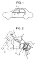
extrusion molding system 10 having those features,tiny holes 7 may be sealed with acoating 8 formed of a thermoplastic elastomer or resin, formed on the surface of the slightly foamedsolid rubber portion 3, by use of acoating unit 16 after thetiny holes 7 having the depth reaching thecore bar 4 are defined in part of the slightly foamedsolid rubber portion 3, within the U-shapedtrim 2, in such a way as to be arranged in line along the longitudinal direction of theweather strip 1 by use of theprickly gear 13. - Fig. 1 is a side view of an automobile with a weather strip attached thereto;
- Fig. 2 is a cross-sectional view of the weather strip for the automobile, taken on line Z - Z in Fig. 1;
- Fig. 3 is a cross-sectional view of a conventional weather strip for an automobile;
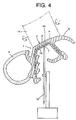
- Fig. 4 is a cross-sectional view showing an embodiment of a weather strip for an automobile according to the invention, and a prickly gear and so forth of an embodiment of a continuous extrusion molding system for molding the weather strip for the automobile, according to the invention;
- Fig. 5 is a side view of the embodiment of the continuous extrusion molding system for molding the weather strip for the automobile, according to the invention; and
- Fig. 6 is a side view showing another embodiment of a continuous extrusion molding system for molding the weather strip for the automobile, according to the invention.
-
- Figs. 1, 2, and 4 show an embodiment of a
weather strip 1 for an automobile, according to the invention. The same comprises aU-shaped trim 2 formed by embedding acore bar 4 in a slightly foamedsolid rubber portion 3 foamed to have a specific gravity of 0.8 to 1.2, and the slightly foamedsolid rubber portion 3 hastiny holes 7 having a depth reaching thecore bar 4, defined so as to be arranged in line along the longitudinal direction of theweather strip 1, in order to discharge gas evolved inside the slightly foamedsolid rubber portion 3 at the time of extrusion molding and vulvanization into the air. - The
weather strip 1 for the automobile, according to the embodiment, is attached to a flange 30 (or a flange at the rim of a door) at the rim of an opening of an automobile body, and a hollow seal portion which is asponge rubber portion 5 for elastically contacting a door (or a body panel), and alip portion 6 of the slightly foamedsolid rubber portion 3, for elastically contacting the body panel (or the door), are formed integrally with theU-shaped trim 2, which is part of the slightly foamedsolid rubber portion 3, fitted to theflange 30. In the figures, a door frame is denoted byreference numeral 31, and a door glass is denoted byreference numeral 32. - With the present embodiment, the
tiny holes 7 are defined in agroove bottom 3a of a U-like shape of theU-shaped trim 2. As thegroove bottom 3a is a part normally most prone to occurrence of avoid 21, gas can be discharged into the air by forming thetiny holes 7 therein, thereby preventing thevoid 21 from occurring. - Further, occurrence of the
void 21 will not be limited to the part described. Accordingly, thetiny holes 7 are formed as necessary in any parts of the slightly foamedsolid rubber portion 3, such as anouter part 3b of theU-shaped trim 2, both right side and left side parts thereof, and so forth, as targets for the formation of thetiny holes 7. - In the case where the
tiny holes 7 are defined in theouter part 3b visible from outside, thetiny holes 7 are sealed with acoating 8 formed of a thermoplastic elastomer or resin after gas is discharged through thetiny holes 7, thereby enhancing agreeableness in appearance. - Furthermore, the slightly foamed
solid rubber portion 3 of the weather strip has a specific gravity lowered to a suitable extent of a range of 0.8 to 1.2 by foaming, and consequently, reduction in weight is implemented without impairing mechanical strength required of the weather strip. - Figs. 4 and 5 show an embodiment of a continuous
extrusion molding system 10 for the weather strip for the automobile, according to the invention. The continuousextrusion molding system 10 is a system for continuously extrusion molding theweather strip 1 for the automobile, comprising the U-shapedtrim 2 formed by embedding thecore bar 4 in the slightly foamedsolid rubber portion 3, and is provided with aprickly gear 13, rotatable while pressed in contact with the weather strip being extruded, disposed so as to be adjacent to amouth piece 12 of anextruder 11. Thetiny holes 7 having the depth reaching thecore bar 4 are defined in the slightly foamedsolid rubber portion 3 by use of theprickly gear 13 in such a way as to be arranged in line along the longitudinal direction of theweather strip 1, thereby discharging gas evolved inside the slightly foamedsolid rubber portion 3 in the air. - In the case where the
tiny holes 7 are defined in theouter part 3b of the U-like shape of a part of the slightly foamedsolid rubber portion 3, agreeableness in appearance can be enhanced if thetiny holes 7 are covered with, and sealed by thecoating 8 formed of a thermoplastic elastomer or resin after gas is discharged. In this case, for example, thetiny holes 7 may be defined so as to be arranged in line immediately after theweather strip 1 is extruded out of themouth piece 12, and thereafter, thetiny holes 7 may be continuously coated with resin by use of a coating unit (another extruder, and so forth) 16 after vulcanization in avulcanizing furnace 15. - With the present embodiment, the
prickly gear 13 is disposed at a spot about 20 mm away from themouth piece 12, continuously forming thetiny holes 7 in thegroove bottom 3a of the U-like shape of the U-shapedtrim 2 so as to be arranged in line along the longitudinal direction of theweather strip 1. Further, anembossing roll 14 is rotatably attached to themouth piece 12 so as to be rolled along on the outer face of theU-shaped trim 2 for continuously cutting an embossed pattern thereon. Theweather strip 1 molded with thecontinuous extruding system 10 is sent out to thevulcanizing furnace 15 to be heated therein for vulcanization. - Since the
weather strip 1 molded with thecontinuous extruding system 10 is provided with thetiny holes 7 having the depth reaching thecore bar 4, defined in the slightly foamedsolid rubber portion 3, in the U-shapedtrim 2, so as to be arranged in line along the longitudinal direction of theweather strip 1, gas evolved inside the slightly foamedsolid rubber portion 3 due to heat at the time of extrusion molding and vulvanization can be discharged into the air. Accordingly, thevoid 21 can be prevented from occurring. - The
weather strip 1 passing through thevulcanizing furnace 15 may be at times fitted to theflange 30 of the automobile body after two legs of thecore bar 4 in a shape substantially resembling the letter U are bent so as to be parallel with each other as shown in Fig. 2. - In the first aspect of the invention, the
weather strip 1 for the automobile is provided with thetiny holes 7 having the depth reaching thecore bar 4, defined in the slightly foamedsolid rubber portion 3, and consequently, gas evolved inside the slightly foamedsolid rubber portion 3 at the time of extrusion molding and vulvanization can be discharged into the air, thereby preventing thevoid 21 from occurring to the boundary part between the slightly foamedsolid rubber portion 3 and thecore bar 4. Accordingly, it is possible to solve problems such as difficulty with fitting theweather strip 1 for the automobile to theflange 30, and occurrence of poor external appearance . - With the
weather strip 1 for the automobile, having those features, thetiny holes 7 are preferably sealed with acoating 8 formed of a thermoplastic elastomer or resin, so that deterioration of agreeableness in appearance does not occur. - The invention provides in its second aspect the continuous
extrusion molding system 10 for continuously extrusion molding the weather strip for the automobile, comprising theprickly gear 13, rotatable while pressed in contact with theweather strip 1 being extruded, and disposed so as to be adjacent to themouth piece 12 of theextruder 11, wherein a multitude of thetiny holes 7, having the depth reaching thecore bar 4, are defined in the slightly foamedsolid rubber portion 3, so that gas evolved inside the slightly foamedsolid rubber portion 3 can be discharged into the air. Accordingly, occurrence of thevoid 21 can be prevented, thereby solving the problems such as difficulty with fitting theweather strip 1 for the automobile to theflange 30, and occurrence of poor external appearance . - Further, with the continuous
extrusion molding system 10 having those features, wherein thetiny holes 7 formed in theouter part 3b of the slightly foamedsolid rubber portion 3 are sealed with acoating 8 formed of a thermoplastic elastomer or resin by use of acoating unit 16, deterioration of agreeableness in appearance of theweather strip 1 as molded can be prevented. The features disclosed in the foregoing description, in the claims and/or the accompanying drawings may, both separately and in any combination thereof, be material for realising the invention in diverse forms thereof.
Claims (5)
- A weather strip for an automobile comprising a U-shaped trim (2) formed by embedding a core bar (4) in a slightly foamed solid rubber portion (3), foamed so as to have a specific gravity of 0.8 to 1.2, wherein tiny holes (7) having a depth reaching the core bar (4) are defined in part of the slightly foamed solid rubber portion (3), within the U-shaped trim (2), in such a way as to be arranged in line along the longitudinal direction of the weather strip.
- A weather strip for an automobile comprising a U-shaped trim (2) formed by embedding a core bar (4) in a slightly foamed solid rubber portion (3), foamed so as to have a specific gravity of 0.8 to 1.2, wherein tiny holes (7) having a depth reaching the core bar (4) are defined in a groove bottom (3a) of a U-like shape of a part of the slightly foamed solid rubber portion (3), within the U-shaped trim (2), in such a way as to be arranged in line along the longitudinal direction of the weather strip.
- A weather strip for an automobile comprising a U-shaped trim (2) formed by embedding a core bar (4) in a slightly foamed solid rubber portion (3), foamed so as to have a specific gravity of 0.8 to 1.2, wherein tiny holes (7) having a depth reaching the core bar (4) are defined in an outer part (3b) of the slightly foamed solid rubber portion (3), and the tiny holes (7) are sealed with a coating (8) formed of a thermoplastic elastomer or resin.
- A continuous extrusion molding system for continuously extrusion molding a weather strip for an automobile, comprising a U-shaped trim (2) formed by embedding a core bar (4) in a slightly foamed solid rubber portion (3), comprising a prickly gear (13), rotatable while pressed in contact with the weather strip being extruded, and disposed so as to be adjacent to a mouth piece (12) of an extruder (11), wherein tiny holes (7) having a depth reaching the core bar (4) are defined in part of the slightly foamed solid rubber portion (3), within the U-shaped trim (2), in such a way as to be arranged in line along the longitudinal direction of the weather strip by use of the prickly gear (13).
- A continuous extrusion molding system for continuously extrusion molding a weather strip for an automobile, comprising a U-shaped trim (2) formed by embedding a core bar (4) in a slightly foamed solid rubber portion (3), comprising a prickly gear (13), rotatable while pressed in contact with the weather strip being extruded, and disposed so as to be adjacent to a mouth piece (12) of an extruder (11), wherein tiny holes (7) having a depth reaching the core bar (4) are defined in part of the slightly foamed solid rubber portion (3), within the U-shaped trim (2), in such a way as to be arranged in line along the longitudinal direction of the weather strip by use of the prickly gear (13), and thereafter, the tiny holes (7) are sealed with a coating (8) of a thermoplastic elastomer or resin, formed on the surface of the slightly foamed solid rubber portion (3) by use of a coating unit (16).
Applications Claiming Priority (4)
| Application Number | Priority Date | Filing Date | Title |
|---|---|---|---|
| JP2001201887 | 2001-07-03 | ||
| JP2001201887 | 2001-07-03 | ||
| JP2002071309 | 2002-03-15 | ||
| JP2002071309A JP3579835B2 (en) | 2001-07-03 | 2002-03-15 | Automotive weather strip and continuous extrusion equipment |
Publications (3)
| Publication Number | Publication Date |
|---|---|
| EP1273471A2 true EP1273471A2 (en) | 2003-01-08 |
| EP1273471A3 EP1273471A3 (en) | 2003-07-16 |
| EP1273471B1 EP1273471B1 (en) | 2012-08-01 |
Family
ID=26618036
Family Applications (1)
| Application Number | Title | Priority Date | Filing Date |
|---|---|---|---|
| EP02013757A Expired - Lifetime EP1273471B1 (en) | 2001-07-03 | 2002-06-20 | Wheather strip for automobile and continuous extrusion molding system for molding same |
Country Status (4)
| Country | Link |
|---|---|
| US (2) | US6686020B2 (en) |
| EP (1) | EP1273471B1 (en) |
| JP (1) | JP3579835B2 (en) |
| KR (1) | KR20030004108A (en) |
Cited By (2)
| Publication number | Priority date | Publication date | Assignee | Title |
|---|---|---|---|---|
| US9174519B2 (en) | 2011-10-18 | 2015-11-03 | Henniges Automotive Sealing Systems North America Inc. | Weatherstrip assembly having a variable length shim |
| CN109649293A (en) * | 2018-12-28 | 2019-04-19 | 萨固密(中国)投资有限公司 | Three-stage monodentate sealing strip |
Families Citing this family (19)
| Publication number | Priority date | Publication date | Assignee | Title |
|---|---|---|---|---|
| DE102004005257B4 (en) * | 2003-02-07 | 2005-09-15 | Toyoda Gosei Co., Ltd., Nishikasugai | weatherstrip |
| JP4168860B2 (en) * | 2003-07-11 | 2008-10-22 | 豊田合成株式会社 | Glass run |
| JP4726786B2 (en) * | 2003-09-17 | 2011-07-20 | 東海興業株式会社 | Long decorative member and manufacturing method thereof |
| CN100400321C (en) * | 2004-08-09 | 2008-07-09 | 丰田合成株式会社 | Weather strips |
| US20060086053A1 (en) * | 2004-10-27 | 2006-04-27 | Peter John Ellis | Lightweight glass-run channels |
| JP2007168571A (en) * | 2005-12-21 | 2007-07-05 | Nishikawa Rubber Co Ltd | Slightly foamed solid rubber weather strip |
| JP4752674B2 (en) | 2006-08-21 | 2011-08-17 | 豊田合成株式会社 | Weather strip manufacturing method |
| JP4973152B2 (en) * | 2006-11-28 | 2012-07-11 | 豊田合成株式会社 | Opening trim weather strip |
| US20080271739A1 (en) | 2007-05-03 | 2008-11-06 | 3M Innovative Properties Company | Maintenance-free respirator that has concave portions on opposing sides of mask top section |
| US9770611B2 (en) | 2007-05-03 | 2017-09-26 | 3M Innovative Properties Company | Maintenance-free anti-fog respirator |
| US20080271740A1 (en) * | 2007-05-03 | 2008-11-06 | 3M Innovative Properties Company | Maintenance-free flat-fold respirator that includes a graspable tab |
| US8205391B2 (en) * | 2007-09-20 | 2012-06-26 | Toyoda Gosei Co., Ltd. | Automobile weather strip |
| JP4577791B2 (en) * | 2007-12-28 | 2010-11-10 | 東海興業株式会社 | Molded product and manufacturing method thereof |
| JP2011183935A (en) * | 2010-03-09 | 2011-09-22 | Toyoda Gosei Co Ltd | Door weather strip |
| JP6022144B2 (en) * | 2010-04-01 | 2016-11-09 | 東海興業株式会社 | Glass run channel, its assembly and manufacturing method |
| JP5990524B2 (en) | 2010-10-18 | 2016-09-14 | バイオセプティブ,インコーポレイテッド | Apparatus and method for inserting an instrument or drug into a body cavity |
| RU2642340C2 (en) | 2013-07-15 | 2018-01-24 | 3М Инновейтив Пропертиз Компани | Respirator with optically active exhalation valve |
| CA2927636A1 (en) * | 2014-02-07 | 2015-08-13 | Fca Fiat Chrysler Automoveis Brasil Ltda. | Vertical sealing arrangement between doors without side pillars |
| DE102014118029A1 (en) * | 2014-12-05 | 2016-06-09 | Cooper Standard GmbH | PROFILE STRUCTURE AND METHOD FOR MANUFACTURING A PROFILE STRUCTURE |
Family Cites Families (6)
| Publication number | Priority date | Publication date | Assignee | Title |
|---|---|---|---|---|
| US3817671A (en) * | 1970-09-01 | 1974-06-18 | J Lemelson | Apparatus for forming sheet material |
| AR202806A1 (en) * | 1973-08-22 | 1975-07-24 | Romanillos F | POLIADITION PROCESS AND APPARATUS FOR ITS REALIZATION |
| JPH06286478A (en) * | 1993-03-31 | 1994-10-11 | Toyoda Gosei Co Ltd | Manufacture of weather strip with built-in core |
| JP2854236B2 (en) * | 1993-12-28 | 1999-02-03 | ワイケイケイ株式会社 | Method and apparatus for manufacturing surface fastener |
| JPH08142672A (en) * | 1994-11-15 | 1996-06-04 | Nishikawa Rubber Co Ltd | Door opening weather strip |
| JP3417333B2 (en) * | 1999-03-16 | 2003-06-16 | 豊田合成株式会社 | Weather strip |
-
2002
- 2002-03-15 JP JP2002071309A patent/JP3579835B2/en not_active Expired - Lifetime
- 2002-06-20 US US10/175,650 patent/US6686020B2/en not_active Expired - Lifetime
- 2002-06-20 EP EP02013757A patent/EP1273471B1/en not_active Expired - Lifetime
- 2002-07-02 KR KR1020020037853A patent/KR20030004108A/en not_active Withdrawn
-
2003
- 2003-11-19 US US10/717,261 patent/US7036826B2/en not_active Expired - Fee Related
Non-Patent Citations (1)
| Title |
|---|
| None |
Cited By (2)
| Publication number | Priority date | Publication date | Assignee | Title |
|---|---|---|---|---|
| US9174519B2 (en) | 2011-10-18 | 2015-11-03 | Henniges Automotive Sealing Systems North America Inc. | Weatherstrip assembly having a variable length shim |
| CN109649293A (en) * | 2018-12-28 | 2019-04-19 | 萨固密(中国)投资有限公司 | Three-stage monodentate sealing strip |
Also Published As
| Publication number | Publication date |
|---|---|
| US20030008103A1 (en) | 2003-01-09 |
| KR20030004108A (en) | 2003-01-14 |
| JP2003080582A (en) | 2003-03-19 |
| EP1273471B1 (en) | 2012-08-01 |
| US6686020B2 (en) | 2004-02-03 |
| US7036826B2 (en) | 2006-05-02 |
| EP1273471A3 (en) | 2003-07-16 |
| JP3579835B2 (en) | 2004-10-20 |
| US20040104543A1 (en) | 2004-06-03 |
Similar Documents
| Publication | Publication Date | Title |
|---|---|---|
| US6686020B2 (en) | Weather strip for automobile and continuous extrusion molding system for molding same | |
| EP0325830B1 (en) | Cohesive bonding process for forming a laminate of a wear resistant thermoplastic and a weather resistant rubber | |
| EP1040950B1 (en) | Seals for vehicles | |
| JP4344809B2 (en) | Door weather strip | |
| US20060137255A1 (en) | Weather strip for vehicle | |
| JP4752674B2 (en) | Weather strip manufacturing method | |
| JP2000025462A (en) | Glass run | |
| JP4193116B2 (en) | Automotive beltline mall | |
| CN110171280A (en) | Weather strip for automobile | |
| JP2007062532A (en) | Automobile door weather strip | |
| JP2009001143A (en) | Glass run for automobile | |
| JP2003165340A (en) | Glass run for automobile | |
| CN100400321C (en) | Weather strips | |
| JP3708612B2 (en) | Method and apparatus for producing rubber molded article for anti-noise weather strip | |
| JP2005329728A (en) | Glass run for automobile | |
| JP4228711B2 (en) | Weather strip | |
| US6898916B2 (en) | Weather strip | |
| JP2002187431A (en) | Weather strip and manufacturing method thereof | |
| JP2006123693A (en) | Glass run for automobile | |
| JP2001018658A (en) | Automotive weather strip | |
| JP2010228725A (en) | Glass run for automobile | |
| JP2006248255A (en) | Glass run | |
| JP2006096225A (en) | Glass run for automobile | |
| JP2006015776A (en) | Glass run | |
| JP2000118324A (en) | Weather strip for seal hood and method of manufacturing the same |
Legal Events
| Date | Code | Title | Description |
|---|---|---|---|
| PUAI | Public reference made under article 153(3) epc to a published international application that has entered the european phase |
Free format text: ORIGINAL CODE: 0009012 |
|
| AK | Designated contracting states |
Kind code of ref document: A2 Designated state(s): AT BE CH CY DE DK ES FI FR GB GR IE IT LI LU MC NL PT SE TR |
|
| AX | Request for extension of the european patent |
Free format text: AL;LT;LV;MK;RO;SI |
|
| PUAL | Search report despatched |
Free format text: ORIGINAL CODE: 0009013 |
|
| RIC1 | Information provided on ipc code assigned before grant |
Ipc: 7B 29C 44/56 B Ipc: 7B 29C 69/00 B Ipc: 7B 29C 47/02 B Ipc: 7B 60J 10/00 A |
|
| AK | Designated contracting states |
Designated state(s): AT BE CH CY DE DK ES FI FR GB GR IE IT LI LU MC NL PT SE TR |
|
| AX | Request for extension of the european patent |
Extension state: AL LT LV MK RO SI |
|
| 17P | Request for examination filed |
Effective date: 20031120 |
|
| AKX | Designation fees paid |
Designated state(s): DE FR GB |
|
| 17Q | First examination report despatched |
Effective date: 20090717 |
|
| GRAP | Despatch of communication of intention to grant a patent |
Free format text: ORIGINAL CODE: EPIDOSNIGR1 |
|
| GRAS | Grant fee paid |
Free format text: ORIGINAL CODE: EPIDOSNIGR3 |
|
| GRAA | (expected) grant |
Free format text: ORIGINAL CODE: 0009210 |
|
| AK | Designated contracting states |
Kind code of ref document: B1 Designated state(s): DE FR GB |
|
| REG | Reference to a national code |
Ref country code: GB Ref legal event code: FG4D |
|
| REG | Reference to a national code |
Ref country code: DE Ref legal event code: R096 Ref document number: 60243400 Country of ref document: DE Effective date: 20120927 |
|
| PLBE | No opposition filed within time limit |
Free format text: ORIGINAL CODE: 0009261 |
|
| STAA | Information on the status of an ep patent application or granted ep patent |
Free format text: STATUS: NO OPPOSITION FILED WITHIN TIME LIMIT |
|
| 26N | No opposition filed |
Effective date: 20130503 |
|
| PGFP | Annual fee paid to national office [announced via postgrant information from national office to epo] |
Ref country code: DE Payment date: 20130612 Year of fee payment: 12 |
|
| REG | Reference to a national code |
Ref country code: DE Ref legal event code: R097 Ref document number: 60243400 Country of ref document: DE Effective date: 20130503 |
|
| PGFP | Annual fee paid to national office [announced via postgrant information from national office to epo] |
Ref country code: FR Payment date: 20130624 Year of fee payment: 12 |
|
| GBPC | Gb: european patent ceased through non-payment of renewal fee |
Effective date: 20130620 |
|
| PG25 | Lapsed in a contracting state [announced via postgrant information from national office to epo] |
Ref country code: GB Free format text: LAPSE BECAUSE OF NON-PAYMENT OF DUE FEES Effective date: 20130620 |
|
| REG | Reference to a national code |
Ref country code: DE Ref legal event code: R119 Ref document number: 60243400 Country of ref document: DE |
|
| REG | Reference to a national code |
Ref country code: FR Ref legal event code: ST Effective date: 20150227 |
|
| REG | Reference to a national code |
Ref country code: DE Ref legal event code: R119 Ref document number: 60243400 Country of ref document: DE Effective date: 20150101 |
|
| PG25 | Lapsed in a contracting state [announced via postgrant information from national office to epo] |
Ref country code: DE Free format text: LAPSE BECAUSE OF NON-PAYMENT OF DUE FEES Effective date: 20150101 |
|
| PG25 | Lapsed in a contracting state [announced via postgrant information from national office to epo] |
Ref country code: FR Free format text: LAPSE BECAUSE OF NON-PAYMENT OF DUE FEES Effective date: 20140630 |