BACKGROUND OF THE INVENTION
1. Field of the Invention
The present invention relates to an electrode producing
method. More particularly, the present invention relates to
an electrode producing method in which metal bars for an
electrode can be welded together efficiently.
2. Description Related to the Prior Art
A camera has an electronic flash device, which includes
a flash discharge tube. The flash discharge tube has a glass
vessel and xenon gas enclosed therein. Pin-shaped electrodes
are positioned through end portions of the glass vessel. For
flash emitting operation, a main capacitor is discharged, so
that charge passes between the pin-shaped electrodes to emit
flash light instantaneously.
Each of the pin-shaped electrodes includes an electrode
core and a lead connected therewith. The electrode core is
contained in the glass vessel, and formed from tungsten (W).
The lead protrudes externally from the glass vessel, and is
formed from nickel (Ni) or manganese-nickel (Mn-Ni). To
obtain the pin-shaped electrode, an end of a tungsten bar is
welded on to an end of a nickel lead. Specifically, an
electric current is caused to flow between the tungsten bar
and the nickel lead while the end of the tungsten bar is kept
butting on that of the nickel lead. The end of the nickel
lead is melted, and wraps the end of the tungsten bar for the
welding, because the nickel lead has a considerably low
melting point. A ball-shaped melted portion is formed at the
end of the nickel lead being welded, and is used for
positioning the pin-shaped electrode in the glass vessel.
A ring-shaped cathode part is attached to the tungsten
bar of the pin-shaped electrode being a cathode, and formed
from sintered metal including cesium compound, and operates
for raising efficiency in emission of electron. The ring-shaped
cathode part has a central hole, in which the pin-shaped
electrode is inserted. The ring-shaped cathode part
is depressed and deformed, and attached to the pin-shaped
electrode by caulking. For the purpose of tightening the
caulking, a surface of the tungsten bar of the pin-shaped
electrode is provided with a random pattern of minute
recesses or scratches.
The ball-shaped melted portion formed between the
tungsten bar and the nickel lead is required to have a
regularized shape and size for the purpose of positioning the
pin-shaped electrode in the glass vessel. However, the shape
of the ball-shaped melted portion changes according to
various conditions of welding, and is difficult to have a
regularized common shape.
In the conventional technique for the pin-shaped
electrode, the random pattern of recesses or scratches is
formed by cutting, scraping or abrading or in other manners
at the time of manufacturing the tungsten bar. However, the
number of steps of creating the random pattern is
considerably great. So the cost for producing the pin-shaped
electrode cannot be reduced because of the complicated
processes.
SUMMARY OF THE INVENTION
In view of the foregoing problems, an object of the
present invention is to provide an electrode producing method
in which metal bars for an electrode can be welded together
efficiently, to produce the electrode at a low cost.
In order to achieve the above and other objects and
advantages of this invention, an electrode producing method
of producing a pin-shaped electrode for a flash discharge
tube is provided, the pin-shaped electrode including a first
bar of metal having a first end portion, and a second bar of
metal having a second end portion connected with the first
end portion. In the electrode producing method, the first
and second bars are retained by use of respectively first and
second chuck mechanisms with the first and second end
portions opposed to one another. The first and second end
portions are pushed on one another by moving at least one of
the first and second chuck mechanisms. While the first and
second end portions are pushed on one another, the first and
second chuck mechanisms are supplied with electric current,
so as to weld the first and second bars together therewith by
resistance welding.
In the welding step, the second end portion is melted to
form a ball-shaped melted portion, the ball-shaped melted
portion is secured by wrapping the first end portion.
The flash discharge tube includes a vessel having
discharge gas enclosed therein. A second pin-shaped
electrode is inserted through and secured to the vessel. The
pin-shaped electrode is inserted through the vessel, the
second bar extends externally from the vessel, the first bar
is disposed in the vessel, and opposed to the second pin-shaped
electrode. The ball-shaped melted portion is
positioned on an outer surface of the vessel.
Furthermore, a protruding amount of the first bar from
the first chuck mechanism is adjusted before the second chuck
mechanism supplies the second bar.
The ball-shaped melted portion after welding has a
greater diameter than a thickness thereof as viewed in an
axial direction of the pin-shaped electrode.
The first and second chuck mechanisms include first and
second two-way chucks, the first two-way chuck squeezes the
first bar in a first squeezing direction, the second two-way
chuck squeezes the second bar in a second squeezing
direction, the first and second squeezing directions are
substantially perpendicular to one another.
The first bar has a diameter Dw, and the protruding
amount of the first bar from the first chuck mechanism is
from 0.6·Dw to 1.5·Dw.
The first bar includes tungsten.
The pin-shaped electrode is a pin-shaped cathode, and
further includes a ring-shaped cathode part secured to the
first bar. Furthermore, a surface of the first bar is
subjected to surface processing. The cathode part is secured
to the first bar after the surface processing.
According to another aspect of the invention, an
electrode producing method of producing a pin-shaped
electrode for a flash discharge tube is provided, the pin-shaped
electrode including a first bar of metal and a ring-shaped
cathode part, secured to the first bar, for raising
efficiency in emitting electron. In the electrode producing
method, a recess is formed in the first bar by applying laser
light thereto. The cathode part is secured to the recess.
Furthermore, gas is blown over the first bar during the
recess forming step, to blow away metal dust created by
forming the recess.
The first bar has a first end portion disposed on a
farther side from the cathode part. The pin-shaped electrode
further includes a second bar of metal having a second end
portion connected with the first end portion. Furthermore,
the second bar is connected with the first bar before the
recess forming step.
The cathode part has a size Lc in an axial direction of
the pin-shaped electrode, and the recess has a width from
0.1·Lc to 1.5·Lc in the axial direction.
The first bar has a diameter Dw, and the recess has a
depth from 0.03·Dw to 0.4·Dw.
The cathode part includes cesium.
According to still another aspect of the invention, the
first bar is provided with surface roughness by subjecting
the first bar to sandblast processing. The cathode part is
secured to the first bar after the sandblast processing.
Furthermore, the cathode part is pressurized and
deformed, to attach the cathode part to the first bar.
The first bar has a first end portion disposed on a
farther side from the cathode part. The pin-shaped electrode
further includes a second bar of metal having a second end
portion connected with the first end portion. Furthermore,
a step of connecting the second bar with the first bar before
the sandblast processing.
Consequently, the metal bars for an electrode can be
welded together efficiently, to produce the electrode at a
low cost.
BRIEF DESCRIPTION OF THE DRAWINGS
The above objects and advantages of the present
invention will become more apparent from the following
detailed description when read in connection with the
accompanying drawings, in which:
DETAILED DESCRIPTION OF THE PREFERRED
EMBODIMENT(S) OF THE PRESENT INVENTION
In Figs. 1 and 2, a flash discharge tube 2 produced
according to the present invention is illustrated. The flash
discharge tube 2 includes a vessel 3, and a pin-shaped
cathode 6 and a pin-shaped anode 7 as two electrodes. The
vessel 3 is formed in a tubular shape, is transparent, and is
made of glass. Openings 4 and 5 are formed in ends of the
vessel 3. The pin-shaped cathode and anode 6 and 7 are
inserted in respectively the openings 4 and 5. A ring-shaped
cathode part 8 is attached to the pin-shaped cathode 6.
Glass beads 9 and 10 are fitted in the openings 4 and 5 in a
tight manner. Xenon gas as inert gas is filled in the vessel
3.
The pin-shaped cathode 6 includes a cathode core 12 as
electrode core, and a lead 13. The cathode core 12 is
contained in the vessel 3. The lead 13 protrudes externally
from the vessel 3, and is used for wiring to a printed
circuit board. A ball-shaped melted portion 14 is formed by
welding between the cathode core 12 and the lead 13.
The cathode core 12 is formed from tungsten (W) in a bar
shape. A recess or groove 20 is formed in the cathode core
12 for attaching the ring-shaped cathode part 8. The lead 13
is formed from nickel (Ni), and has a diameter equal to or
greater than a diameter of the cathode core 12. The
ball-shaped melted portion 14 is formed by partially melting
the lead 13 to cover an end of the cathode core 12 because of
welding between the cathode core 12 and the lead 13.
The cathode core 12 may be formed materials other than
tungsten. Examples of materials for the cathode core 12 are
alloy of nickel cobalt and iron, alloy of nickel and iron,
and alloy of molybdenum. The lead 13 may be formed materials
other than nickel. Examples of materials for the lead 13 are
manganese-nickel (Mn-Ni), alloy of cobalt, nickel and iron,
alloy of nickel and iron, and alloy of molybdenum. The
pin-shaped anode 7 includes an anode core 16 as electrode
core, a lead 17, and a ball-shaped melted portion 18 all
similar to the pin-shaped cathode 6. The anode core 16 has
a length different from that of the cathode core 12. Except
for this, the pin-shaped anode 7 is produced from the same
material and in the same manner as the pin-shaped cathode
6.
The glass beads 9 and 10 are formed in a ring shape.
Holes 9a and 10a are formed in the glass beads 9 and 10 for
insertion of the cathode core 12 and the anode core 16 of the
pin-shaped cathode and anode 6 and 7. The glass beads 9 and
10, after insertion of the cathode core 12 and the anode core
16, are heated by a heater, and welded on to the cathode core
12 and the anode core 16. Then the glass beads 9 and 10 are
inserted in the openings 4 and 5 of the vessel 3, heated and
melted by a heater, to close and seal the vessel 3 tightly.
The ring-shaped cathode part 8 includes components of
metal and a cesium compound. At first, powder of the metal
is formed in a ring shape, and sintered. The cesium compound
is added to this, and processed. In operation, the
ring-shaped cathode part 8 keeps efficiency high in emitting
electron during electric discharge. To fix the ring-shaped
cathode part 8, the ring-shaped cathode part 8 is positioned
at the recess 20 of the cathode core 12, and then depressed
and deformed by caulking for tight attachment.
In Fig. 3, a line for producing the pin-shaped cathode
6 is schematically illustrated. The producing line is
constituted by a welding process and a recess forming
process. In the welding process, a tungsten bar 22 as the
cathode core 12 is welded on to a nickel bar 23 as the lead
13, to obtain the pin-shaped cathode 6. In the recess
forming process, the recess 20 is formed in the cathode core
12 of the pin-shaped cathode 6. For the welding process, the
line includes an indexing table 24, and first, second, third,
fourth, fifth, sixth, seventh and eighth stations 25, 26, 27,
28, 29, 30, 31 and 32. The indexing table 24 rotates
stepwise by a unit angle of 45 degrees. The eight stations
25-32 are disposed where each pallet in the indexing table 24
is stopped. Various devices are disposed in the eight
stations 25-32.
There are eight chuck mechanisms 34 or two-way chucks,
disposed on the indexing table 24, to squeeze the tungsten
bar 22. Each of the chuck mechanisms 34 includes two jaws or
arms 35, and a shifter for moving the jaws 35 between a first
position for squeezing the tungsten bar 22 and a second
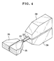
position for releasing the tungsten bar 22. In Fig. 4,
grooves or recesses are formed in contact walls of the jaws
35, have shapes for being fitted on the outer surface of the
tungsten bar 22. The recesses make it possible to squeeze
the tungsten bar 22 with high precision. Examples of the
shifter are a solenoid, cam mechanism and the like. The
chuck mechanisms 34 squeeze with such force that the tungsten
bar 22 does not offset in the axial direction, and that no
flaw or defect will remain in the tungsten bar 22 being
captured.
There are eight chuck mechanisms 37 or two-way chucks,
disposed on the indexing table 24, opposed to respectively
the chuck mechanisms 34, to squeeze the nickel bar 23. Each
of the chuck mechanisms 37 includes two jaws or arms 38, and
a shifter for moving the jaws 38 between a first position for
squeezing the nickel bar 23 and a second position for
releasing the nickel bar 23. Grooves or recesses are formed
in contact walls of the jaws 38, have shapes for being fitted
on the outer surface of the nickel bar 23. The recesses make
it possible to squeeze the nickel bar 23 with high precision.
Examples of the shifter are a solenoid, cam mechanism and the
like. The chuck mechanisms 37 squeeze with such force that
the nickel bar 23 does not offset in the axial direction, and
that no flaw or defect will remain in the nickel bar 23 being
captured.
In Fig. 4, the jaws 35 of the chuck mechanism 34 are
movable in a squeezing direction being perpendicular to that
in which the jaws 38 of the chuck mechanisms 37 are movable.
This is advantageous because the shifters for the chuck
mechanisms 34 and 37 can be disposed away from one another,
so as to reduce an overall size of the indexing table 24.
Also, precision in the concentricity between the tungsten bar
22 and the nickel bar 23 can be high. Furthermore, the chuck
mechanisms 34 and 37 constitute welding electrodes, included
in a resistance welding device, for connection with the
tungsten bar 22 and the nickel bar 23 being squeezed.
Examples of the materials for the chuck mechanisms 34 and 37
include chromium copper (Cu-Cr), tungsten copper (Cu-W),
superhard material and the like, and a combination of at
least two of those, for the purpose of good electrical
conductivity.
A tungsten bar supply device 40 is disposed in the first
station 25 on the periphery of the indexing table 24, and
includes a part feeder, and a pick-&-placement mechanism or
picking mechanism. The part feeder aligns the tungsten bar
22 produced by a separate manufacturing line. The pick-&-placement
mechanism picks the tungsten bar 22 from the part
feeder individually, and sends the tungsten bar 22 to a space
between the jaws 35 of the chuck mechanism 34.
A protrusion adjusting device 42 is disposed at the
second station 26, for adjusting a length Ls at which the
tungsten bar 22 protrudes from an end of the chuck mechanism
34. For the operation of the protrusion adjusting device 42,
the length Ls is predetermined and stored. Before the
protrusion adjusting device 42 is actuated, the tungsten bar
supply device 40 causes the chuck mechanism 34 in such a
manner that the tungsten bar 22 protrudes from the chuck
mechanism 34 at a protruding amount sufficiently greater than
the length Ls. Then the protrusion adjusting device 42 is
controlled to slide the tungsten bar 22 in a direction toward
the inside of the chuck mechanism 34, to reduce the
protruding amount to the length Ls.
A nickel bar supply device 44 is disposed in the third
station 27. At first, nickel wire with a continuous length
and a constant width is produced, wound about a reel, and set
in the nickel bar supply device 44. The nickel bar supply
device 44 draws the nickel wire from the reel, and uncurls
the nickel wire by use of a frictional roller or the like.
Then the nickel wire is wiped with solvent and non-woven
cloth or other fibrous wiping material, to remove dust,
powdery dirt, oil component and the like. After this, the
nickel bar 23 is produced by cutting the nickel wire at a
predetermined length. The nickel bar 23 is obtained, is
transferred to the chuck mechanism 37 by a pick-&-placement
mechanism, and is squeezed by the jaws 38. In Fig. 5A, ends
of the tungsten bar 22 and the nickel bar 23 are opposed to
one another.
A butting device 46 is disposed at the fourth station
28, and operates to shift the chuck mechanism 37 toward the
chuck mechanism 34. In Fig. 5B, an end of the nickel bar 23
is advanced to butt on an end of the tungsten bar 22. A
spring is incorporated in the butting device 46, and exerts
normally constant force to press the nickel bar 23 against
the tungsten bar 22.
A resistance welding device 49 is disposed at the fifth
station 29. The resistance welding device 49 causes a
current to flow between the chuck mechanisms 34 and 37. In
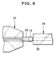
Fig. 6, the tungsten bar 22 and the nickel bar 23 are heated
because of the current and pressure. The end of the nickel
bar 23 is melted to wrap an end of the tungsten bar 22 so as
to weld the tungsten bar 22 and the nickel bar 23 to each
other. Note that the current flows in a direction from the
chuck mechanism 34 to the chuck mechanism 37 for the purpose
of generating heat according to the Peltier effect.
In the sixth station 30, the nickel bar 23 is released
from being squeezed in the chuck mechanism 37. The chuck
mechanism 37 comes away from the chuck mechanism 34. In the
seventh station 31, a pick-&-placement device 51 is disposed,
for receiving the pin-shaped cathode 6 from the chuck
mechanism 34, to supply the pin-shaped cathode 6 to a station
for the recess forming process. Note that, if an alarm
signal is generated in the resistance welding device 49 or
other devices at the time of the welding, the pin-shaped
cathode 6 is fed to the eighth station 32 without moving to
a region for the recess forming process. In the eighth
station 32, the chuck mechanism 34 is opened to eliminate the
pin-shaped cathode 6 determined unacceptable, for collection
of failing electrodes.
For the recess forming process, there are an indexing
table 54 and first, second, third, fourth, fifth and sixth
stations 55, 56, 57, 58, 59 and 60. The indexing table 54
has a smaller diameter than that of the indexing table 24,
and rotates stepwise by a unit angle of 60 degrees. The six
stations 55-60 are disposed where each pallet in the indexing
table 54 is stopped.
There are six electrode chucks 62, disposed on the upper
face of the indexing table 54, for squeezing the lead 13 of
the pin-shaped cathode 6, namely the nickel bar 23 after
welding. The electrode chucks 62 include a pair of jaws or
arms, and a shifter. The jaws squeeze the lead 13. The
shifter moves the jaws between a first position for grasping
the lead 13 and a second position for releasing the lead 13.
An example of the shifter includes a solenoid, cam mechanism
or the like.
At the first station 55 on the periphery of the indexing
table 54, the pick-&-placement device 51 supplies the
pin-shaped cathode 6 from the seventh station 31 of the
welding process. The pin-shaped cathode 6 is squeezed by the
electrode chuck 62. An electrode positioning device 64 is
disposed at the second station 56, and adjusts a position of
the pin-shaped cathode 6 nipped by the electrode chuck 62.
There are a laser processing device 66 and a gas
ejecting device 67 disposed at the third station 57. The
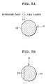
laser processing device 66 consists of a laser system of YAG
(yttrium aluminum garnet) laser, and as illustrated in Fig.
7A, emits laser light toward the cathode core 12 of the
pin-shaped cathode 6, so as to form the recess 20. See Fig.
7B. The gas ejecting device 67 ejects nitrogen gas toward
the pin-shaped cathode 6 while the laser light forms the
recess 20, to blow away dust of melted tungsten from the
pin-shaped cathode 6 to eliminate residual dust therefrom.
A shape inspecting device 69 is disposed at the fourth
station 58. The shape inspecting device 69 includes a video
camera unit and a control unit. The video camera unit picks
up an image of the pin-shaped cathode 6 to obtain image data.
The control unit stores reference data, compares the image
data from the video camera unit with the reference data, to
determine a size of the recess 20, or acceptability of a
shape of the recess 20.
In the fifth station 59, the electrode chuck 62 is
opened, from which the pin-shaped cathode 6 is unloaded. A
product receptacle or container 71 is disposed at the fifth
station 59, and receives the pin-shaped cathode 6, and
transfers the same to a succeeding line for producing a flash
discharge tube. If the pin-shaped cathode 6 is determined
unacceptable in the shape inspecting device 69 at the fourth
station 58, the pin-shaped cathode 6 moves past the fifth
station 59 without unloading from the electrode chuck 62.
When the pin-shaped cathode 6 reaches the sixth station 60,
the pin-shaped cathode 6 is removed from the electrode chuck
62 at the sixth station 60. An failure product receptacle or
container 72 at the sixth station 60 receives the pin-shaped
cathode 6, and collects electrodes created one after another.
Note that a producing line for the pin-shaped anode 7 is the
same as that for the pin-shaped cathode 6 except for lack of
partial elements including the seventh station 31 and the
recess forming process. For details of the producing line
for the pin-shaped anode 7, see the description of that for
the pin-shaped cathode 6.
The pin-shaped cathode 6 and the pin-shaped anode 7 are
transferred to a line for producing a flash discharge tube.
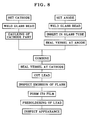
In Fig. 8, a flow of steps is illustrated, according to which
the producing line produces the flash discharge tube. In
Fig. 9A, a heating support plate 75 or heater jig is
illustrated, and includes hundreds of retention holes 76.
The pin-shaped cathode 6 supplied to the producing line is
inserted into each of the retention holes 76 by advancing the
lead 13. The heating support plate 75 has a plate shape, is
formed from carbon, and includes the retention holes 76
aligned regularly. The hundreds of the pin-shaped cathodes
6 are treated at the same time in the heating support plate
75.
While the pin-shaped cathode 6 is supported on the
heating support plate 75, the glass bead 9 is supplied so
that the cathode core 12 of the pin-shaped cathode 6 is
inserted in the glass bead 9. The pin-shaped cathode 6, the
glass bead 9 together with the heating support plate 75 are
supplied with heat by a heater. Therefore, the glass bead 9
is melted and welded on to the pin-shaped cathode 6.
In Fig. 9B, the cathode core 12 of the pin-shaped
cathode 6 is inserted in the ring-shaped cathode part 8,
which is depressed and deformed according to a technique of
caulking, and is attached fixedly to the pin-shaped cathode
6. An example of the caulking method and device used herein
is disclosed in JP-A 6-230456.
In a manner similar to the pin-shaped cathode 6, the
pin-shaped anode 7 is set on the heating support plate 75.
The glass bead 10 is melted and welded. Then the vessel 3 is
supplied to the pin-shaped anode 7, receives insertion of the
pin-shaped anode 7, and is heated by the heater again. Then
the glass bead 10 and the vessel 3 are melted and welded
together, to fix the pin-shaped anode 7 on the vessel 3.
Then the pin-shaped cathode 6 is inserted in the vessel
3 supported in the heating support plate 75. The portion of
the vessel 3 with the pin-shaped cathode 6 is held by the
heating support plate 75, and is heated. See Fig. 10. The
heat is applied in a condition filled with xenon gas. The
vessel 3 is closed and sealed. At the same time, xenon gas
is enclosed in the flash discharge tube 2. After completing
the flash discharge tube, the lead 13 of the pin-shaped
cathode 6 and the lead 17 of the pin-shaped anode 7 are cut
down at a predetermined length. The flash discharge tube is
subjected to inspection of flash emission. If the flash
discharge tube 2 is determined acceptable after the
inspection, then the vessel 3 is coated with a film of ITO
(indium tin oxide). Appearance of the flash discharge tube
2 is inspected, before the flash discharge tube 2 is shipped
out.
EXAMPLES
In Fig. 11, the cathode core 12 of the pin-shaped
cathode 6 has a diameter Dw of 0.6 mm, and a length Lw of 4.5
mm. The lead 13 has a diameter Dn of 0.8 mm. The pin-shaped
cathode 6 has a total length Ld of 19.5 mm. The ball-shaped
melted portion 14 has a diameter Db of 0.95-1.13 mm, and a
size Lb that is preferably 0.8 mm in the axial direction of
the electrode. The pin-shaped anode 7 is different from the
pin-shaped cathode 6 in that the anode core 16 has a length
of 3.5 mm and the pin-shaped anode 7 has a total length of
18.5 mm. Except for those, the pin-shaped anode 7 has the
same sizes as those of the pin-shaped cathode 6.
In the pin-shaped cathode 6, the size Lb of the
ball-shaped melted portion 14 is an important factor in view
of maintaining quality of the flash discharge tube 2. The
ball-shaped melted portion 14 is used for positioning the
pin-shaped cathode 6 on the vessel 3. Should the size Lb be
too great, the length Lw of the cathode core 12 will be too
small. Should the size Lb be too small, the length Lw of the
cathode core 12 will be too great. So a distance between the
cathode core 12 and the anode core 16 is likely to be uneven.
An arc length of the electric discharge may change.
Consequently, it is preferable that the ball-shaped melted
portion 14 has a shape of an ellipsoid like a pumpkin fruit
defined by compressing a sphere in one direction, in
comparison with a shape of an ellipsoid like a rugby ball
defined by extending a sphere in one direction. In other
words, the ball-shaped melted portion 14 should meet the
condition of Lb < Db instead of Lb > Db.
A great number of electrodes 6 were produced in
combination of the tungsten bar 22 and the nickel bar 23 by
changing conditions of welding for obtaining optimum
condition to manufacture the ball-shaped melted portion 14
regularly at the above described size. As a result, it was
observed that the shape of the ball-shaped melted portion 14
depended on various factors, that were the protruding amount
Ls of the tungsten bar 22 from the end of the chuck mechanism
34, the force of the tungsten bar 22 to push the nickel bar
23, the voltage applied for the resistance welding, and the
time of applying the voltage.
According to the above results of the observation, the
tungsten bar 22 and the nickel bar 23 were welded to one
another in such a manner as to maintain the ball diameter Db
at approximately 1 mm by changing the protruding amount Ls of
the tungsten bar 22 and the voltage. Then the length Lw of
the electrode, the ball diameter Db and the ball size Lb were
measured, and indicated in the graph of Fig. 12. Note that
ten samples of electrodes were produced experimentally for
measurement. Values indicated in Fig. 12 were averages of
the ten. In Fig. 13, a pattern of applying voltage is
illustrated. The tungsten bar 22 and the nickel bar 23 were
preheated at a preheating voltage level P3 for 40 msec, and
heated at a heating voltage level P4 for 55 msec for a main
process of welding by melting the nickel bar 23.
According to the data in Fig. 12, it was found that ball
diameter Db could be kept constant by changing the voltage
even with changes in the protruding amount Ls. Also, the
ball size Lb became the greater according to an increase of
the protruding amount Ls. The electrode core length Lw
became the smaller in inverse proportion to the increase of
the protruding amount Ls. It is supposed that reason for
this result was that portions of the tungsten bar 22 and the
nickel bar 23 other than butting portions of the tungsten bar
22 and the nickel bar 23 were heated by a flow of a current.
It was found that the protruding amount Ls of the tungsten
bar 22 was preferably in a range from 0.8·Dw to 1.5·Dw, and
preferably 0.7 mm or so.
Furthermore, the experiment was conducted with other
samples. To check a relationship between the shape of the
ball-shaped melted portion 14 and the welding time, the
protruding amount Ls of the tungsten bar 22 was uniquely
determined 0.7 mm. The welding time was determined 10 msec
and 75 msec. The length Lw of the electrode, the ball
diameter Db and the ball size Lb were measured. Note that
ten samples of electrodes were produced experimentally for
measurement. Values indicated in Fig. 14 were averages of
the ten. In Fig. 15, a pattern of applying voltage is
illustrated. The tungsten bar 22 and the nickel bar 23 were
heated at a heating voltage level P4 for T4 (msec) for a main
welding by melting the nickel bar 23.
As a result of the experiment, the nickel bar 23 was
melted only when the voltage P3 was set at nearly 1.5 volts
or higher and when the welding time was 10 msec. When the
welding time was 75 msec, the nickel bar 23 was melted when
the voltage was as low as 0.7 volt. If the welding time is
short, voltage to be applied must be set high. In the
experiment in which the voltage was high, portions of the
tungsten bar 22 and the nickel bar 23 different from the
butting portions was heated remarkably to cause the
ball-shaped melted portion 14 to have a shape of an ellipsoid
like a rugby ball defined by extending a sphere in one
direction. When the welding time was long, the ball-shaped
melted portion 14 came to have a shape of an ellipsoid like
a pumpkin fruit defined by compressing a sphere in one
direction. However, problems are likely to occur because of
oxidization and eccentricity in the pushing direction. This
being so, it was found that a preferable value of the welding
time was nearly 50 msec. Note that a preferable condition of
welding was the same in the case of the pin-shaped anode 7.
Sample S. In Fig. 16, the
recess 20 for attaching the
ring-shaped
cathode part 8 had a width of Lm and a depth of
Dm. Specifically, the
recess 20 had Lm = 0.4 mm and Dm =
0.05 mm. To obtain those sizes, the
laser processing device
66 and the
gas ejecting device 67 were operated in the
conditions as follows:
| Laser output energy | 6 J |
| Pulse width |
| | 3 msec |
| Beam diameter | 0.6 mm |
| Gas flow rate | 20 liters per minute |
Sample No. 1. As a variant of Sample S, the
recess 20
had Lm = 0.58 mm and Dm = 0.13 mm. To obtain those sizes,
the
laser processing device 66 and the
gas ejecting device 67
were operated in the conditions as follows:
| Laser output energy | 14.7 J |
| Pulse width | 1 msec |
| Beam diameter | 0.6 mm |
| Peak of output | 3.8 kw |
| Focal length |
| | 55 mm |
| Gas flow rate | 30 liters per minute |
Sample No. 2. Furthermore, Sample No. 2 as an example
had a double recess or groove 80 as illustrated in Fig. 17.
A laser beam was applied two times to different positions in
the
cathode core 12. The
double recess 80 had Lm = 1.10 mm
and Dm = 0.13 mm. A comparative example according to the
prior art is referred to as Sample No. 3. To any of Samples
Nos. 1, 2 and 3, the ring-shaped
cathode part 8 was attached
by caulking, and was subjected to measurement of force
required for pulling away. Results of those were obtained,
and are indicated in Table 1.
| | Samples |
| | No. 1 | No. 2 | No. 3 |
| No. Of Electrodes | 13 | 17 | 10 |
| Average Force (kgf) For Being Drawn Away | 1.28 | 1.35 | 1.41 |
| Maximum Force (kgf) For Being Drawn Away | 1.85 | 1.70 | 2.00 |
| Minimum Force (kgf) For Being Drawn Away | 0.74 | 0.91 | 0.85 |
In view of designing the electrode, the force required
for drawing away the ring-shaped cathode part 8 should be 1
kgf or higher at an average level, and at least 0.5 kgf or
higher, for the purpose of tight attachment. In the present
examples, it was possible that the average force required for
drawing away the ring-shaped cathode part 8 was 1 kgf or
higher at the average, and at least 0.5 kgf or higher after
forming the recess with laser. According to the above
results, it was found that conditions of Lm and Dm indicated
below could be satisfied by forming the recess. Note that Lc
is a size of the ring-shaped cathode part 8 in the axial
direction. See Fig. 18.
0.1 Lc ≤ Lm ≤ 0.8 Lc
0.03 Dw ≤ Dm ≤ 0.4 Dw
The recess 20 or the double recess 80 can have any one
of elliptical, oval, quadrilateral shapes or the like. The
number of unit gaps in the recess 20 or the double recess 80
may be in a range of 1-6 for the purpose of raising the force
required for drawing away.
In the above embodiment, the
recess 20 is formed in the
pin-shaped
cathode 6 to tighten the attachment of the
ring-shaped
cathode part 8. Furthermore, the pin-shaped
cathode 6 can be subjected to sandblast finish and provided
with surface roughness (in µm) for the same purpose. Table
2 indicates surface roughness obtained by sandblast finish of
the
tungsten bar 22 by use of shots having shot diameters of
#46 and #60. Note that the sandblast method included steps
of setting a plurality of the tungsten bars 22 in a colander,
net, basket or a suitable receptacle, rotating the receptacle
at a low rotational speed, and blowing the shots to the
tungsten bars 22 at a prescribed pressure of air. In
addition to the blast time, the method satisfied remaining
conditions of blast, as follows:
| Air blowing pressure | 2 kgf/cm2 |
| Number of rotations of receptacle | 40 rpm |
| Number of the tungsten bars 22 | 30,000 |
| Length of the tungsten bars 22 | 5.1 mm |
| Material of shots | alumina |
| Diameter Of Shots | # | 46 | #60 |
| Blast Time | Ra | Rmax | Rz | Ra | Rmax | Rz |
| 1 Min. | 0.42 | 8.08 | 5.10 | 0.27 | 5.53 | 4.67 |
| 3 Min. | 0.64 | 9.55 | 6.18 | 0.64 | 8.76 | 6.34 |
| 5 Min. | 0.78 | 11.09 | 7.39 | 0.67 | 9.36 | 6.27 |
| 10 Min. | 0.93 | 12.57 | 8.51 | 0.82 | 10.21 | 7.21 |
| 15 Min. | 1.07 | 13.52 | 9.08 | 0.95 | 10.94 | 8.03 |
In conclusion, sufficient sufrace roughness was obtained
as Ra ≥ 0.9 µm and Rmax ≥ 10 µm when the blast time was 10-15
minutes. This surface roughness is equal to or higher than
that of conventional products. Thus, it is estimated that
the force required for drawing away of at least 1 kgf can be
obtained. Also, the sandblast finish is additionally
effective in facilitating the welding, because all the
surface of the tungsten bar 22 including its end faces are
roughened. It is also possible to subject the sandblast
method to the pin-shaped cathode 6 after the tungsten bar 22
is welded to the nickel bar 23. This is additionally
effective, because the sandblast method can remove surplus
nickel flash created on a surface of the melted ball at the
time of welding.
In the above embodiments, the electrode core 12, 16, 22
has a diameter Dw, and the protruding amount Ls of the
electrode core 12, 16, 22 from the first chuck mechanism 34
is from 0.8·Dw to 1.5·Dw. However, the protruding amount Ls
of the electrode core 12, 16, 22 from the first chuck
mechanism 34 can be from 0.6·Dw to 1.5·Dw. In the above
embodiments, the cathode part 8 has a size- Lc in an axial
direction, and the recess 20, 80 has a width Lm from 0.1·Lc
to 0.8·Lc in the axial direction. However, the recess 20, 80
can have a width Lm from 0.1·Lc to 1.5·Lc in the axial
direction.
Although the present invention has been fully described
by way of the preferred embodiments thereof with reference to
the accompanying drawings, various changes and modifications
will be apparent to those having skill in this field.
Therefore, unless otherwise these changes and modifications
depart from the scope of the present invention, they should
be construed as included therein.