EP1273377A2 - Manufacturing method of heat exchanger - Google Patents
Manufacturing method of heat exchanger Download PDFInfo
- Publication number
- EP1273377A2 EP1273377A2 EP02014871A EP02014871A EP1273377A2 EP 1273377 A2 EP1273377 A2 EP 1273377A2 EP 02014871 A EP02014871 A EP 02014871A EP 02014871 A EP02014871 A EP 02014871A EP 1273377 A2 EP1273377 A2 EP 1273377A2
- Authority
- EP
- European Patent Office
- Prior art keywords
- temperature
- heat exchanger
- manufacturing
- preheating
- core portion
- Prior art date
- Legal status (The legal status is an assumption and is not a legal conclusion. Google has not performed a legal analysis and makes no representation as to the accuracy of the status listed.)
- Granted
Links
Images



Classifications
-
- B—PERFORMING OPERATIONS; TRANSPORTING
- B23—MACHINE TOOLS; METAL-WORKING NOT OTHERWISE PROVIDED FOR
- B23K—SOLDERING OR UNSOLDERING; WELDING; CLADDING OR PLATING BY SOLDERING OR WELDING; CUTTING BY APPLYING HEAT LOCALLY, e.g. FLAME CUTTING; WORKING BY LASER BEAM
- B23K1/00—Soldering, e.g. brazing, or unsoldering
- B23K1/0008—Soldering, e.g. brazing, or unsoldering specially adapted for particular articles or work
- B23K1/0012—Brazing of heat exchangers
-
- Y—GENERAL TAGGING OF NEW TECHNOLOGICAL DEVELOPMENTS; GENERAL TAGGING OF CROSS-SECTIONAL TECHNOLOGIES SPANNING OVER SEVERAL SECTIONS OF THE IPC; TECHNICAL SUBJECTS COVERED BY FORMER USPC CROSS-REFERENCE ART COLLECTIONS [XRACs] AND DIGESTS
- Y10—TECHNICAL SUBJECTS COVERED BY FORMER USPC
- Y10T—TECHNICAL SUBJECTS COVERED BY FORMER US CLASSIFICATION
- Y10T29/00—Metal working
- Y10T29/49—Method of mechanical manufacture
- Y10T29/4935—Heat exchanger or boiler making
- Y10T29/49373—Tube joint and tube plate structure
-
- Y—GENERAL TAGGING OF NEW TECHNOLOGICAL DEVELOPMENTS; GENERAL TAGGING OF CROSS-SECTIONAL TECHNOLOGIES SPANNING OVER SEVERAL SECTIONS OF THE IPC; TECHNICAL SUBJECTS COVERED BY FORMER USPC CROSS-REFERENCE ART COLLECTIONS [XRACs] AND DIGESTS
- Y10—TECHNICAL SUBJECTS COVERED BY FORMER USPC
- Y10T—TECHNICAL SUBJECTS COVERED BY FORMER US CLASSIFICATION
- Y10T29/00—Metal working
- Y10T29/49—Method of mechanical manufacture
- Y10T29/4935—Heat exchanger or boiler making
- Y10T29/49377—Tube with heat transfer means
- Y10T29/49378—Finned tube
- Y10T29/4938—Common fin traverses plurality of tubes
-
- Y—GENERAL TAGGING OF NEW TECHNOLOGICAL DEVELOPMENTS; GENERAL TAGGING OF CROSS-SECTIONAL TECHNOLOGIES SPANNING OVER SEVERAL SECTIONS OF THE IPC; TECHNICAL SUBJECTS COVERED BY FORMER USPC CROSS-REFERENCE ART COLLECTIONS [XRACs] AND DIGESTS
- Y10—TECHNICAL SUBJECTS COVERED BY FORMER USPC
- Y10T—TECHNICAL SUBJECTS COVERED BY FORMER US CLASSIFICATION
- Y10T29/00—Metal working
- Y10T29/49—Method of mechanical manufacture
- Y10T29/4935—Heat exchanger or boiler making
- Y10T29/49393—Heat exchanger or boiler making with metallurgical bonding
Definitions
- the present invention relates to a method for manufacturing a heat exchanger having different heat capacity in partial.
- the heat exchanger includes a core portion having plural tubes through which a thermal medium flows and plural radiation fins connected to surfaces of the tubes, and a tank portion communicating with the tubes.
- a brazing filler-metal material having a flux thereon is disposed at bonding parts of the members such as the tubes, the radiation fins and the tank portion to assemble the members.
- a preheating step, a brazing step, a gradual cooling step and a cooling step are performed in this order.
- An assembly of the members are heated until the flux is melted in the preheating step, and are heated until the brazing filler-metal material is melted in the brazing step.
- the gradual cooling step is performed until the brazing filler-metal material is solidified.
- the cooling step is performed until the temperature of the heat exchanger becomes the room temperature.
- the heat exchanger includes a thinner part such as a core portion having a small heat capacity, and a thicker part such as the tank portion having a large heat capacity. Therefore, it is difficult to uniformly increase the temperature of the entire assembly when the assembly is heated in the preheating step. Further, in the preheating step, it is necessary to continuously heat the assembly until the temperature of the thicker part having the large heat capacity is increased to a brazing temperature after the thinner part having the small heat capacity reaches the brazing temperature. Accordingly, heating time in the preheating step becomes longer, and production efficiency is deteriorated.
- the brazing filler-metal material (especially, Si in the brazing material) is moved in a plate thickness direction or is moved to the thin part such as the radiation fins, erosion may be caused. Therefore, the radiation fins may be melted, and durability of the heat exchanger may be deteriorated.
- a manufacturing method according to the present invention is suitably used for a heat exchanger including a core portion having a plurality of tubes and a plurality of radiation fins connected to surfaces of the tubes, and a tank portion communicating with the tubes.
- the manufacturing method includes: preheating the heat exchanger until a temperature where a flux in the heat exchanger is melted, heating the heat exchanger after the preheating until a temperature where a brazing filler-metal material (brazing material) in the heat exchanger is melted, and cooling the heat exchanger after the heating.
- the cooling can include a first cooling step for gradually cooling the heat exchanger after the heating to a temperature where the brazing filler-metal material is solidified, and a second cooling step for further cooling the heat exchanger to a room temperature after the first cooling step.
- a temperature of a first part of the heat exchanger, having a heat capacity larger than a predetermined capacity is increased earlier than a temperature of a second part of the heat exchanger, having a heat capacity smaller than the predetermined capacity.
- the temperature of the tank portion is increased to be equal to or higher than that of the core portion, and the temperature of the core portion is obediently increased in accordance with the temperature increase of the tank portion.
- it can prevent an erosion from being caused in the heat exchanger.
- the manufacturing method improves durability of the core portion of the heat exchanger and improves production efficiency thereof.
- a high-temperature gas is blown toward the first part to increase the temperature of the first part earlier than that of the second part. Therefore, the temperature of the first part having the large heat capacity can be readily increased earlier than the temperature of the second part.
- the high-temperature gas has a temperature equal to higher than 450°C, or/and the high-temperature gas is blown toward the first part by a flow speed equal to or larger than 5 m/second. Therefore, a thermal increase time of the first part having the large heat capacity can be shortened without reducing the durability of the heat exchanger.
- a heat exchanger 1 includes a core portion 11, and a pair of tanks 12 at both sides of the core portion 11.
- the core portion 11 includes plural tubes 13 in which a thermal medium flows, and plural radiation fins 14 bonded to the surfaces of the tubes 13 between adjacent tubes 12.
- the tanks 12 are disposed to be communicated with the tubes 13.
- a preheating step, a brazing step, a gradually cooling step and a cooling step are performed in this order, so that the tank portion 12 and the tubes 13 are brazed while the tubes 13 and the radiation fins 14 are brazed.
- the graph indicated by the solid line E shows a temperature change in the tanks 12, and the graph indicated by the chain line F shows a temperature change in the core portion 11.
- A indicates the preheating step
- B indicates the brazing step
- C indicates the gradually cooling step
- D indicates the cooling step.
- the preheating step as shown in FIG. 3, the temperature of the tanks 12, that is a first part having a larger heat capacity in the heat exchanger 1, is increased early, as compared with the core portion 11 that is a second part having a smaller heat capacity in the heat exchanger 1. That is, in the preheating step, the temperature of the tanks 12 is increased earlier to be equal to or more that the temperature of the core portion 11.
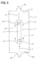
- the heat exchanger 1 having the two tanks 12 at both the upper and lower sides of the core portion 11 is disposed in a heating furnace 3, as shown in FIG. 2.
- Injection ports 33 for injecting the high-temperature gas 2 are provided in an upper surface 31 and a lower surface 32 of the heating furnace 3, so that the high-temperature gas 2 is blown toward the tanks 12 of the heat exchanger 1 from the injection ports 31.
- the arrangement positions of the injection ports 31 are not limited to the upper surface 31 and the lower surface 32 of the heating furnace 3. That is, the arrangement position of each injection port 33 may be suitably set so that the high-temperature gas 2 is preferably blown to the tank portion 12.
- the high-temperature gas 2 is obtained by burning a combustion gas in the atmosphere (air).
- nitrogen gas can be used as the high-temperature gas 2.
- the oxidation of the heat exchanger 1 can effectively prevented.
- the temperature of the high-temperature gas 2 is equal to or higher than 450°C, and a flow speed of the high-temperature gas 2 is equal to or larger than 5 m/s (m/second). Therefore, the time for increasing the temperature of the tanks 12 can be shortened.
- a plate thickness of a metal plate for forming the tanks 12 is about in a range of 0.6-1.0 mm. Therefore, the heat capacity of the tanks 12 is large, and it is difficult to increase the temperature of the tanks 12.
- a plate thickness of a metal plate for forming the core portion 11 is in a range of 0.05-0.15 mm, for example. Therefore, the heat capacity of the core portion 11 is small, and the temperature of the core portion 11 is readily increased.
- the assembly of the heat exchanger 1 is heated by the high-temperature gas 2 in the preheating step as indicated by A in FIG. 3, to a temperature at which the flux on the metal plate is melted.
- the assembly is further heated in the brazing step as indicated by B in FIG. 3, to a temperature at which the brazing filler-metal material in the metal plate is melted.
- the assembly is further cooled until the brazing filler-metal material solidifies.
- the assembly is cooled to the room temperature, so that the heat exchanger 1 including plural brazed members is formed.
- a brazing filler-metal material having the flux thereon is used at bonding portions between the tanks 12 and the tubes 13, and at bonding portions between the tubes 13 and radiation fins 14, so that the brazing of the heat exchanger 1 is performed. Accordingly, the assembly of the heat exchanger 1 is heated at a temperature equal to or lower than a melting temperature of the flux on the brazing filler-metal material, in the preheating step.
- the temperature of the tanks 12 having the large heat capacity is increased earlier than that of the core portion 11 having the small heat capacity, as shown in FIG. 3. That is, the temperature of the tanks 12 that is difficult to be thermally increased is firstly increased. Accordingly, the temperature of the core portion 11 is obediently increased with the thermal increase of the tanks 12 by a heat radiation, a heat circulation or a heat transmission shown by the reference number 21 of FIG. 2. Thereafter, the whole heat exchanger 1 is uniformly heated. Because the core portion 11 having the small heat capacity is readily thermally increased, the temperature of the core portion 11 is readily changed to have an early servility relative to the temperature of the tanks 12.
- the time for increasing the whole heat exchanger 1 can be shortened, and the product efficiency of the heat exchanger 1 can be improved. Because the time for heating the heat exchanger 1 can be shortened, it can restrict diffusion of the brazing filler-metal material to the core portion 11, and erosion in the heat exchanger. Thus, the heat exchanger 1 can be formed to have a sufficient durability, and the thickness of the metal plate for forming the heat exchanger 1 can be made thinner.
- the high-temperature gas 2 is blown to the tanks 12, the temperature of the tanks 12 can be readily accurately increased rapidly. Because the temperature of the high-temperature gas 2 is equal to or higher than 450°C and the flow speed thereof is equal to or larger than 5 m/s, the time for increasing the temperature of the tanks 12 can be sufficiently shortened. Accordingly, the heat exchanger 1 can be accurately brazed without reducing the durability. Thus, according to the method for manufacturing the heat exchanger 1 of the first embodiment, the heat exchanger 1 has an improved durability and an improved product efficiency.
- the temperature of the high-temperature gas 2 is equal to or higher than 450°C and the flow speed thereof is equal to or larger than 5 m/s.
- the temperature of the high-temperature gas 2 can be set in a range of 450-600°C, and the flow speed thereof can be set in a range of 5-15 m/s.
- the temperature of the assembly of the heat exchanger 1 can be readily suitably controlled, and the durability of the heat exchanger 1 can be further improved.
- FIG. 6 The second embodiment of the present invention will be described with reference to FIG. 6.
- a heat exchanger 1 having tanks 12 at right and left two sides of the core portion 11 is manufactured.
- the injection ports 33 of the high-temperature gas 2 are provided at both the right and left sides, so that the high-temperature gas 2 is directly blown to the tanks 12 of the heat exchanger 1.
- the manufacturing method of the heat exchanger 1 of the present invention is compared with that of a comparison example.
- the heat exchanger 1 of the above-described first embodiment is used as a heat exchanger.
- the core portion and the tanks are formed by a metal plate made of a material of A3003, and the brazing filler-metal material is made of a material of A4045.
- the solid line E shows the temperature change of the tanks
- the chain line F shows the temperature change of the core portion.
- the temperature change of the tanks and the temperature change of the core portion of the heat exchanger are measured from the preheating step to the cooling step in the manufacturing method of the present invention.
- the flow speed of the high-temperature gas is set at 12 m/s
- the temperature of the high-temperature gas is set at 600°C.
- the Zn-diffusion depth is measured at a portion around a center of the core portion in the tubes made of a metal plate having a total thickness of 0.2 mm.
- the metal plate at this portion is a clad material constructed by a core material made of A3003 having a thickness of 0.15mm, a sacrificial material made of AI-10Si-2.7Zn having a thickness of 0.03mm, and a brazing filler-metal material made of A4045 having a thickness of 0.02mm.
- the sacrificial material is made of a metal having an electrical potential lower than that of the core material, to be preferentially corroded as compared with the core material.
- the layer of the sacrificial material restricts corrosion in a direction penetrating through the metal plate.
- the corrosion depth of the metal plate is measured when the heat exchanger is placed in a salt-water combined cycle adding a sulphate ion for 500 hours. Further, it is determined whether or the erosion is generated in the brazing, and whether or not a melt of the radiation fin is generated.
- the holding time T for which the temperature of the heat exchanger is maintained to be equal to or higher than 450°C, is set at 8 minutes.
- the holding time T for which the temperature of the heat exchanger is maintained to be equal to or higher than 450°C, is set at 12 minutes.
- the temperature of the tanks is early increased, and the temperature of the core portion is increased obediently in accordance with the temperature increase of the tanks. Thereafter, the temperature of the core portion becomes approximately equal to that of the tanks in the brazing step.
- the time period from the start of the preheating step to the finish of the brazing step is about 7 minutes.
- the heat exchanger is manufactured by a method where an assembly of a heat exchanger is heated without preferentially increasing the temperature of the tanks in the preheating step, and the holding time T is set at 19 minutes. Therefore, in the comparison example, the temperature of the core portion is early increased, and the temperature of the tanks is increased in accordance with the increase of the temperature of the core portion. In the comparison example, the time period from the start of the preheating step to the finish of the brazing step is about 20 minutes.
- the holding time T for which the temperature of the heat exchanger (assembly) is equal to or higher than 450°C, can be made approximately 8 minutes, as shown in FIG. 7. Therefore, the Zn diffusion relative to the metal plate for forming the core portion and the tanks can be restricted. As shown by G in FIG. 8, when the holding time T is about 8 minutes, the depth of the Zn diffusion is smaller than the thickness of the core material. Even when the holding time T is about 12 minutes, the depth of the Zn diffusion is smaller than the thickness of the core material, as shown by H in FIG. 8. Accordingly, as indicated in Table 1, the penetration due to the corrosion, the erosion or the melt of the radiation fin in the obtained heat exchanger is not caused in the present examples I and II of the present invention.
- the depth of the Zn diffusion reaches the thickness of the core material, as shown by I in FIG. 8. Accordingly, as indicated in Table 1, the penetration due to the corrosion, the erosion or the melt of the radiation fin in the obtained heat exchanger is caused in the comparison example.
- the tanks are disposed at both sides of the core portion in the heat exchanger.
- the present invention may be applied to a heat exchanger having a tank only at one side of the core portion.
- the heat exchanger manufactured by the method of the present invention can be used for various heaters, a vehicle radiator, a vehicle condenser, an evaporator, a condenser or the like.
Landscapes
- Engineering & Computer Science (AREA)
- Mechanical Engineering (AREA)
- Heat-Exchange Devices With Radiators And Conduit Assemblies (AREA)
- Pressure Welding/Diffusion-Bonding (AREA)
Abstract
Description
| BRAZING METHOD | HOLDING TIME T (MINUTE) | CORROSION | EROSION | FIN MELTING | |
| DEPTH | RESULT | ||||
| PRESENT EXAMPLE I | ABOUT 8 | 130µm | USABLE | NON | NON |
| PRESENT EXAMPLE II | ABOUT 12 | 150µm | USABLE | NON | NON |
| COMPARISON EXAMPLE | ABOUT 19 | PENETRATE THROUGH | UNUSABLE | GENERATION | GENERATION |
Claims (13)
- A manufacturing method for manufacturing a heat exchanger including a core portion (11) having a plurality of tubes (13) and a plurality of radiation fins (14) connected to surfaces of the tubes (13), and a tank portion (12) communicating with the tubes, the manufacturing method comprising:preheating the heat exchanger until a temperature where a flux in the heat exchanger is melted;heating the heat exchanger after the preheating until a temperature where a brazing material in the heat exchanger is melted; andcooling the heat exchanger after the heating, wherein:in the preheating, a temperature of a first part of the heat exchanger, having a heat capacity larger than a predetermined capacity is increased earlier than a temperature of a second part of the heat exchanger, having a heat capacity smaller than the predetermined capacity.
- The manufacturing method according to claim 1, wherein:the first part is the tank portion, and the second part is the core portion.
- The manufacturing method according to any one of claims 1 and 2, wherein:in the preheating, a high-temperature gas is blown toward the first part to increase the temperature of the first part earlier than that of the second part.
- The manufacturing method according to claim 3, wherein:in the preheating, the high-temperature gas is obtained by burning a combustion gas in air.
- The manufacturing method according to claim 3, wherein:in the preheating, the high-temperature gas is a nitrogen gas.
- The manufacturing method according to any one of claims 3-5, wherein:in the preheating, the high-temperature gas has a temperature equal to higher than 450°C.
- The manufacturing method according to any one of claims 3-6, wherein:in the preheating, the high-temperature gas is blown toward the first part by a flow speed equal to or larger than 5 m/second.
- The manufacturing method according to claim 6, wherein:in the preheating, the high-temperature gas has a temperature in a range of 450-600°C.
- The manufacturing method according to claim 8, wherein:in the preheating, the flow speed of the high-temperature gas blown toward the first part is in a range of 5-15 m/second.
- The manufacturing method according to any one of claims 1-9, wherein:in the preheating, the temperature of the second part increases obediently in accordance with an increase of the temperature of the first part.
- The manufacturing method according to any one of claims 1-9, wherein:the tank portion has two tanks at opposite sides of the core portion; andin the preheating, the temperature of the tanks is increased earlier than that of the core portion.
- The manufacturing method according to claim 11, wherein:in the preheating, high-temperature gas is blown to the tanks.
- The manufacturing method according to any one of claims 1-12, wherein:the cooling includes a first cooling step for gradually cooling the heat exchanger after the heating to a temperature where the brazing material is solidified, and a second cooling step for further cooling the heat exchanger to a room temperature after the first cooling step.
Applications Claiming Priority (2)
| Application Number | Priority Date | Filing Date | Title |
|---|---|---|---|
| JP2001205261 | 2001-07-05 | ||
| JP2001205261 | 2001-07-05 |
Publications (3)
| Publication Number | Publication Date |
|---|---|
| EP1273377A2 true EP1273377A2 (en) | 2003-01-08 |
| EP1273377A3 EP1273377A3 (en) | 2004-09-15 |
| EP1273377B1 EP1273377B1 (en) | 2007-11-28 |
Family
ID=19041603
Family Applications (1)
| Application Number | Title | Priority Date | Filing Date |
|---|---|---|---|
| EP02014871A Expired - Lifetime EP1273377B1 (en) | 2001-07-05 | 2002-07-04 | Manufacturing method of heat exchanger |
Country Status (5)
| Country | Link |
|---|---|
| US (1) | US6625886B2 (en) |
| EP (1) | EP1273377B1 (en) |
| CN (1) | CN1199753C (en) |
| CZ (1) | CZ302437B6 (en) |
| DE (1) | DE60223755T2 (en) |
Cited By (1)
| Publication number | Priority date | Publication date | Assignee | Title |
|---|---|---|---|---|
| WO2013073947A1 (en) * | 2011-11-14 | 2013-05-23 | Norsk Hydro Asa | Method for manufacturing tube plate fin heat exchangers |
Families Citing this family (7)
| Publication number | Priority date | Publication date | Assignee | Title |
|---|---|---|---|---|
| JP4248433B2 (en) * | 2003-04-08 | 2009-04-02 | 株式会社デンソー | Method for brazing Mg-containing aluminum alloy material |
| US7107680B2 (en) * | 2003-06-20 | 2006-09-19 | Denso Corporation | Manufacturing method of heat exchanger and structure thereof |
| DE102008047498A1 (en) * | 2008-09-17 | 2010-04-15 | Emitec Gesellschaft Für Emissionstechnologie Mbh | Method for soldering a metallic honeycomb body and for exhaust gas treatment |
| JP5577616B2 (en) * | 2009-04-06 | 2014-08-27 | 株式会社デンソー | Heat exchanger tubes and heat exchangers |
| CN101898267B (en) * | 2009-10-19 | 2011-12-07 | 无锡佳龙换热器制造有限公司 | Method for manufacturing aluminum plate-fin heat exchanger |
| CN102259227B (en) * | 2010-05-25 | 2013-06-19 | 广东万和新电气股份有限公司 | Method for welding heat exchanger in gas water heater |
| CN117086562B (en) * | 2023-01-17 | 2026-02-06 | 株洲时代金属制造有限公司 | Brazing device for aluminum alloy sheet type radiator |
Family Cites Families (21)
| Publication number | Priority date | Publication date | Assignee | Title |
|---|---|---|---|---|
| GB1245274A (en) * | 1968-10-22 | 1971-09-08 | Pyronics Inc | Method and apparatus for brazing |
| US3833986A (en) * | 1973-06-04 | 1974-09-10 | Sundstrand Heat Transfer Inc | Method of making heat exchanger |
| US4054239A (en) * | 1976-03-31 | 1977-10-18 | Carrier Corporation | Process for fabricating a heat exchanger |
| US4291450A (en) * | 1979-10-05 | 1981-09-29 | Ford Motor Company | Method and apparatus for manufacturing finned heat exchangers |
| JPS5832572A (en) * | 1981-08-19 | 1983-02-25 | Matsushita Electric Ind Co Ltd | Joining method for pipe materials |
| JPS6363567A (en) * | 1986-09-04 | 1988-03-19 | Showa Alum Corp | Production of heat exchanger having excellent corrosion resistance |
| AU8274587A (en) * | 1986-11-17 | 1988-06-16 | Furukawa Aluminum Co., Ltd. | Process for manufacturing heat exchanger |
| US4989775A (en) * | 1987-12-15 | 1991-02-05 | Showa Aluminum Kabushiki Kaisha | Method for brazing aluminum components |
| JPH0240489A (en) * | 1988-07-29 | 1990-02-09 | Furukawa Electric Co Ltd:The | Re-flow furnace |
| JPH03118962A (en) * | 1989-10-03 | 1991-05-21 | Hitachi Techno Eng Co Ltd | Vapor reflow soldering equipment |
| JP2825949B2 (en) * | 1990-07-26 | 1998-11-18 | サンデン株式会社 | Brazing method |
| JPH07115163B2 (en) * | 1991-09-30 | 1995-12-13 | 昭和アルミニウム株式会社 | Heat exchanger manufacturing method |
| JP3330987B2 (en) * | 1992-11-10 | 2002-10-07 | 誠 西村 | Metal brazing method and apparatus |
| GB9312328D0 (en) * | 1993-06-15 | 1993-07-28 | Lexor Technology Limited | A method of brazing |
| US5322209A (en) * | 1993-07-19 | 1994-06-21 | General Motors Corporation | Aluminum heat exchanger brazing method and apparatus |
| JP3663688B2 (en) * | 1994-09-30 | 2005-06-22 | 株式会社デンソー | Heat exchanger |
| JP3674058B2 (en) * | 1994-10-11 | 2005-07-20 | 株式会社デンソー | Manufacturing method of stacked heat exchanger |
| JPH09234559A (en) * | 1996-02-29 | 1997-09-09 | Ezaki Kogyo Kk | Brazing method and brazing device |
| ATE221814T1 (en) * | 1997-05-06 | 2002-08-15 | Showa Denko Kk | FLUX COMPOSITION FOR SOLDERING ALUMINUM MATERIAL AND METHOD FOR SOLDERING |
| DE69808565T2 (en) * | 1997-07-16 | 2003-02-13 | Denso Corp., Kariya | Aluminum alloy tube and heat exchanger, and method for metal spraying a filler metal |
| CZ287095B6 (en) * | 1998-11-03 | 2000-09-13 | Themis A. S. | Temperature control method of part heating during automatic soldering and apparatus for making the same |
-
2002
- 2002-06-17 US US10/173,301 patent/US6625886B2/en not_active Expired - Fee Related
- 2002-07-04 EP EP02014871A patent/EP1273377B1/en not_active Expired - Lifetime
- 2002-07-04 CZ CZ20022350A patent/CZ302437B6/en not_active IP Right Cessation
- 2002-07-04 DE DE60223755T patent/DE60223755T2/en not_active Expired - Lifetime
- 2002-07-04 CN CNB02141114XA patent/CN1199753C/en not_active Expired - Fee Related
Cited By (1)
| Publication number | Priority date | Publication date | Assignee | Title |
|---|---|---|---|---|
| WO2013073947A1 (en) * | 2011-11-14 | 2013-05-23 | Norsk Hydro Asa | Method for manufacturing tube plate fin heat exchangers |
Also Published As
| Publication number | Publication date |
|---|---|
| US6625886B2 (en) | 2003-09-30 |
| DE60223755T2 (en) | 2008-11-20 |
| EP1273377B1 (en) | 2007-11-28 |
| CZ20022350A3 (en) | 2003-02-12 |
| DE60223755D1 (en) | 2008-01-10 |
| CN1396033A (en) | 2003-02-12 |
| CN1199753C (en) | 2005-05-04 |
| US20030033715A1 (en) | 2003-02-20 |
| CZ302437B6 (en) | 2011-05-18 |
| EP1273377A3 (en) | 2004-09-15 |
Similar Documents
| Publication | Publication Date | Title |
|---|---|---|
| JP5279514B2 (en) | HEAT EXCHANGER, ITS MANUFACTURING METHOD, AND AIR CONDITIONER HAVING THE HEAT EXCHANGER | |
| JP6046704B2 (en) | Alloy for heat exchange tube with internal protective cladding and brazed turbulator | |
| US5806752A (en) | Manufacture of aluminum assemblies by open-air flame brazing | |
| US20010030039A1 (en) | Aluminum-copper clad member, method of manufacturing the same, and heat sink | |
| US6234243B1 (en) | Heat exchanger assembly with magnesium barrier | |
| US5771962A (en) | Manufacture of heat exchanger assembly by cab brazing | |
| US11007592B2 (en) | Heat exchanger and method for producing same | |
| US6371201B1 (en) | Heat exchanger and method of assembly for automotive vehicles | |
| EP1089369A3 (en) | Heat exchanger for cooling circulating water of fuel cells & process for producing same | |
| EP1273377A2 (en) | Manufacturing method of heat exchanger | |
| JP2002137054A (en) | Heat exchanger manufacturing method and heat exchanger | |
| EP1400300A1 (en) | Layered heat-resistant alloy plate and method of producing the same | |
| KR20050084231A (en) | Aluminum alloy brazing material, brazing member, brazed article and brazing method therefor using said material, brazing heat exchanging tube, heat exchanger and manufacturing method thereof using said brazing heat exchanging tube | |
| JP6743846B2 (en) | Laminated heat exchanger and method for manufacturing the laminated heat exchanger | |
| JP2003080366A (en) | Heat exchanger manufacturing method | |
| GB2357300A (en) | Flux for brazing an aluminium heat exchanger based on fluorides | |
| JP2002286394A (en) | Heat exchanger | |
| JPH1089881A (en) | Laminated type heat exchanger | |
| CN119525943B (en) | A method for processing a thin stainless steel plate-fin type heat dissipation core | |
| JP2005254320A (en) | Manufacturing method of heat exchanger | |
| JP2005083673A (en) | Laminate heat exchanger | |
| TWI919679B (en) | Joint and its manufacturing method | |
| JP2003294389A (en) | Heat exchanger and method of manufacturing heat exchanger | |
| JP2005193264A (en) | Manufacturing method of heat exchanger | |
| US20090107658A1 (en) | Metallic material for brazing, brazing method, and heat exchanger |
Legal Events
| Date | Code | Title | Description |
|---|---|---|---|
| PUAI | Public reference made under article 153(3) epc to a published international application that has entered the european phase |
Free format text: ORIGINAL CODE: 0009012 |
|
| AK | Designated contracting states |
Kind code of ref document: A2 Designated state(s): AT BE BG CH CY CZ DE DK EE ES FI FR GB GR IE IT LI LU MC NL PT SE SK TR |
|
| AX | Request for extension of the european patent |
Free format text: AL;LT;LV;MK;RO;SI |
|
| PUAL | Search report despatched |
Free format text: ORIGINAL CODE: 0009013 |
|
| AK | Designated contracting states |
Kind code of ref document: A3 Designated state(s): AT BE BG CH CY CZ DE DK EE ES FI FR GB GR IE IT LI LU MC NL PT SE SK TR |
|
| AX | Request for extension of the european patent |
Extension state: AL LT LV MK RO SI |
|
| 17P | Request for examination filed |
Effective date: 20041015 |
|
| AKX | Designation fees paid |
Designated state(s): DE FR GB IT |
|
| 17Q | First examination report despatched |
Effective date: 20050427 |
|
| GRAP | Despatch of communication of intention to grant a patent |
Free format text: ORIGINAL CODE: EPIDOSNIGR1 |
|
| GRAS | Grant fee paid |
Free format text: ORIGINAL CODE: EPIDOSNIGR3 |
|
| GRAA | (expected) grant |
Free format text: ORIGINAL CODE: 0009210 |
|
| AK | Designated contracting states |
Kind code of ref document: B1 Designated state(s): DE FR GB IT |
|
| REF | Corresponds to: |
Ref document number: 60223755 Country of ref document: DE Date of ref document: 20080110 Kind code of ref document: P |
|
| ET | Fr: translation filed | ||
| PLBE | No opposition filed within time limit |
Free format text: ORIGINAL CODE: 0009261 |
|
| STAA | Information on the status of an ep patent application or granted ep patent |
Free format text: STATUS: NO OPPOSITION FILED WITHIN TIME LIMIT |
|
| 26N | No opposition filed |
Effective date: 20080829 |
|
| PGFP | Annual fee paid to national office [announced via postgrant information from national office to epo] |
Ref country code: GB Payment date: 20120704 Year of fee payment: 11 |
|
| PGFP | Annual fee paid to national office [announced via postgrant information from national office to epo] |
Ref country code: DE Payment date: 20120627 Year of fee payment: 11 Ref country code: FR Payment date: 20120719 Year of fee payment: 11 Ref country code: IT Payment date: 20120714 Year of fee payment: 11 |
|
| GBPC | Gb: european patent ceased through non-payment of renewal fee |
Effective date: 20130704 |
|
| REG | Reference to a national code |
Ref country code: FR Ref legal event code: ST Effective date: 20140331 |
|
| PG25 | Lapsed in a contracting state [announced via postgrant information from national office to epo] |
Ref country code: DE Free format text: LAPSE BECAUSE OF NON-PAYMENT OF DUE FEES Effective date: 20140201 Ref country code: GB Free format text: LAPSE BECAUSE OF NON-PAYMENT OF DUE FEES Effective date: 20130704 |
|
| REG | Reference to a national code |
Ref country code: DE Ref legal event code: R119 Ref document number: 60223755 Country of ref document: DE Effective date: 20140201 |
|
| PG25 | Lapsed in a contracting state [announced via postgrant information from national office to epo] |
Ref country code: FR Free format text: LAPSE BECAUSE OF NON-PAYMENT OF DUE FEES Effective date: 20130731 Ref country code: IT Free format text: LAPSE BECAUSE OF NON-PAYMENT OF DUE FEES Effective date: 20130704 |