EP1272366B1 - Draw beam - Google Patents
Draw beam Download PDFInfo
- Publication number
- EP1272366B1 EP1272366B1 EP01920041A EP01920041A EP1272366B1 EP 1272366 B1 EP1272366 B1 EP 1272366B1 EP 01920041 A EP01920041 A EP 01920041A EP 01920041 A EP01920041 A EP 01920041A EP 1272366 B1 EP1272366 B1 EP 1272366B1
- Authority
- EP
- European Patent Office
- Prior art keywords
- holes
- draw beam
- vehicle
- connecting elements
- draw
- Prior art date
- Legal status (The legal status is an assumption and is not a legal conclusion. Google has not performed a legal analysis and makes no representation as to the accuracy of the status listed.)
- Expired - Lifetime
Links
Images

Classifications
-
- B—PERFORMING OPERATIONS; TRANSPORTING
- B60—VEHICLES IN GENERAL
- B60D—VEHICLE CONNECTIONS
- B60D1/00—Traction couplings; Hitches; Draw-gear; Towing devices
- B60D1/48—Traction couplings; Hitches; Draw-gear; Towing devices characterised by the mounting
- B60D1/485—Traction couplings; Hitches; Draw-gear; Towing devices characterised by the mounting mounted by means of transversal members attached to the frame of a vehicle
-
- B—PERFORMING OPERATIONS; TRANSPORTING
- B62—LAND VEHICLES FOR TRAVELLING OTHERWISE THAN ON RAILS
- B62D—MOTOR VEHICLES; TRAILERS
- B62D21/00—Understructures, i.e. chassis frame on which a vehicle body may be mounted
- B62D21/02—Understructures, i.e. chassis frame on which a vehicle body may be mounted comprising longitudinally or transversely arranged frame members
-
- B—PERFORMING OPERATIONS; TRANSPORTING
- B62—LAND VEHICLES FOR TRAVELLING OTHERWISE THAN ON RAILS
- B62D—MOTOR VEHICLES; TRAILERS
- B62D25/00—Superstructure or monocoque structure sub-units; Parts or details thereof not otherwise provided for
- B62D25/20—Floors or bottom sub-units
- B62D25/209—Arrangements for the mounting of vehicle hitches
Definitions
- the present invention relates to a draw beam arrangement for a vehicle having at least two longitudinally arranged frame beams and, at the rear end section of said frame beams, a connecting portion extending therebetween, comprising two connecting elements and a draw beam arranged between them, said connecting elements exhibiting a first set of through holes and a second set of through holes according to the preamble of the appended claim 1.
- a draw beam arrangement is previously known from the US Patent No 5,511,813 .
- Draw arrangements of the kind stated above generally comprises a draw beam fixedly attached to the vehicle and a draw arrangement supported by said draw beam, for example in the form of a ball type tow hook, or a towing pin arranged between two horizontal plates.
- Another known solution for enabling adaptation of the location of the draw arrangement is to provide the frame beams of the vehicle with a large number of closely located through holes, whereby the end sections of the draw beam are connected to those holes corresponding most closely with the required location of the draw arrangement.
- the arrangement comprises two connecting elements functioning to connect, by means of screw connections, the longitudinal frame beams of a vehicle with a transversal draw beam.
- the connecting elements are provided with several through holes having elongated cross sections.
- the draw beam is further provided with a draw arrangement comprising a beam element formed with a horizontal beam portion welded to a vertical beam portion, onto which a ball type tow hook is affixed.
- the tow hook is adjustably arranged in the vertical direction on the vertical beam portion.
- Said horizontal beam portion is displaceably arranged, in the vehicle longitudinal direction, in a support fixedly attached to the draw beam. This arrangement enables adjustment of the location of the tow hook in the longitudinal direction of the vehicle.
- the patent document DE 29606636 U1 discloses a device for coupling a trailer to a towing vehicle.
- the coupling device comprises a component which is arranged transversely to the longitudinal direction of the vehicle, between two side parts.
- the side parts are connected to frame elements of the vehicle.
- the document EP 0950551 teaches an arrangement comprising a cross-member device for connecting a trailer to a towing vehicle.
- the cross-member device comprises a cross-bar which is arranged between two connecting elements which are fixed to a frame of the vehicle in question.
- the object of the present invention is to provide a draw beam arrangement for vehicles, such as lorries, allowing good adaptability of the location of the draw arrangement, especially in the longitudinal direction of the vehicle, to the type of trailer that is to be connected to the vehicle, thereby enabling an optimum distance between the tractor vehicle and the trailer to be obtained.
- the draw beam arrangement according to the invention comprises two connecting elements and a draw beam arranged between them.
- Said connecting elements exhibit a first set of through holes intended- for connection with the longitudinal frame beams of the vehicle, and a second set of through holes intended for connection with said draw beam.
- first set of through holes being offset in relation to said second set of through holes the effect will be obtained, if the connecting elements are rotated half a turn about an imaginary axis transversal to the vehicle lon-gitudinal direction, in connection with assembly, that the draw beam is displaced in the longitudinal direction of the vehicle whilst using the same holes in the frame beam. This allows an optimum distance between the tractor vehicle and the trailer to be achieved.
- a further advantage of the draw beam arrangement according to the invention is that it has a relatively simple structure and therefore will be simpler and less costly to manufacture.
- the first and second sets of through holes in the connecting elements are offset, in relation to each other, a distance corresponding to one fourth of the distance between two adjacent through holes provided in the frame beam. This entails that if the connecting elements are rotated half a turn, the draw beam will be displaced by a distance corresponding to half the distance between two adjacent through holes provided in the frame beam, thus obtaining twice the number of possible equivalent draw beam positions without the number of through holes in the frame beams having to be increased and/or located closer to each other.
- vertical beams are also provided between the vehicle frame beams and said draw beam, preferably between said connecting elements and the draw beam. In this manner vertical adjustment of the draw beam location is also enabled.
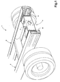
- Fig. 1 illustrates a perspective view of a draw beam arrangement 1 according to the present invention, arranged on a vehicle having two frame beams 2, 3 provided in the longitudinal direction of the vehicle. At the rear end section of the frame beams 2, 3, and between them, extends a connecting portion 4, including two connecting elements 5, 6 and a draw beam 7 arranged therebetween.
- the connecting elements 5, 6 are connected on the one hand with the frame beams 2, 3, and on the other with the draw beam 7, by means of screw or rivet connections.
- screw connections One advantage of using screw connections is that they are relatively simple to disassemble.
- the frame beams 2, 3 are shaped like U-beams with a vertical middle section 8, 9 and upper 10, 11 and lower 12, 13 flanges, together providing the rigidity of the frame beams 2, 3.
- the frame beams 2, 3 are shaped like U-beams with a vertical middle section 8, 9 and upper 10, 11 and lower 12, 13 flanges, together providing the rigidity of the frame beams 2, 3.
- the connecting elements 5, 6 are formed with an upper 16, 17 and a lower 18, 19 angled plate that are joined, preferably riveted, with an intermediate U-beam 20, 21.
- the angled plates 16, 17, 18, 19 of the connecting elements 5,6 are provided, on the side facing the frame beams 2, 3, with a first set of through holes 22, 23, and the U-beams thereof are provided, on the side facing the draw beam 7, with a second set of through holes 24, 25.
- Said first set of through holes 22, 23 is hereby offset, in relation to said second set of through holes 24, 25, by a distance corresponding to one fourth of the distance between two adjacent holes in the respective frame beam 2, 3.
- the draw beam 7 is formed with lateral elements 26, 27 and with a U-beam 28 arranged therebetween, the latter being welded to said lateral elements 26, 27.
- the lateral elements 26, 27 are provided with a set of through holes 29, the number and configuration of which coincide with the second set of through holes 24, 25 of the connecting elements 5, 6.
- the draw beam 7 also exhibits further through holes 30 and an aperture 31, serving as the attachment point for a draw arrangement, for example a ball type tow hook. Thanks to the relatively simple form of the draw beam, using plates bent in one plane only, like those of the connecting elements 5, 6, the use of relatively strong/thick plates is facilitated, which contributes to giving the design its rigidity.
- Fig. 3 shows a perspective view of an alternative preferred embodiment of the draw beam arrangement 1 according to the present invention.
- two vertical U-beams 32, 33 are provided, which displace the vertical location of the draw beam 7.
- Said vertical U-beams are each provided with two sets of through holes, an upper set 34, 35 and a lower set 36, 37, the numbers and configurations of which coincide with the second set of through holes 24, 25 in the connecting elements 5, 6 and the through holes 29 provided in the lateral elements 26, 27 of the draw beam 7, respectively.
- the distance by which said first set of through holes is offset in relation to said second set of through holes could be greater or smaller than one fourth of the distance between two adjacent holes in the respective frame beam.
- the connecting elements may be shaped so as to allow rotation only a quarter turn, whereby the draw beam will be displaced also in the vertical direction, together with a shorter distance in the longitudinal direction of the vehicle, compared to the corresponding rotation with half a turn.
Landscapes
- Engineering & Computer Science (AREA)
- Transportation (AREA)
- Mechanical Engineering (AREA)
- Chemical & Material Sciences (AREA)
- Combustion & Propulsion (AREA)
- Body Structure For Vehicles (AREA)
- Yarns And Mechanical Finishing Of Yarns Or Ropes (AREA)
- Surgical Instruments (AREA)
- Telephone Function (AREA)
- Cookers (AREA)
Abstract
Description
- The present invention relates to a draw beam arrangement for a vehicle having at least two longitudinally arranged frame beams and, at the rear end section of said frame beams, a connecting portion extending therebetween, comprising two connecting elements and a draw beam arranged between them, said connecting elements exhibiting a first set of through holes and a second set of through holes according to the preamble of the appended claim 1. Such a draw beam arrangement is previously known from the
US Patent No 5,511,813 . - When manufacturing commercial vehicles, such as lorries, it is today common to offer various kinds of towing or draw arrangements, allowing a trailer to be connected to the vehicle.
- Draw arrangements of the kind stated above generally comprises a draw beam fixedly attached to the vehicle and a draw arrangement supported by said draw beam, for example in the form of a ball type tow hook, or a towing pin arranged between two horizontal plates.
- When hooking a trailer onto a tractor vehicle, it is advantageous from an aerodynamic aspect to minimise the distance between the tractor and the trailer. However, a certain minimum distance has to be maintained in order to avoid the trailer bumping into the tractor, e.g. when negotiating sharp corners.
- Consequently, there is a requirement for enabling adaptation of the draw arrangement location, especially in the vehicle longitudinal direction, to the type of trailer that is to be connected to the vehicle. This is resolved by the above draw beam being manufactured in a multitude of different embodiments in order to enable the required adaptation.
- However, the procedure discussed above is not cost-effective, as both manufacture and storage will be expensive due to the relatively small production series. Furthermore, changes of location are not allowed after delivery.
- Another known solution for enabling adaptation of the location of the draw arrangement is to provide the frame beams of the vehicle with a large number of closely located through holes, whereby the end sections of the draw beam are connected to those holes corresponding most closely with the required location of the draw arrangement.
- This is however rather costly, as more time is required at the production stage. Further, such a solution with closely located through holes could lead to lower strength of the frame beams, entailing the necessity of providing reinforcements.
- From
US Patent No 5,511,813 a draw beam arrangement is previously known, which is intended for use with a multitude of different vehicle models, and therefore exhibits a number of adjustment possibilities. The arrangement comprises two connecting elements functioning to connect, by means of screw connections, the longitudinal frame beams of a vehicle with a transversal draw beam. To allow adjustment of the width of the arrangement in dependence of the spacing of the frame beams, the connecting elements are provided with several through holes having elongated cross sections. The draw beam is further provided with a draw arrangement comprising a beam element formed with a horizontal beam portion welded to a vertical beam portion, onto which a ball type tow hook is affixed. The tow hook is adjustably arranged in the vertical direction on the vertical beam portion. Said horizontal beam portion is displaceably arranged, in the vehicle longitudinal direction, in a support fixedly attached to the draw beam. This arrangement enables adjustment of the location of the tow hook in the longitudinal direction of the vehicle. - Although the known arrangement allows satisfactory adaptation of the location of the draw arrangement, it has certain disadvantages. One disadvantage, caused by the draw beam arrangement being intended for use with a number of different vehicle models and thus exhibiting numerous adjustment possibilities, is that this entails that the known arrangement will have a relatively complex structure and thus will be relatively costly to manufacture. Another drawback is that the design tends to be relatively weak and thus not to be suitable for use with heavy-duty vehicles, such as lorries, where the load stress will be very high.
- The patent document
DE 29606636 U1 discloses a device for coupling a trailer to a towing vehicle. The coupling device comprises a component which is arranged transversely to the longitudinal direction of the vehicle, between two side parts. The side parts are connected to frame elements of the vehicle. - Furthermore, the document
EP 0950551 teaches an arrangement comprising a cross-member device for connecting a trailer to a towing vehicle. In particular, the cross-member device comprises a cross-bar which is arranged between two connecting elements which are fixed to a frame of the vehicle in question. - The object of the present invention is to provide a draw beam arrangement for vehicles, such as lorries, allowing good adaptability of the location of the draw arrangement, especially in the longitudinal direction of the vehicle, to the type of trailer that is to be connected to the vehicle, thereby enabling an optimum distance between the tractor vehicle and the trailer to be obtained.
- This object is achieved by the invention described in claim 1. Preferred embodiments of the invention are described in the subsequent claims.
- The draw beam arrangement according to the invention comprises two connecting elements and a draw beam arranged between them. Said connecting elements exhibit a first set of through holes intended- for connection with the longitudinal frame beams of the vehicle, and a second set of through holes intended for connection with said draw beam. Through said first set of through holes being offset in relation to said second set of through holes the effect will be obtained, if the connecting elements are rotated half a turn about an imaginary axis transversal to the vehicle lon-gitudinal direction, in connection with assembly, that the draw beam is displaced in the longitudinal direction of the vehicle whilst using the same holes in the frame beam. This allows an optimum distance between the tractor vehicle and the trailer to be achieved. A further advantage of the draw beam arrangement according to the invention is that it has a relatively simple structure and therefore will be simpler and less costly to manufacture.
- According to a preferred embodiment, the first and second sets of through holes in the connecting elements are offset, in relation to each other, a distance corresponding to one fourth of the distance between two adjacent through holes provided in the frame beam. This entails that if the connecting elements are rotated half a turn, the draw beam will be displaced by a distance corresponding to half the distance between two adjacent through holes provided in the frame beam, thus obtaining twice the number of possible equivalent draw beam positions without the number of through holes in the frame beams having to be increased and/or located closer to each other.
- According to a further preferred embodiment of the present invention, vertical beams are also provided between the vehicle frame beams and said draw beam, preferably between said connecting elements and the draw beam. In this manner vertical adjustment of the draw beam location is also enabled.
- Further advantages and objects of the invention may be gathered from the appended claims and the accompanying description.
- The invention will be described below, in connection with preferred embodiment examples and the accompanying drawings, of which:
- Fig. 1
- is a perspective view of a preferred embodiment of a draw beam arrangement according to the present invention;
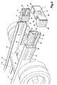
- Fig. 2
- is a perspective view of the draw beam arrangement of Fig. 1 in a disassembled state; and
- Fig. 3
- is a perspective view of a further preferred embodiment of the draw beam arrangement according to the present invention.
- Fig. 1 illustrates a perspective view of a draw beam arrangement 1 according to the present invention, arranged on a vehicle having two
frame beams frame beams elements 5, 6 and adraw beam 7 arranged therebetween. The connectingelements 5, 6 are connected on the one hand with theframe beams draw beam 7, by means of screw or rivet connections. One advantage of using screw connections is that they are relatively simple to disassemble. - With reference now to Fig. 2, the components comprised in the draw beam arrangement 1 will be described in further detail. In the illustrated example the
frame beams vertical middle section frame beams frame beams holes draw beam 7, a relatively good adaptation is achieved of the location of thedraw beam 7 in relation to the type of trailer to be connected to the vehicle. Furthermore, a modification of the location of thedraw beam 7 is possible subsequent to vehicle delivery, without having to make further throughholes - The
connecting elements 5, 6 are formed with an upper 16, 17 and a lower 18, 19 angled plate that are joined, preferably riveted, with anintermediate U-beam angled plates elements 5,6 are provided, on the side facing theframe beams holes draw beam 7, with a second set of throughholes holes holes respective frame beam elements 5, 6 are rotated, in connection with assembly, half a turn about an imaginary axis transversal to the vehicle longitudinal direction, thedraw beam 7 will be displaced a distance corresponding to half the distance between two adjacent throughholes frame beam same holes holes elements 5, 6, with plates angled in one plane only, the use of relatively strong/thick plates is facilitated, which contributes to giving the design the required rigidity, especially for heavy duty vehicle applications, such as lorries, where the load stress will be high. - The
draw beam 7 is formed withlateral elements lateral elements lateral elements holes 29, the number and configuration of which coincide with the second set of throughholes elements 5, 6. Thedraw beam 7 also exhibits further throughholes 30 and anaperture 31, serving as the attachment point for a draw arrangement, for example a ball type tow hook. Thanks to the relatively simple form of the draw beam, using plates bent in one plane only, like those of the connectingelements 5, 6, the use of relatively strong/thick plates is facilitated, which contributes to giving the design its rigidity. - Fig. 3 shows a perspective view of an alternative preferred embodiment of the draw beam arrangement 1 according to the present invention. Between the connecting
elements 5, 6 and thedraw beam 7, two vertical U-beams 32, 33 are provided, which displace the vertical location of thedraw beam 7. Said vertical U-beams are each provided with two sets of through holes, anupper set lower set holes elements 5, 6 and the throughholes 29 provided in thelateral elements draw beam 7, respectively. - The invention will not be limited to the embodiment examples described above and illustrated in the drawings, but other embodiments are also conceivable. For example, the distance by which said first set of through holes is offset in relation to said second set of through holes could be greater or smaller than one fourth of the distance between two adjacent holes in the respective frame beam. Finally, the connecting elements may be shaped so as to allow rotation only a quarter turn, whereby the draw beam will be displaced also in the vertical direction, together with a shorter distance in the longitudinal direction of the vehicle, compared to the corresponding rotation with half a turn. Thus, adaptation of the vehicle draw arrangement to the height of the trailer is also allowed.
Claims (6)
- A draw beam arrangement for a vehicle having at least two frame beams (2, 3) arranged in the longitudinal direction of the vehicle and, at the rear end section of said frame beams (2, 3), a connecting portion (4) extending therebetween, comprising two connecting elements (5,6) and a draw beam (7) arranged between them, said connecting elements (5,6) exhibiting a first set of through holes (22,23) for connection with the longitudinal frame beams of the vehicle and a second set of through holes (24,25) for connection with said draw beam, characterised in that said first set of through holes (22,23) is offset in relation to said second set of through holes (24,25), wherein said first set of through holes (22,23) is offset, when the connecting elements (5,6) are arranged at the rear end section of the frame beams (2,3), in the longitudinal direction of the vehicle in relation to said second set of through holes (24,25) so as to obtain a displacement of the draw beam in the longitudinal direction of the vehicle when the connecting elements are rotated half a turn about an imaginary axis transversal to the vehicle longitudinal direction, while using the same holes in the frame beams.
- The draw beam arrangement for a vehicle according to claim 1, characterised in that said first set of through holes (22, 23) is offset, in relation to said second set of through holes (24, 25), by a distance corresponding to one fifth up to one third of the distance between two adjacent through holes (14, 15) provided in the frame beam (2, 3).
- The draw beam arrangement for a vehicle according to claim 2, characterised in that said first set of through holes (22, 23) is offset, in relation to said second set of through holes (24, 25), by a distance corresponding to about one fourth of the distance between two adjacent through holes(14, 15) provided in the frame beam (2, 3).
- A draw beam arrangement for a vehicle according to any one of the preceding claims, characterised in that said first set of through holes (22, 23) is intended to co-operate, when the connecting elements (5, 6) are arranged at the rear end section of the frame beams (2, 3), with the through holes (14, 15) provided in said frame beams (2, 3).
- A draw beam arrangement for a vehicle according to any one of the preceding claims, characterised in that two generally vertical beams (32, 33) are arranged between the frame beams (2, 3) and the draw beam (7).
- The draw beam arrangement for a vehicle according to claim 5, characterised in that said vertical beams (32, 33) are arranged between the connecting elements (5, 6) and the draw beam (7).
Applications Claiming Priority (3)
| Application Number | Priority Date | Filing Date | Title |
|---|---|---|---|
| SE0001319A SE518652C2 (en) | 2000-04-11 | 2000-04-11 | Drawbar arrangement of a vehicle |
| SE0001319 | 2000-04-11 | ||
| PCT/SE2001/000739 WO2001076896A1 (en) | 2000-04-11 | 2001-04-05 | Draw beam |
Publications (2)
| Publication Number | Publication Date |
|---|---|
| EP1272366A1 EP1272366A1 (en) | 2003-01-08 |
| EP1272366B1 true EP1272366B1 (en) | 2007-06-27 |
Family
ID=20279256
Family Applications (1)
| Application Number | Title | Priority Date | Filing Date |
|---|---|---|---|
| EP01920041A Expired - Lifetime EP1272366B1 (en) | 2000-04-11 | 2001-04-05 | Draw beam |
Country Status (6)
| Country | Link |
|---|---|
| EP (1) | EP1272366B1 (en) |
| AT (1) | ATE365648T1 (en) |
| BR (1) | BR0109843B1 (en) |
| DE (1) | DE60129115T2 (en) |
| SE (1) | SE518652C2 (en) |
| WO (1) | WO2001076896A1 (en) |
Cited By (1)
| Publication number | Priority date | Publication date | Assignee | Title |
|---|---|---|---|---|
| EP2404810A1 (en) * | 2010-07-05 | 2012-01-11 | VBG Group AB (Publ) | Reinforcement member for a draw beam, and a draw beam with such a reinforcement member |
Families Citing this family (17)
| Publication number | Priority date | Publication date | Assignee | Title |
|---|---|---|---|---|
| AU763140B2 (en) * | 1999-05-12 | 2003-07-17 | Bartlett Transport Improvements Pty. Ltd. | A towbar assembly |
| EP1375248B1 (en) * | 2002-06-19 | 2005-08-10 | Gerd Bär | Loading tailgate |
| DE10303338A1 (en) * | 2003-01-29 | 2004-08-19 | Schmitz Gotha Fahrzeugwerke Gmbh | Drawbar arrangement for trailers |
| SE522194C2 (en) * | 2003-02-04 | 2004-01-20 | Vbg Ab | Trailer coupling and drawbar |
| FR2853296A1 (en) * | 2003-04-03 | 2004-10-08 | Sarl Loradec | Sub-frame for assembling open carrier on truck, has rear cross-bar equipped with holes and fixed to rails having another set of holes by bolting, and out-trigger beam gliding in hollow shaft |
| DE102004051954B4 (en) | 2004-10-22 | 2008-10-02 | Markus Göppel GmbH & Co. | Trailer coupling device for a self-supporting body skeleton and self-supporting body skeleton |
| DE102005015423A1 (en) * | 2005-04-04 | 2006-10-05 | Man Nutzfahrzeuge Ag | Closure cross bar for use in commercial vehicle, has mounting lug vertically arranged on both sides of middle bar, extending over entire height of bar and including holes that are arranged in mounting planes of other mounting lugs |
| DE102005015389A1 (en) * | 2005-04-04 | 2006-10-05 | Man Nutzfahrzeuge Ag | Height adjustable cross beam for commercial motor vehicle, attaches pair of connection consoles at both ends of central section between two side members as such central section is positioned to any height relative to top of side members |
| ATE450386T1 (en) | 2006-12-13 | 2009-12-15 | Vbg Group Ab Publ | TIE ROD SUSPENSION |
| EP2219934B1 (en) * | 2007-12-06 | 2013-11-06 | Volvo Lastvagnar AB | A beam for a heavy vehicle |
| DE102008012622A1 (en) † | 2008-02-28 | 2009-09-10 | Scambia Industrial Developments Aktiengesellschaft | Towing |
| FR2948065B1 (en) * | 2009-07-17 | 2015-01-09 | Ur Ben | TRANSPORT VEHICLE ABLE TO TRACT A TRAILER |
| DE202012103595U1 (en) * | 2012-09-19 | 2012-10-08 | Wap Fahrzeugtechnik Gmbh | Arrangement of a trailer hitch carrying truss on the frame of a commercial vehicle |
| CN106043431A (en) * | 2016-06-30 | 2016-10-26 | 奇瑞商用车(安徽)有限公司 | Car frame girder |
| US10507870B2 (en) * | 2017-11-07 | 2019-12-17 | Cnh Industrial America Llc | Calibrated frame stiffness gradient in an agricultural product sprayer |
| DE202022104544U1 (en) | 2022-08-10 | 2022-08-23 | Wap Fahrzeugtechnik Gmbh | Final traverse of a commercial vehicle with attached trailer hitch |
| CN116691837B (en) * | 2023-06-16 | 2025-12-26 | 浙江吉利控股集团有限公司 | Chassis components and vehicles |
Family Cites Families (5)
| Publication number | Priority date | Publication date | Assignee | Title |
|---|---|---|---|---|
| DE4428101C2 (en) * | 1994-08-09 | 2003-07-10 | Daimler Chrysler Ag | Frame head for a supporting frame of a truck |
| SE504435C2 (en) * | 1995-07-07 | 1997-02-10 | Scania Cv Ab | Framework for a vehicle chassis |
| DE29606636U1 (en) * | 1996-04-12 | 1996-07-25 | BPW Bergische Achsen KG, 51674 Wiehl | Device for receiving a trailer coupling |
| DE29616145U1 (en) * | 1996-09-18 | 1996-10-31 | BPW Bergische Achsen Kommanditgesellschaft, 51674 Wiehl | Device for receiving a trailer coupling |
| FR2777511B1 (en) * | 1998-04-17 | 2000-07-07 | Pommier & Cie | LOW CROSSING ARRANGEMENT FOR COUPLING A TRAILER ON A TRACTOR VEHICLE |
-
2000
- 2000-04-11 SE SE0001319A patent/SE518652C2/en not_active IP Right Cessation
-
2001
- 2001-04-05 AT AT01920041T patent/ATE365648T1/en not_active IP Right Cessation
- 2001-04-05 BR BRPI0109843-8A patent/BR0109843B1/en not_active IP Right Cessation
- 2001-04-05 EP EP01920041A patent/EP1272366B1/en not_active Expired - Lifetime
- 2001-04-05 WO PCT/SE2001/000739 patent/WO2001076896A1/en not_active Ceased
- 2001-04-05 DE DE60129115T patent/DE60129115T2/en not_active Expired - Lifetime
Cited By (1)
| Publication number | Priority date | Publication date | Assignee | Title |
|---|---|---|---|---|
| EP2404810A1 (en) * | 2010-07-05 | 2012-01-11 | VBG Group AB (Publ) | Reinforcement member for a draw beam, and a draw beam with such a reinforcement member |
Also Published As
| Publication number | Publication date |
|---|---|
| SE0001319D0 (en) | 2000-04-11 |
| EP1272366A1 (en) | 2003-01-08 |
| BR0109843B1 (en) | 2009-08-11 |
| DE60129115T2 (en) | 2008-03-06 |
| ATE365648T1 (en) | 2007-07-15 |
| SE0001319L (en) | 2001-10-12 |
| WO2001076896A1 (en) | 2001-10-18 |
| SE518652C2 (en) | 2002-11-05 |
| BR0109843A (en) | 2003-06-03 |
| DE60129115D1 (en) | 2007-08-09 |
Similar Documents
| Publication | Publication Date | Title |
|---|---|---|
| EP1272366A1 (en) | Draw beam | |
| EP0722401B1 (en) | End section of frame member | |
| EP1380444B1 (en) | A tow bar beam structure | |
| US4266799A (en) | Adjustable trailer hitch device | |
| US6746038B2 (en) | Multi-fit hitch assembly | |
| US10639950B2 (en) | Torsion trailer coupler | |
| US10245912B2 (en) | Trailer hitch | |
| US9896040B2 (en) | Adaptable hitch system | |
| US6330778B1 (en) | Beam arrangement | |
| US20180297643A1 (en) | Vehicle body structure | |
| DE102004003151B4 (en) | Spring link for a wheel suspension of a motor vehicle | |
| US20040021295A1 (en) | Vehicle hitch assembly | |
| US20020171226A1 (en) | Draw bar/hitch bar having angled end | |
| US7048070B2 (en) | Quick coupler assembly with dual hook members | |
| EP1932690B1 (en) | Draw beam suspension | |
| CA2489110A1 (en) | Pintle mount | |
| KR101315882B1 (en) | Trailer hitch connection structure | |
| US20190016183A1 (en) | Integrated hitch system | |
| US6880842B2 (en) | Single-piece steering gear bracket and steering gear joint member | |
| KR20090109924A (en) | Trailer hitch | |
| US20050236808A1 (en) | Coupling assembly for vehicles | |
| US20110127751A1 (en) | Adjustable Height Fifth Wheel Hitch | |
| US6402180B1 (en) | Implement hitch | |
| EP0963902A1 (en) | A bearing structure for vehicle fifth wheels | |
| KR100385518B1 (en) | Sub Frame Engagement Structure Corresponding to Off Set Impact of Vehicles |
Legal Events
| Date | Code | Title | Description |
|---|---|---|---|
| PUAI | Public reference made under article 153(3) epc to a published international application that has entered the european phase |
Free format text: ORIGINAL CODE: 0009012 |
|
| 17P | Request for examination filed |
Effective date: 20021003 |
|
| AK | Designated contracting states |
Kind code of ref document: A1 Designated state(s): AT BE CH CY DE DK ES FI FR GB GR IE IT LI LU MC NL PT SE TR |
|
| 17Q | First examination report despatched |
Effective date: 20041129 |
|
| 17Q | First examination report despatched |
Effective date: 20041129 |
|
| GRAP | Despatch of communication of intention to grant a patent |
Free format text: ORIGINAL CODE: EPIDOSNIGR1 |
|
| GRAS | Grant fee paid |
Free format text: ORIGINAL CODE: EPIDOSNIGR3 |
|
| GRAA | (expected) grant |
Free format text: ORIGINAL CODE: 0009210 |
|
| AK | Designated contracting states |
Kind code of ref document: B1 Designated state(s): AT BE CH CY DE DK ES FI FR GB GR IE IT LI LU MC NL PT SE TR |
|
| REG | Reference to a national code |
Ref country code: GB Ref legal event code: FG4D |
|
| REG | Reference to a national code |
Ref country code: CH Ref legal event code: EP |
|
| REG | Reference to a national code |
Ref country code: IE Ref legal event code: FG4D |
|
| REF | Corresponds to: |
Ref document number: 60129115 Country of ref document: DE Date of ref document: 20070809 Kind code of ref document: P |
|
| REG | Reference to a national code |
Ref country code: SE Ref legal event code: TRGR |
|
| PG25 | Lapsed in a contracting state [announced via postgrant information from national office to epo] |
Ref country code: AT Free format text: LAPSE BECAUSE OF FAILURE TO SUBMIT A TRANSLATION OF THE DESCRIPTION OR TO PAY THE FEE WITHIN THE PRESCRIBED TIME-LIMIT Effective date: 20070627 |
|
| ET | Fr: translation filed | ||
| REG | Reference to a national code |
Ref country code: CH Ref legal event code: PL |
|
| PG25 | Lapsed in a contracting state [announced via postgrant information from national office to epo] |
Ref country code: BE Free format text: LAPSE BECAUSE OF FAILURE TO SUBMIT A TRANSLATION OF THE DESCRIPTION OR TO PAY THE FEE WITHIN THE PRESCRIBED TIME-LIMIT Effective date: 20070627 |
|
| PG25 | Lapsed in a contracting state [announced via postgrant information from national office to epo] |
Ref country code: PT Free format text: LAPSE BECAUSE OF FAILURE TO SUBMIT A TRANSLATION OF THE DESCRIPTION OR TO PAY THE FEE WITHIN THE PRESCRIBED TIME-LIMIT Effective date: 20071127 Ref country code: ES Free format text: LAPSE BECAUSE OF FAILURE TO SUBMIT A TRANSLATION OF THE DESCRIPTION OR TO PAY THE FEE WITHIN THE PRESCRIBED TIME-LIMIT Effective date: 20071008 |
|
| PG25 | Lapsed in a contracting state [announced via postgrant information from national office to epo] |
Ref country code: CH Free format text: LAPSE BECAUSE OF FAILURE TO SUBMIT A TRANSLATION OF THE DESCRIPTION OR TO PAY THE FEE WITHIN THE PRESCRIBED TIME-LIMIT Effective date: 20070627 Ref country code: LI Free format text: LAPSE BECAUSE OF FAILURE TO SUBMIT A TRANSLATION OF THE DESCRIPTION OR TO PAY THE FEE WITHIN THE PRESCRIBED TIME-LIMIT Effective date: 20070627 |
|
| PG25 | Lapsed in a contracting state [announced via postgrant information from national office to epo] |
Ref country code: DK Free format text: LAPSE BECAUSE OF FAILURE TO SUBMIT A TRANSLATION OF THE DESCRIPTION OR TO PAY THE FEE WITHIN THE PRESCRIBED TIME-LIMIT Effective date: 20070627 Ref country code: GR Free format text: LAPSE BECAUSE OF FAILURE TO SUBMIT A TRANSLATION OF THE DESCRIPTION OR TO PAY THE FEE WITHIN THE PRESCRIBED TIME-LIMIT Effective date: 20070928 |
|
| PLBE | No opposition filed within time limit |
Free format text: ORIGINAL CODE: 0009261 |
|
| STAA | Information on the status of an ep patent application or granted ep patent |
Free format text: STATUS: NO OPPOSITION FILED WITHIN TIME LIMIT |
|
| 26N | No opposition filed |
Effective date: 20080328 |
|
| PG25 | Lapsed in a contracting state [announced via postgrant information from national office to epo] |
Ref country code: MC Free format text: LAPSE BECAUSE OF NON-PAYMENT OF DUE FEES Effective date: 20080430 |
|
| PG25 | Lapsed in a contracting state [announced via postgrant information from national office to epo] |
Ref country code: FI Free format text: LAPSE BECAUSE OF FAILURE TO SUBMIT A TRANSLATION OF THE DESCRIPTION OR TO PAY THE FEE WITHIN THE PRESCRIBED TIME-LIMIT Effective date: 20070627 |
|
| PG25 | Lapsed in a contracting state [announced via postgrant information from national office to epo] |
Ref country code: IE Free format text: LAPSE BECAUSE OF NON-PAYMENT OF DUE FEES Effective date: 20080407 |
|
| PG25 | Lapsed in a contracting state [announced via postgrant information from national office to epo] |
Ref country code: CY Free format text: LAPSE BECAUSE OF FAILURE TO SUBMIT A TRANSLATION OF THE DESCRIPTION OR TO PAY THE FEE WITHIN THE PRESCRIBED TIME-LIMIT Effective date: 20070627 |
|
| PG25 | Lapsed in a contracting state [announced via postgrant information from national office to epo] |
Ref country code: LU Free format text: LAPSE BECAUSE OF NON-PAYMENT OF DUE FEES Effective date: 20080405 |
|
| PG25 | Lapsed in a contracting state [announced via postgrant information from national office to epo] |
Ref country code: TR Free format text: LAPSE BECAUSE OF FAILURE TO SUBMIT A TRANSLATION OF THE DESCRIPTION OR TO PAY THE FEE WITHIN THE PRESCRIBED TIME-LIMIT Effective date: 20070627 |
|
| PGFP | Annual fee paid to national office [announced via postgrant information from national office to epo] |
Ref country code: FR Payment date: 20110426 Year of fee payment: 11 Ref country code: GB Payment date: 20110330 Year of fee payment: 11 |
|
| PGFP | Annual fee paid to national office [announced via postgrant information from national office to epo] |
Ref country code: NL Payment date: 20110420 Year of fee payment: 11 |
|
| PGFP | Annual fee paid to national office [announced via postgrant information from national office to epo] |
Ref country code: IT Payment date: 20110418 Year of fee payment: 11 |
|
| REG | Reference to a national code |
Ref country code: NL Ref legal event code: V1 Effective date: 20121101 |
|
| GBPC | Gb: european patent ceased through non-payment of renewal fee |
Effective date: 20120405 |
|
| REG | Reference to a national code |
Ref country code: FR Ref legal event code: ST Effective date: 20121228 |
|
| PG25 | Lapsed in a contracting state [announced via postgrant information from national office to epo] |
Ref country code: GB Free format text: LAPSE BECAUSE OF NON-PAYMENT OF DUE FEES Effective date: 20120405 |
|
| PG25 | Lapsed in a contracting state [announced via postgrant information from national office to epo] |
Ref country code: FR Free format text: LAPSE BECAUSE OF NON-PAYMENT OF DUE FEES Effective date: 20120430 Ref country code: IT Free format text: LAPSE BECAUSE OF NON-PAYMENT OF DUE FEES Effective date: 20120405 |
|
| PG25 | Lapsed in a contracting state [announced via postgrant information from national office to epo] |
Ref country code: NL Free format text: LAPSE BECAUSE OF NON-PAYMENT OF DUE FEES Effective date: 20121101 |
|
| PGFP | Annual fee paid to national office [announced via postgrant information from national office to epo] |
Ref country code: DE Payment date: 20180419 Year of fee payment: 18 |
|
| PGFP | Annual fee paid to national office [announced via postgrant information from national office to epo] |
Ref country code: SE Payment date: 20180413 Year of fee payment: 18 |
|
| REG | Reference to a national code |
Ref country code: DE Ref legal event code: R119 Ref document number: 60129115 Country of ref document: DE |
|
| REG | Reference to a national code |
Ref country code: SE Ref legal event code: EUG |
|
| PG25 | Lapsed in a contracting state [announced via postgrant information from national office to epo] |
Ref country code: DE Free format text: LAPSE BECAUSE OF NON-PAYMENT OF DUE FEES Effective date: 20191101 Ref country code: SE Free format text: LAPSE BECAUSE OF NON-PAYMENT OF DUE FEES Effective date: 20190406 |