EP1272304B1 - Schneideinsatz - Google Patents
Schneideinsatz Download PDFInfo
- Publication number
- EP1272304B1 EP1272304B1 EP01915029A EP01915029A EP1272304B1 EP 1272304 B1 EP1272304 B1 EP 1272304B1 EP 01915029 A EP01915029 A EP 01915029A EP 01915029 A EP01915029 A EP 01915029A EP 1272304 B1 EP1272304 B1 EP 1272304B1
- Authority
- EP
- European Patent Office
- Prior art keywords
- cutting
- edge
- curvature
- insert
- radius
- Prior art date
- Legal status (The legal status is an assumption and is not a legal conclusion. Google has not performed a legal analysis and makes no representation as to the accuracy of the status listed.)
- Expired - Lifetime
Links
- 238000003754 machining Methods 0.000 claims abstract description 7
- QNRATNLHPGXHMA-XZHTYLCXSA-N (r)-(6-ethoxyquinolin-4-yl)-[(2s,4s,5r)-5-ethyl-1-azabicyclo[2.2.2]octan-2-yl]methanol;hydrochloride Chemical group Cl.C([C@H]([C@H](C1)CC)C2)CN1[C@@H]2[C@H](O)C1=CC=NC2=CC=C(OCC)C=C21 QNRATNLHPGXHMA-XZHTYLCXSA-N 0.000 claims description 5
- 238000007493 shaping process Methods 0.000 claims 2
- 238000009434 installation Methods 0.000 description 4
- 230000007704 transition Effects 0.000 description 3
- 238000011161 development Methods 0.000 description 2
- 230000018109 developmental process Effects 0.000 description 2
- 238000005553 drilling Methods 0.000 description 1
- 238000009499 grossing Methods 0.000 description 1
- 230000000630 rising effect Effects 0.000 description 1
Images



Classifications
-
- B—PERFORMING OPERATIONS; TRANSPORTING
- B23—MACHINE TOOLS; METAL-WORKING NOT OTHERWISE PROVIDED FOR
- B23B—TURNING; BORING
- B23B27/00—Tools for turning or boring machines; Tools of a similar kind in general; Accessories therefor
- B23B27/14—Cutting tools of which the bits or tips or cutting inserts are of special material
- B23B27/141—Specially shaped plate-like cutting inserts, i.e. length greater or equal to width, width greater than or equal to thickness
-
- B—PERFORMING OPERATIONS; TRANSPORTING
- B23—MACHINE TOOLS; METAL-WORKING NOT OTHERWISE PROVIDED FOR
- B23B—TURNING; BORING
- B23B2200/00—Details of cutting inserts
- B23B2200/20—Top or side views of the cutting edge
- B23B2200/201—Details of the nose radius and immediately surrounding area
-
- Y—GENERAL TAGGING OF NEW TECHNOLOGICAL DEVELOPMENTS; GENERAL TAGGING OF CROSS-SECTIONAL TECHNOLOGIES SPANNING OVER SEVERAL SECTIONS OF THE IPC; TECHNICAL SUBJECTS COVERED BY FORMER USPC CROSS-REFERENCE ART COLLECTIONS [XRACs] AND DIGESTS
- Y10—TECHNICAL SUBJECTS COVERED BY FORMER USPC
- Y10T—TECHNICAL SUBJECTS COVERED BY FORMER US CLASSIFICATION
- Y10T407/00—Cutters, for shaping
- Y10T407/23—Cutters, for shaping including tool having plural alternatively usable cutting edges
- Y10T407/235—Cutters, for shaping including tool having plural alternatively usable cutting edges with integral chip breaker, guide or deflector
-
- Y—GENERAL TAGGING OF NEW TECHNOLOGICAL DEVELOPMENTS; GENERAL TAGGING OF CROSS-SECTIONAL TECHNOLOGIES SPANNING OVER SEVERAL SECTIONS OF THE IPC; TECHNICAL SUBJECTS COVERED BY FORMER USPC CROSS-REFERENCE ART COLLECTIONS [XRACs] AND DIGESTS
- Y10—TECHNICAL SUBJECTS COVERED BY FORMER USPC
- Y10T—TECHNICAL SUBJECTS COVERED BY FORMER US CLASSIFICATION
- Y10T407/00—Cutters, for shaping
- Y10T407/24—Cutters, for shaping with chip breaker, guide or deflector
- Y10T407/245—Cutters, for shaping with chip breaker, guide or deflector comprising concave surface in cutting face of tool
Definitions
- the invention relates to a cutting insert for cutting work, in particular for the plan and longitudinal turning of workpieces, consisting of a polygonal body with a rake surface, a spaced support surface and the chip and the contact surface connecting open spaces, the rake face and the free surfaces form respective cutting edges, and with at least one curved formed by two cutting edges Cutting corner with several different radii of curvature having Areas.
- a corresponding cutting insert is for example from the EP 0 706 433 B1.
- the cutting insert described there has seen in a plan view of the rake face a central cutting edge area with a first radius of curvature and on both sides adjoining second areas with a second, larger radius of curvature.
- the cutting insert should be aligned to a workpiece to be machined, that the tangent of at least one intermediate point on the second Area with the larger radius of curvature parallel to the feed direction is located, so that with this cutting edge area when longitudinal or facing a smoother workpiece surface can be generated.
- WO 95/32071 and the same subject US 5 634 745 describe cutting inserts for turning, the rounded cutting corners divided into at least five circle segments is, wherein the circle segments are preferably mirror-symmetrical be formed to a Schneckenckenwinkel Halbierenden should and have at least three different radii, where the relation should be fulfilled, that of the cutting corner center furthest curvature area has a larger radius than the central cutting edge area and that this radius is again greater than the radius of curvature in the intervening areas.
- Prior art documents are the cutting edge or are the free space areas adjoining the cutting edge uniformly convex.
- US 5,226,761 describes a cutting insert for turning or drilling having at least one cutting edge, which in its middle, over an angle ⁇ extending area has a uniform radius of curvature and what is on both sides over a length of 1 straight cutting edge sections connect, the one opposite to the aforementioned angle ⁇ form larger angle ⁇ .
- the cutting insert has on the chip surface following the cutting edge a Spanformnut, so that the rake angle of the cutting corner is positive.
- the Spanformnut is followed by a subsequent to the cutting edge sloping sloping flank formed, to which the Cutting insert center each toward spaced areas to break the chip.
- the named length 1, along the the cutting edge should be straight, should be at least as large how to be the maximum cutting insert feed.
- It is an object of the present invention to provide an alternative Solution to develop a cutting insert suitable is, during the plan and longitudinal turning, in particular during longitudinal turning to cut a workpiece surface with the same feed values the opposite one with a cutting insert with a uniformly curved cutting edge cut workpiece a has less surface waviness.
- this cutting insert has the one-sided or double-sided indexable insert with two not only can be formed opposite clamping surfaces a central cutting corner region having a first radius of curvature and adjoining areas with a larger one Radius of curvature, but in addition a partial area, in the cutting edge is lowered.
- This area is located in Distance to the cutting edge center (intersection of the cutting edge bisector with the cutting edge) and creates a concave cutting edge in this area.
- a negative Mounting position of such a cutting insert in a tool holder this results in the above subarea a Flattening of the cutting edge, which for a very low surface waviness even at high feeds.
- the distance the lowered Cutting edge region from the cutting edge midpoint essentially by the size of the cutting insert on the one hand and by the feed speed on the other hand determines that the lowered cutting edge region as the cutting part for smoothing or finishing the workpiece surface serves.
- the first radius of curvature of the central cutting corner region is between 0.1 mm and 2.4 mm, preferably between 0.4 mm and 1.6 mm
- the second, larger radius of curvature of the adjoining cutting edge region is between 1 mm and 28 mm, preferably between 4 mm and 19 mm.
- the larger radius of curvature should be between 6 times and 12 times the value of the first radius according to the relationship 6 ⁇ R 1 ⁇ R 2 ⁇ 12 ⁇ R 1 .
- the distance which is the lowest point of the lowered cutting edge area compared to the level of neighboring, outside the Lowering lying cutting edge areas has, lies between 0.04 mm and 0.4 mm, preferably between 0.1 mm and 0.2 mm.
- the area of the cutting edge reduction is still (in the mathematical Sense) continuously concavely curved and extends in the essentially over the area where the cutting edge is under the larger radius of curvature, preferably in such a way, that a part of the lowered cutting edge area in the middle cutting edge area under the smaller radius of curvature extends.
- the cutting edge reduction is on both sides too their lowest lowering point in the area of the larger one Cutting edge curvature range is approximately mirror-symmetrical educated.
- the above-described cutting insert in arranged a cutting insert holder in a negative mounting position, preferably at the angles of inclination 3 ° ⁇ ⁇ ⁇ 10 ° and 3 ° ⁇ ⁇ ⁇ 10 °, especially at the angles of inclination between 5 ° and 8 °.
- This installation position applies to such cutting inserts, whose clearance angle is 0 °.
- positive cutting inserts Cutting inserts with positive clearance angle
- which in one Cutting insert holders are not negatively embedded results through the cutting edge lowering in corresponding installation positions also a "flattening" of the cutting edge, which then serves as a finishing edge.
- the above object is achieved by the cutting insert solved according to claim 5, as a one-sided or double-sided usable insert can be formed.
- the distance that is the highest point of the raised cutting edge area compared to the level of neighboring, not raised Cutting edge areas has, between 0.04 mm and 0.4 mm, preferably between 0.1 mm and 0.2 mm.
- a further embodiment of the aforementioned embodiment is between the middle cutting edge area and the concave cutting edge region a cutting edge transition region provided that has a radius of curvature between 0.1 mm and 0.4 mm.
- the above-described cutting corner design becomes in a rhombic cutting insert on opposite acute-angled cutting corners formed.
- the length of the lowered or raised cutting edge region is according to one embodiment of the invention between 0.2 mm and 2.9 mm, preferably between 0.4 mm to 1.2 mm, alternatively or additionally, the condition 0.4 R 1 ⁇ b s ⁇ 1.2 R 1 is satisfied, where R 1 is the radius of the central cutting edge area and b s is the length of the lowered or raised cutting edge area.
- a falling edge which after a Another embodiment is part of a Spanformnut, which is extends parallel to the cutting edge.
- the Cutting insert still formed at a distance from the cutting edge raised Spanformiata have on the clamping surface, which is either extend into the Spanformnut or spaced therefrom are.
- the chip forming groove and any raised chip forming elements serve to curve the chip that runs during machining and so mecanicbiegen that the chip can break easily.
- the minor cutting edge of the cutting insert during machining i.e. in installation position to the generated workpiece surface, at an angle 2 ° ⁇ ⁇ ⁇ 10 °, further preferably below an angle 4 ° ⁇ ⁇ ⁇ 6 ° formed.
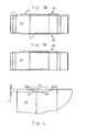
- the cutting inserts shown in the figures uniformly have a clamping surface 20 and a support surface 21 and respective open spaces 22, wherein the cutting inserts can also be designed as double-sided insert, ie, that the support surface 21 can also serve as rake face and vice versa, as shown in FIG 3a, 12 and 14-18.
- a mounting hole 23 is provided for receiving a clamping screw.
- the cutting plate in the region of the acute-angled corners 24 according to the invention designed such that in a central region 25 of the cutting corners, which extends in the present case over an angle ⁇ ⁇ 90 °, uniformly convex rounded.
- This region 25 has a radius of curvature R 1 in the above-described order of magnitude.
- the cutting edge regions 26 are also convexly curved and have a radius R 2 which is greater than the aforementioned radius R 1 .
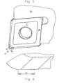
- the cutting edge is lowered in a portion of the length b s (see FIG. 6), which is located substantially in the region in which the cutting edge has a radius of curvature R 2 .
- the subsidence extends to some extent into the central cutting edge area with the radius of curvature R 1 .
- the cutting edge lowering over the area b s acts as a flattening of the cutting edge, which cuts a surface with low waviness during Zerspanungsoperationen ,
- FIGS. 7 to 9 show a corresponding cutting insert, which differs from the cutting insert described above only differs in that he is under a positive Free angle arranged open spaces 22 has.
- the same Way running cutting edge reduction leads to the same here Results when the cutting insert in a 0 ° or positive mounting position is embedded in a holder.
- the cutting insert according to FIGS. 10 to 13 is designed in the cutting edge region such that transition regions 27 with a convex radius R 4 adjoin the central cutting corner region with a radius R 1 on both sides and a respective concave cutting edge region 28 is connected thereto a small transition region 29 merges with the aforementioned radius R 4 in the continuation of the cutting edge.
- the cutting edge is viewed in a side view of FIG. 13 in addition to the distance h shown in Fig. 13 raised so that in a directed to the open space side view a convex cutting edge profile results.
- Figs. 14 to 17 show beyond that on the entire cutting edge length, but especially in the field of Cutting corners 24 a Spanformnut 30 is provided according to Fig. 16 from a sloping, forming a positive rake angle Flank 31 and rising edges 32 is formed.
- the Angle ⁇ and ⁇ show the installation position of the cutting insert in Holder, by the inclination of the bearing surface used is determined.
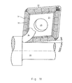
- Fig. 18 shows a cutting insert in a mounting position at Longitudinal turning of a workpiece 33 at a setting angle ⁇ (the minor cutting edge), which is between 2 ° and 10 °, preferably 4 ° and 6 °.
- the expiring span 34 is indicated schematically.
Landscapes
- Engineering & Computer Science (AREA)
- Mechanical Engineering (AREA)
- Cutting Tools, Boring Holders, And Turrets (AREA)
- Milling Processes (AREA)
- Gripping On Spindles (AREA)
- Surgical Instruments (AREA)
- Drilling Tools (AREA)
Description
- Fig. 1
- eine Draufsicht auf eine erfindungsgemäße rhombische Wendeschneidplatte,
- Fig. 2
- eine Teilansicht einer spitzwinkligen Schneidecke des Schneideinsatzes nach Fig. 1,
- Fig. 3a
- eine Seitenansicht eines doppelseitig verwendbaren Schneideinsatzes nach Fig. 1,
- Fig. 3b
- eine Seitenansicht eines einseitig verwendbaren Schneideinsatzes nach Fig. 1,
- Fig. 4
- eine Detailansicht des Schneidkantenverlaufes im Eckenbereich gemäß Fig. 3a,
- Fig. 5
- den nach Fig. 1 bis 4 dargestellten Schneideinsatz in einer schematischen Darstellung in seiner Einbaulage in einem Schneideinsatzhalter,
- Fig. 6
- eine Detailansicht einer Schneidecke gemäß Fig. 5,
- Fig. 7
- die Draufsicht auf einen rhombischen Schneideinsatz mit einer unter einem positiven Winkel geneigten Freifläche,
- Fig. 8
- eine Seitenansicht des Schneideinsatzes nach Fig. 7,
- Fig. 9
- eine Detailansicht der Schneidecke des Schneideinsatzes gemäß Fig. 8,
- Fig. 10
- eine Draufsicht auf einen rhombischen Schneideinsatz in einer weiteren Ausführungsform,
- Fig. 11
- eine Detailansicht des Schneideinsatzes nach Fig. 10 im Schneideckenbereich,
- Fig. 12
- eine Seitenansicht des Schneideinsatzes nach Fig. 10,
- Fig. 13
- eine Detailansicht des Schneideinsatzes nach Fig. 12,
- Fig. 14
- eine perspektivische Darstellung einer Wendeschneidplatte mit einer Spanformnut,
- Fig. 15
- die Wendeschneidplatte nach Fig. 14, dargestellt in ihrer Einbaulage,
- Fig. 16
- einen Schnitt entlang der Linie A - A in Fig. 15,
- Fig. 17
- einen Schnitt entlang der Linie B - B in Fig. 15 und
- Fig. 18
- eine Wendeschneidplatte gemäß Fig. 14 bis 17 in ihrer Einbaulage beim Längsdrehen.
Claims (10)
- Schneideinsatz für Zerspanungsarbeiten, insbesondere zum Plan- und Längsdrehen von Werkstücken (33), bestehend aus einem polygonalen Körper mit einer Spanfläche (20), einer hierzu beabstandeten Auflagefläche (21) sowie die Span- und die Auflagefläche verbindenden Freiflächen (22), wobei die Spanfläche (20) und die Freiflächen (22) jeweilige Schneidkanten bilden, und mit mindestens einer durch zwei Schneidkanten gebildeten abgerundeten Schneidecke (24), die - in einer Draufsicht auf die Spanfläche (20) betrachtet - einen mittleren Bereich (25) mit einem ersten Krümmungsradius (R1) und sich jeweils seitlich hieran anschließende zweite Bereiche (26) mit einem zweiten, größeren Krümmungsradius (R2) besitzt,
dadurch gekennzeichnet, daß mindestens eine der Schneidkanten im Abstand zu dem durch die Schneideckenwinkelhalbierenden bestimmten Schneideckenmittelpunkt, aber im abgerundeten Schneideckenbereich über einen Teilbereich (bs) abgesenkt ist. - Schneideinsatz nach Anspruch 1, dadurch gekennzeichnet, daß der erste Krümmungsradius (R1) 0,1 mm bis 2,4 mm, vorzugsweise 0,4 mm bis 1,6 mm, und der zweite Krümmungsradius (R2) 1 mm bis 28 mm, vorzugsweise 4 mm bis 19 mm, groß ist und/oder daß der größere Krümmungsradius (R2) zwischen dem 6fachen und dem 12fachen Wert des ersten Krümmungsradius (6 x R1 ≤ R2 ≤ 12 x R1) liegt.
- Schneideinsatz nach Anspruch 1 oder 2, dadurch gekennzeichnet, daß der Abstand (t), den der tiefste Punkt des abgesenkten Schneidkantenbereiches gegenüber dem Niveau benachbarter, außerhalb der Absenkung liegender Schneidkantenbereiche hat, zwischen 0,04 mm und 0,4 mm, vorzugsweise zwischen 0,1 mm und 0,2 mm, liegt und/oder daß der Bereich der Schneidkantenabsenkung stetig konkav gekrümmt verläuft und im wesentlichen in dem Bereich liegt, in dem die Schneidkante unter dem größeren Krümmungsradius (R2) verläuft, vorzugsweise dergestalt, daß ein Teil des abgesenkten Schneidkantenbereiches in dem mittleren Schneideckenbereich mit einem Krümmungsradius (R1) hineinreicht.
- Schneideinsatz nach einem der Ansprüche 1 bis 3, dadurch gekennzeichnet, daß der Schneideinsatz in einen Schneideinsatzhalter in einer negativen Einbaulage unter den Einbettungswinkeln (α) und (β), die 3° ≤ α ≤ 10° und 3° ≤ β ≤ 10°, vorzugsweise 5° ≤ α ≤ 8° und 5° ≤ β ≤ 8° betragen, angeordnet ist und/oder daß der Schneideinsatz unter einem positiven Winkel angeordnete Freiflächen aufweist und im Schneideinsatzhalter in einer 0°- oder einer Positiven Einbaulage angeordnet ist.
- Schneideinsatz für Zerspanungsarbeiten, insbesondere zum Plan- und Längsdrehen von Werkstücken (33), bestehend aus einem polygonalen Körper mit einer Spanfläche (20), einer hierzu beabstandeten Auflagefläche (21) sowie die Span- und die Auflagefläche verbindenden Freiflächen (22), wobei die Spanfläche (20) und die Freiflächen (22) jeweilige Schneidkanten bilden, und mit mindestens einer durch zwei Schneidkanten gebildeten gekrümmten Schneidecke mit mehreren, unterschiedliche Krümmungsradien aufweisenden Bereichen, dadurch gekennzeichnet, daß mindestens eine der Schneidkanten - in einer Draufsicht betrachtet - einen mittleren konvexen Schneideckenbereich mit einem ersten Radius (R1) und einer hierneben liegenden konkaven Schneidkantenbereich mit einem größeren Radius (R3) besitzt und daß der konkave Schneidkantenbereich zusätzlich angehoben ist, so daß die Schneidkante in diesem Bereich in einer Seitenansicht (auf die Freifläche) betrachtet konvex verläuft.
- Schneideinsatz nach Anspruch 5, dadurch gekennzeichnet, daß der Abstand (h), den der höchste Punkt des angehobenen Schneidkantenbereiches gegenüber dem Niveau benachbarter, nicht angehobener Schneidkantenbereiche hat, zwischen 0,04 mm und 0,4 mm, vorzugsweise zwischen 0,1 mm und 0,2 mm, liegt und/oder daß zwischen dem mittleren Schneideckenbereich und dem konkaven Schneidkantenbereich ein Schneidkantenübergangsbereich vorgesehen ist, der einen Krümmungsradius (R4) zwischen 0,1 mm bis 0,4 mm aufweist.
- Schneideinsatz nach einem der Ansprüche 1 bis 6, dadurch gekennzeichnet, daß die Schneidkanten spiegelsymmetrisch zur Schneideckenwinkelhalbierenden ausgebildet sind.
- Schneideinsatz nach einem der Ansprüche 1 bis 7, dadurch gekennzeichnet, daß der Schneideinsatz eine rhombische Form aufweist und die unterschiedlich gekrümmten Schneideckenbereiche in den gegenüberliegenden spitzwinkligen Schneidecken ausgebildet sind und/oder daß der abgesenkte oder der angehobene Schneidkantenbereich eine Länge (bs) zwischen 0,2 mm und 2,9 mm, vorzugsweise 0,4 mm und 1,2 mm, hat und/oder die Bedingung 0,4 R1 ≤ bs ≤ 1,2 R1 erfüllt.
- Schneideinsatz nach einem der Ansprüche 1 bis 8, dadurch gekennzeichnet, daß der sich senkrecht zur Schneidkante anschließende Spanflächenbereich eine abfallende Flanke aufweist, wobei die Flanke (31) Teil einer Spanformnut (30) ist, die sich parallel zu Schneidkante erstreckt.
- Schneideinsatz nach einem der Ansprüche 1 bis 9, dadurch gekennzeichnet, daß im Abstand zur Schneidkante erhaben ausgebildete Spanformelemente auf der Spanfläche angeordnet sind und/oder daß die Nebenschneide des Schneideinsatzes beim Zerspanen zum Werkstück unter einem Winkel2° ≤ κ ≤ 10°, vorzugsweise 4° ≤ κ ≤ 6° ausgerichtet ist.
Applications Claiming Priority (3)
| Application Number | Priority Date | Filing Date | Title |
|---|---|---|---|
| DE10018452 | 2000-04-13 | ||
| DE10018452A DE10018452A1 (de) | 2000-04-13 | 2000-04-13 | Schneideinsatz |
| PCT/DE2001/000674 WO2001078926A1 (de) | 2000-04-13 | 2001-02-20 | Schneideinsatz |
Publications (2)
| Publication Number | Publication Date |
|---|---|
| EP1272304A1 EP1272304A1 (de) | 2003-01-08 |
| EP1272304B1 true EP1272304B1 (de) | 2005-08-03 |
Family
ID=7638690
Family Applications (1)
| Application Number | Title | Priority Date | Filing Date |
|---|---|---|---|
| EP01915029A Expired - Lifetime EP1272304B1 (de) | 2000-04-13 | 2001-02-20 | Schneideinsatz |
Country Status (5)
| Country | Link |
|---|---|
| US (1) | US20030031520A1 (de) |
| EP (1) | EP1272304B1 (de) |
| AT (1) | ATE301018T1 (de) |
| DE (2) | DE10018452A1 (de) |
| WO (1) | WO2001078926A1 (de) |
Families Citing this family (28)
| Publication number | Priority date | Publication date | Assignee | Title |
|---|---|---|---|---|
| US6666118B2 (en) * | 2001-03-19 | 2003-12-23 | General Motors Corporation | Piston skirt turning tool and method |
| US7234899B2 (en) * | 2003-05-19 | 2007-06-26 | Tdy Industries, Inc. | Cutting tool having a wiper nose corner |
| US7220083B2 (en) | 2003-10-15 | 2007-05-22 | Tdy Industries, Inc. | Cutting insert for high feed face milling |
| AT500864B1 (de) * | 2004-06-02 | 2008-12-15 | Boehlerit Gmbh & Co Kg | Wendeschneidplatte für iso-klemmhalter |
| US7905687B2 (en) * | 2007-01-16 | 2011-03-15 | Tdy Industries, Inc. | Cutting insert, tool holder, and related method |
| SE531508C2 (sv) | 2007-08-31 | 2009-05-05 | Sandvik Intellectual Property | Skär för spånavskiljande bearbetning med ett avstrykningssegment |
| US7905689B2 (en) | 2008-05-07 | 2011-03-15 | Tdy Industries, Inc. | Cutting tool system, cutting insert, and tool holder |
| US8491234B2 (en) * | 2009-02-12 | 2013-07-23 | TDY Industries, LLC | Double-sided cutting inserts for high feed milling |
| US7976250B2 (en) * | 2009-02-12 | 2011-07-12 | Tdy Industries, Inc. | Double-sided cutting inserts for high feed milling |
| US9586264B2 (en) * | 2009-04-28 | 2017-03-07 | Kennametal Inc. | Double-sided cutting insert for drilling tool |
| US8807884B2 (en) * | 2009-12-18 | 2014-08-19 | Kennametal Inc. | Tool holder for multiple differently-shaped cutting inserts |
| US8887838B2 (en) * | 2010-02-05 | 2014-11-18 | Baker Hughes Incorporated | Cutting element and method of orienting |
| US8997899B2 (en) | 2010-02-05 | 2015-04-07 | Baker Hughes Incorporated | Cutting element, cutter tool and method of cutting within a borehole |
| JP2014512978A (ja) * | 2011-05-03 | 2014-05-29 | ダイヤモンド イノベイションズ インコーポレーテッド | 前縁部で切り屑を薄肉化するワイパー切れ刃を有するインサート |
| US9580970B2 (en) | 2012-06-22 | 2017-02-28 | Baker Hughes Incorporated | Cutting element, tool and method of cutting within a borehole |
| US9546520B2 (en) | 2012-06-22 | 2017-01-17 | Baker Hughes Incorporated | Cutting element, tool and method of cutting within a borehole |
| US9283626B2 (en) | 2012-09-25 | 2016-03-15 | Kennametal Inc. | Double-sided cutting inserts with anti-rotation features |
| US9011049B2 (en) | 2012-09-25 | 2015-04-21 | Kennametal Inc. | Double-sided cutting inserts with anti-rotation features |
| DE102014102173B4 (de) | 2013-03-22 | 2021-06-10 | Kennametal India Limited | Schneideinsatz mit einem linearen und einem konkaven schneidkantenabschnitt sowie bohrwerkzeug |
| US9724761B2 (en) | 2013-03-22 | 2017-08-08 | Kennametal India Limited | Cutting insert with a linear and a concave cutting edge portion |
| EP2805786B1 (de) * | 2013-05-21 | 2019-07-10 | Pramet Tools, S.R.O. | Indizierbarer Schneideinsatz mit Seitenabstütztal, und Fräswerkzeug |
| DE112016001367B4 (de) * | 2015-03-23 | 2023-08-17 | Kyocera Corporation | Einsatz, Bohrer und Verfahren des Herstellens eines maschinell bearbeiteten Produkts unter Verwendung derselben |
| JP6542975B2 (ja) * | 2016-02-24 | 2019-07-10 | 京セラ株式会社 | インサート、切削工具及び切削加工物の製造方法 |
| EP3260225B1 (de) * | 2016-06-20 | 2022-11-30 | Sandvik Intellectual Property AB | Dreheinsatz |
| US10919095B2 (en) * | 2016-07-11 | 2021-02-16 | Kyocera Corporation | Cutting insert, cutting tool, and method of manufacturing machined product |
| EP3476508A1 (de) * | 2017-10-31 | 2019-05-01 | Sandvik Intellectual Property AB | Dreheinsatz |
| US11529691B2 (en) * | 2019-12-02 | 2022-12-20 | Kennametal Inc. | Rotary cutting tool with hybrid cutting insert design |
| CN115551663B (zh) * | 2020-05-26 | 2025-11-25 | 京瓷株式会社 | 切削刀片、切削刀具以及切削加工物的制造方法 |
Family Cites Families (14)
| Publication number | Priority date | Publication date | Assignee | Title |
|---|---|---|---|---|
| US2424473A (en) * | 1945-11-08 | 1947-07-22 | John Milton Luers Patents Inc | Cutting-off blade |
| SE377771B (de) * | 1971-07-07 | 1975-07-28 | Sandvik Ab | |
| SE448431B (sv) * | 1985-07-03 | 1987-02-23 | Santrade Ltd | Vendsker for spanavskiljande bearbetning |
| US5203649A (en) * | 1991-10-07 | 1993-04-20 | Gte Valentine Corporation | High productivity, high metal removal rate insert |
| DE706433T1 (de) * | 1993-06-25 | 1996-10-24 | Kennametal Inc | Scheideinsatzeckengeometrie für verbesserten oberflächerauhigkeit |
| US5388932A (en) * | 1993-09-13 | 1995-02-14 | Kennametal Inc. | Cutting insert for a milling cutter |
| DE4411475A1 (de) * | 1994-04-01 | 1995-10-05 | Walter Ag | Schneidplatte, insbesondere Wendeschneidplatte |
| SE512253C2 (sv) * | 1997-06-30 | 2000-02-21 | Sandvik Ab | Vändskär |
| SE516735C2 (sv) * | 1998-06-05 | 2002-02-26 | Sandvik Ab | Vändskär för kopiersvarvning |
| SE519133C2 (sv) * | 1998-10-13 | 2003-01-21 | Sandvik Ab | Borrskär för metallborrning |
| JP2001212704A (ja) * | 2000-01-31 | 2001-08-07 | Ngk Spark Plug Co Ltd | スローアウェイチップ |
| US6540450B2 (en) * | 2000-11-29 | 2003-04-01 | Hayes Lemmerz International, Inc. | Tool and process for finishing a vehicle wheel surface |
| US6623217B2 (en) * | 2001-09-24 | 2003-09-23 | Valenite, Inc. | Indexable turning insert |
| SE523620C2 (sv) * | 2001-10-01 | 2004-05-04 | Sandvik Ab | Skär för spånavskiljande bearbetning med ytavstrykande eggsegment. |
-
2000
- 2000-04-13 DE DE10018452A patent/DE10018452A1/de not_active Withdrawn
-
2001
- 2001-02-20 WO PCT/DE2001/000674 patent/WO2001078926A1/de not_active Ceased
- 2001-02-20 DE DE50106976T patent/DE50106976D1/de not_active Expired - Fee Related
- 2001-02-20 AT AT01915029T patent/ATE301018T1/de not_active IP Right Cessation
- 2001-02-20 US US10/220,961 patent/US20030031520A1/en not_active Abandoned
- 2001-02-20 EP EP01915029A patent/EP1272304B1/de not_active Expired - Lifetime
Also Published As
| Publication number | Publication date |
|---|---|
| DE50106976D1 (de) | 2005-09-08 |
| WO2001078926A1 (de) | 2001-10-25 |
| US20030031520A1 (en) | 2003-02-13 |
| DE10018452A1 (de) | 2001-10-25 |
| ATE301018T1 (de) | 2005-08-15 |
| EP1272304A1 (de) | 2003-01-08 |
Similar Documents
| Publication | Publication Date | Title |
|---|---|---|
| EP1272304A1 (de) | Schneideinsatz | |
| DE69409364T2 (de) | Schneideinsatz mit spiralförmiger erhabener fläche und angrenzender ausnehmung | |
| DE69409365T2 (de) | Schneideinsatz mit spiralförmiger spanfläche | |
| DE60002186T2 (de) | Schneideinsatz | |
| DE69124953T2 (de) | Bohrwerkzeug und Einsatz dafür | |
| DE69503442T2 (de) | Schneideinsatz | |
| DE102006023740B4 (de) | Schneideinsatz und Werkzeug, bestehend aus Werkzeughalter und Schneideinsatz | |
| DE19901456B4 (de) | Wendeschneidplatte | |
| DE60305890T2 (de) | Tangentialschneideinsatz und schneideinsatzhalter | |
| DE69315472T2 (de) | Werkzeug zum Abschneiden oder ähnlichen Dreharbeiten | |
| DE10134636B4 (de) | Schneideinsatz mit radial ausgerichteten Spanbildungsnuten | |
| DE69719348T2 (de) | Fräser mit schneideinsatz | |
| DE69410238T2 (de) | Schneideinsatz mit spiralförmiger spanoberfläche | |
| DE69619378T2 (de) | Werkzeug für metallbearbeitung | |
| DE60021529T2 (de) | Schneideinsatz für drehbearbeitung | |
| EP1309418B1 (de) | Schneideinsatz | |
| WO1995007783A1 (de) | Schneideinsatz | |
| EP0673701B1 (de) | Reibahle | |
| DE69402200T2 (de) | Scheideinsatzeckengeometrie für verbesserte oberflächerauhigkeit | |
| WO1996035538A1 (de) | Schneideinsatz und fräswerkzeug | |
| EP1852200B1 (de) | Schneideinsatz zur spanabhebenden Bearbeitung | |
| EP0073926A1 (de) | Schneidwerkzeug, insbesondere Wendeschneidplatte | |
| EP1224992B1 (de) | Schneidwerkzeug und Wendeschneidplatte | |
| DE60019438T2 (de) | Schneideinsatz zum einstecken | |
| DE69409943T2 (de) | Schneideinsatz mit spiralförmiger erhabener fläche |
Legal Events
| Date | Code | Title | Description |
|---|---|---|---|
| PUAI | Public reference made under article 153(3) epc to a published international application that has entered the european phase |
Free format text: ORIGINAL CODE: 0009012 |
|
| 17P | Request for examination filed |
Effective date: 20020906 |
|
| AK | Designated contracting states |
Kind code of ref document: A1 Designated state(s): AT BE CH CY DE DK ES FI FR GB GR IE IT LI LU MC NL PT SE TR |
|
| AX | Request for extension of the european patent |
Free format text: AL;LT;LV;MK;RO;SI |
|
| RIN1 | Information on inventor provided before grant (corrected) |
Inventor name: HINTZE, WOLFGANG Inventor name: WUERFELS, ANDREAS |
|
| GRAP | Despatch of communication of intention to grant a patent |
Free format text: ORIGINAL CODE: EPIDOSNIGR1 |
|
| GRAS | Grant fee paid |
Free format text: ORIGINAL CODE: EPIDOSNIGR3 |
|
| GRAA | (expected) grant |
Free format text: ORIGINAL CODE: 0009210 |
|
| AK | Designated contracting states |
Kind code of ref document: B1 Designated state(s): AT BE CH CY DE DK ES FI FR GB GR IE IT LI LU MC NL PT SE TR |
|
| PG25 | Lapsed in a contracting state [announced via postgrant information from national office to epo] |
Ref country code: TR Free format text: LAPSE BECAUSE OF FAILURE TO SUBMIT A TRANSLATION OF THE DESCRIPTION OR TO PAY THE FEE WITHIN THE PRESCRIBED TIME-LIMIT Effective date: 20050803 Ref country code: FI Free format text: LAPSE BECAUSE OF FAILURE TO SUBMIT A TRANSLATION OF THE DESCRIPTION OR TO PAY THE FEE WITHIN THE PRESCRIBED TIME-LIMIT Effective date: 20050803 Ref country code: NL Free format text: LAPSE BECAUSE OF FAILURE TO SUBMIT A TRANSLATION OF THE DESCRIPTION OR TO PAY THE FEE WITHIN THE PRESCRIBED TIME-LIMIT Effective date: 20050803 Ref country code: IE Free format text: LAPSE BECAUSE OF FAILURE TO SUBMIT A TRANSLATION OF THE DESCRIPTION OR TO PAY THE FEE WITHIN THE PRESCRIBED TIME-LIMIT Effective date: 20050803 |
|
| REG | Reference to a national code |
Ref country code: GB Ref legal event code: FG4D Free format text: NOT ENGLISH |
|
| REG | Reference to a national code |
Ref country code: CH Ref legal event code: EP |
|
| GBT | Gb: translation of ep patent filed (gb section 77(6)(a)/1977) |
Effective date: 20050803 |
|
| REG | Reference to a national code |
Ref country code: IE Ref legal event code: FG4D Free format text: LANGUAGE OF EP DOCUMENT: GERMAN |
|
| REF | Corresponds to: |
Ref document number: 50106976 Country of ref document: DE Date of ref document: 20050908 Kind code of ref document: P |
|
| PG25 | Lapsed in a contracting state [announced via postgrant information from national office to epo] |
Ref country code: DK Free format text: LAPSE BECAUSE OF FAILURE TO SUBMIT A TRANSLATION OF THE DESCRIPTION OR TO PAY THE FEE WITHIN THE PRESCRIBED TIME-LIMIT Effective date: 20051103 Ref country code: GR Free format text: LAPSE BECAUSE OF FAILURE TO SUBMIT A TRANSLATION OF THE DESCRIPTION OR TO PAY THE FEE WITHIN THE PRESCRIBED TIME-LIMIT Effective date: 20051103 |
|
| PG25 | Lapsed in a contracting state [announced via postgrant information from national office to epo] |
Ref country code: ES Free format text: LAPSE BECAUSE OF FAILURE TO SUBMIT A TRANSLATION OF THE DESCRIPTION OR TO PAY THE FEE WITHIN THE PRESCRIBED TIME-LIMIT Effective date: 20051114 |
|
| REG | Reference to a national code |
Ref country code: SE Ref legal event code: TRGR |
|
| PG25 | Lapsed in a contracting state [announced via postgrant information from national office to epo] |
Ref country code: PT Free format text: LAPSE BECAUSE OF FAILURE TO SUBMIT A TRANSLATION OF THE DESCRIPTION OR TO PAY THE FEE WITHIN THE PRESCRIBED TIME-LIMIT Effective date: 20060103 |
|
| NLV1 | Nl: lapsed or annulled due to failure to fulfill the requirements of art. 29p and 29m of the patents act | ||
| PGFP | Annual fee paid to national office [announced via postgrant information from national office to epo] |
Ref country code: SE Payment date: 20060214 Year of fee payment: 6 |
|
| PGFP | Annual fee paid to national office [announced via postgrant information from national office to epo] |
Ref country code: FR Payment date: 20060216 Year of fee payment: 6 |
|
| PG25 | Lapsed in a contracting state [announced via postgrant information from national office to epo] |
Ref country code: AT Free format text: LAPSE BECAUSE OF NON-PAYMENT OF DUE FEES Effective date: 20060220 |
|
| PGFP | Annual fee paid to national office [announced via postgrant information from national office to epo] |
Ref country code: GB Payment date: 20060221 Year of fee payment: 6 |
|
| PG25 | Lapsed in a contracting state [announced via postgrant information from national office to epo] |
Ref country code: MC Free format text: LAPSE BECAUSE OF NON-PAYMENT OF DUE FEES Effective date: 20060228 Ref country code: LU Free format text: LAPSE BECAUSE OF NON-PAYMENT OF DUE FEES Effective date: 20060228 Ref country code: LI Free format text: LAPSE BECAUSE OF NON-PAYMENT OF DUE FEES Effective date: 20060228 Ref country code: CH Free format text: LAPSE BECAUSE OF NON-PAYMENT OF DUE FEES Effective date: 20060228 Ref country code: BE Free format text: LAPSE BECAUSE OF NON-PAYMENT OF DUE FEES Effective date: 20060228 |
|
| PGFP | Annual fee paid to national office [announced via postgrant information from national office to epo] |
Ref country code: IT Payment date: 20060228 Year of fee payment: 6 |
|
| REG | Reference to a national code |
Ref country code: IE Ref legal event code: FD4D |
|
| PGFP | Annual fee paid to national office [announced via postgrant information from national office to epo] |
Ref country code: DE Payment date: 20060426 Year of fee payment: 6 |
|
| ET | Fr: translation filed | ||
| PLBE | No opposition filed within time limit |
Free format text: ORIGINAL CODE: 0009261 |
|
| STAA | Information on the status of an ep patent application or granted ep patent |
Free format text: STATUS: NO OPPOSITION FILED WITHIN TIME LIMIT |
|
| 26N | No opposition filed |
Effective date: 20060504 |
|
| REG | Reference to a national code |
Ref country code: CH Ref legal event code: PL |
|
| PG25 | Lapsed in a contracting state [announced via postgrant information from national office to epo] |
Ref country code: SE Free format text: LAPSE BECAUSE OF NON-PAYMENT OF DUE FEES Effective date: 20070221 |
|
| EUG | Se: european patent has lapsed | ||
| GBPC | Gb: european patent ceased through non-payment of renewal fee |
Effective date: 20070220 |
|
| REG | Reference to a national code |
Ref country code: FR Ref legal event code: ST Effective date: 20071030 |
|
| BERE | Be: lapsed |
Owner name: WIDIA G.M.B.H. Effective date: 20060228 |
|
| PG25 | Lapsed in a contracting state [announced via postgrant information from national office to epo] |
Ref country code: DE Free format text: LAPSE BECAUSE OF NON-PAYMENT OF DUE FEES Effective date: 20070901 |
|
| PG25 | Lapsed in a contracting state [announced via postgrant information from national office to epo] |
Ref country code: FR Free format text: LAPSE BECAUSE OF NON-PAYMENT OF DUE FEES Effective date: 20070228 Ref country code: GB Free format text: LAPSE BECAUSE OF NON-PAYMENT OF DUE FEES Effective date: 20070220 |
|
| PG25 | Lapsed in a contracting state [announced via postgrant information from national office to epo] |
Ref country code: CY Free format text: LAPSE BECAUSE OF FAILURE TO SUBMIT A TRANSLATION OF THE DESCRIPTION OR TO PAY THE FEE WITHIN THE PRESCRIBED TIME-LIMIT Effective date: 20050803 |
|
| PG25 | Lapsed in a contracting state [announced via postgrant information from national office to epo] |
Ref country code: IT Free format text: LAPSE BECAUSE OF NON-PAYMENT OF DUE FEES Effective date: 20070220 |