EP1272002A2 - Microphone device for a behind the ear hearing aid - Google Patents
Microphone device for a behind the ear hearing aid Download PDFInfo
- Publication number
- EP1272002A2 EP1272002A2 EP02013819A EP02013819A EP1272002A2 EP 1272002 A2 EP1272002 A2 EP 1272002A2 EP 02013819 A EP02013819 A EP 02013819A EP 02013819 A EP02013819 A EP 02013819A EP 1272002 A2 EP1272002 A2 EP 1272002A2
- Authority
- EP
- European Patent Office
- Prior art keywords
- microphone
- hearing aid
- sound
- housing
- sound inlet
- Prior art date
- Legal status (The legal status is an assumption and is not a legal conclusion. Google has not performed a legal analysis and makes no representation as to the accuracy of the status listed.)
- Granted
Links
Images

Classifications
-
- H—ELECTRICITY
- H04—ELECTRIC COMMUNICATION TECHNIQUE
- H04R—LOUDSPEAKERS, MICROPHONES, GRAMOPHONE PICK-UPS OR LIKE ACOUSTIC ELECTROMECHANICAL TRANSDUCERS; DEAF-AID SETS; PUBLIC ADDRESS SYSTEMS
- H04R25/00—Deaf-aid sets, i.e. electro-acoustic or electro-mechanical hearing aids; Electric tinnitus maskers providing an auditory perception
- H04R25/40—Arrangements for obtaining a desired directivity characteristic
- H04R25/402—Arrangements for obtaining a desired directivity characteristic using contructional means
-
- H—ELECTRICITY
- H04—ELECTRIC COMMUNICATION TECHNIQUE
- H04R—LOUDSPEAKERS, MICROPHONES, GRAMOPHONE PICK-UPS OR LIKE ACOUSTIC ELECTROMECHANICAL TRANSDUCERS; DEAF-AID SETS; PUBLIC ADDRESS SYSTEMS
- H04R1/00—Details of transducers, loudspeakers or microphones
- H04R1/20—Arrangements for obtaining desired frequency or directional characteristics
- H04R1/32—Arrangements for obtaining desired frequency or directional characteristics for obtaining desired directional characteristic only
- H04R1/34—Arrangements for obtaining desired frequency or directional characteristics for obtaining desired directional characteristic only by using a single transducer with sound reflecting, diffracting, directing or guiding means
- H04R1/342—Arrangements for obtaining desired frequency or directional characteristics for obtaining desired directional characteristic only by using a single transducer with sound reflecting, diffracting, directing or guiding means for microphones
-
- H—ELECTRICITY
- H04—ELECTRIC COMMUNICATION TECHNIQUE
- H04R—LOUDSPEAKERS, MICROPHONES, GRAMOPHONE PICK-UPS OR LIKE ACOUSTIC ELECTROMECHANICAL TRANSDUCERS; DEAF-AID SETS; PUBLIC ADDRESS SYSTEMS
- H04R1/00—Details of transducers, loudspeakers or microphones
- H04R1/20—Arrangements for obtaining desired frequency or directional characteristics
- H04R1/32—Arrangements for obtaining desired frequency or directional characteristics for obtaining desired directional characteristic only
- H04R1/34—Arrangements for obtaining desired frequency or directional characteristics for obtaining desired directional characteristic only by using a single transducer with sound reflecting, diffracting, directing or guiding means
- H04R1/38—Arrangements for obtaining desired frequency or directional characteristics for obtaining desired directional characteristic only by using a single transducer with sound reflecting, diffracting, directing or guiding means in which sound waves act upon both sides of a diaphragm and incorporating acoustic phase-shifting means, e.g. pressure-gradient microphone
-
- H—ELECTRICITY
- H04—ELECTRIC COMMUNICATION TECHNIQUE
- H04R—LOUDSPEAKERS, MICROPHONES, GRAMOPHONE PICK-UPS OR LIKE ACOUSTIC ELECTROMECHANICAL TRANSDUCERS; DEAF-AID SETS; PUBLIC ADDRESS SYSTEMS
- H04R25/00—Deaf-aid sets, i.e. electro-acoustic or electro-mechanical hearing aids; Electric tinnitus maskers providing an auditory perception
- H04R25/60—Mounting or interconnection of hearing aid parts, e.g. inside tips, housings or to ossicles
- H04R25/604—Mounting or interconnection of hearing aid parts, e.g. inside tips, housings or to ossicles of acoustic or vibrational transducers
Definitions
- the invention relates to a hearing aid that can be worn behind the ear with a hearing aid housing and one in the hearing aid housing arranged microphone with a microphone housing.
- Known microphones provide a microphone body, which with a nozzle-shaped microphone inlet is connected. This Sound inlet connection is in a corresponding recording in the Hearing aid housing introduced, the sound inlet connector for acoustic and mechanical reasons mostly immediately through the housing surface to the sound inlet opening in the Hearing aid housing leads.
- the hearing aid has a first Microphone on another microphone that is only for near-sound sensitive and coupled to a second input of the amplifier is, both microphones with the assigned Inputs of the amplifier are coupled that when fed the output signals of the two microphones to the respective Inputs of the amplifier the amplifier almost no output signal provides, provided the output signals of the two Microphones are caused by near-sound.
- From DE 198 52 758 C2 is a wearable behind the ear Hearing aid with one connected to an amplifier circuit Microphone system known. Through one to the vertical can be swiveled and / or rotated horizontally in or Carrier for the microphone system arranged on the hearing aid device, that at least one microphone and two sound inlet openings is the recording characteristic of the microphone system variable.
- WO 00/49836 describes a microphone for arrangement in known a hearing aid, the microphone three sound inlet openings has, all in a common level are arranged.
- the object of the present invention is the arrangement of a Microphones with a microphone housing in one behind the Improve ear portable hearing aid.
- This task is performed with a hearing aid that can be worn behind the ear with a hearing aid housing and one in the hearing aid housing arranged microphone with a microphone housing thereby solved that the hearing aid housing in opposite sides each has a sound inlet opening and two opposite ones A sound inlet connector on each side of the microphone housing arranged with a sound inlet opening is, the sound inlet connection in the sound inlet openings of the hearing aid housing protrude and being worn Hearing aid at least approximately the sound entry opening of a sound inlet connector distal and the sound inlet opening of the other sound inlet connection is arranged proximal to the head of a hearing aid wearer.
- the hearing aid designed according to the invention enables on simple arrangement of lateral sound inlet openings in the hearing aid housing. Due to the small design of the microphone as well as the elimination of additional sound conduction channels between the microphone and the sound inlet opening in the hearing aid housing is the placement of the microphone in both the middle as well as at one end within the hearing aid housing possible.
- the one-sided inlet of the acoustic Signals in the directly on the microphone membrane front microphone volume has the proposed Arrangement of a microphone with two sound inlets. This are arranged on two opposite microphone sides and also give the incident sound signals access to the front microphone volume.
- Microphones with opposing sound inlets can be easily integrated into the hearing aid housing and allow both sides with minimal space requirements Sound entry.
- the one required for physical reasons Cross-section of the sound entry surface is thus on the two Sound inlet nozzle distributed, which makes them proportional can be made small.
- the sound channels between the side sound entry openings in the hearing aid housing and the microphone membrane are according to the microphone the invention very short and simple, which is advantageous affects the acoustic properties.
- Farther can the sound inlet connection according to a microphone the invention in an advantageous manner as Means for attaching the microphone in the hearing aid. Further Fasteners can be omitted. So will through the microphone according to the invention both acoustic and design specifications also taken into account.
- the Sound inlet connection of the microphone as well as the sound inlet openings in opposite sides of the hearing aid housing arranged on a common axis of symmetry.
- a directional microphone system By arranging several microphones in the hearing aid and one A directional microphone system can provide suitable electrical wiring will be realized. All microphones are preferred designed according to the invention.
- the simple space-saving Housing a microphone according to the invention in the housing
- the hearing aid facilitates the placement of several of these Microphones inside a hearing aid housing.
- the microphone comprises several pairs of sound inlet connectors, where the sound inlet connection of each Pair on two opposite sides of the microphone housing are arranged and in a chamber on one side of a microphone membrane lead.
- the sound inlets are here of a pair in one sound entry opening in opposite Sides of the hearing aid housing introduced, with worn hearing aid at least approximately the sound entry opening of a sound inlet connector distal and the sound inlet opening of the other sound inlet connection a pair is located proximal to the head.
- a microphone according to the invention at least two pairs of sound inlet connectors a differential microphone form, which has a directional characteristic.
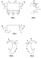
- Figures 4 and 5 show side views of one behind the Ear portable hearing aid according to the arrangement of a microphone the invention.
- FIG. 6 shows a hearing aid that can be worn behind the ear Section with a microphone arranged according to the invention.
- Figure 7 shows a microphone in cross section.
- Figure 1 shows a microphone 1 in plan view.
- the microphone 1 has a microphone housing 2, on the two opposite A sound inlet connection 3 or 4 is arranged on each side is.
- the sound inlet connection 3 and 4 form on their free end each a sound entry opening 3A or 4A and lead through the other end to a microphone chamber inside of the microphone 1.
- the microphone 1 comprises three Contacts 5, 6 and 7.
- Figure 2 shows the microphone 1 in a side view.
- the housing 2 To the Housing 2 is the one pointing out from the drawing level Sound inlet connection 3 with the sound inlet opening 3A arranged. Furthermore, the drawing is the electrical connection contact 5 removable.
- FIG. 1 An end face of the microphone 1 is shown in FIG. This is also the case 2 with the two, on opposite Sound inlet ports 3 and 4 arranged on the sides seen.
- FIG. 4 and 5 is a side view of one behind wearable hearing aid 8 shown.
- the hearing aid 8 comprises a hearing aid housing 9, at its upper end Support hook 10 is integrally formed.
- On two opposite sides of the housing the hearing aid housing 9 each has a sound inlet opening 11 or 12, in which the sound inlet connection introduced for recording the microphone according to the invention are. Due to the space-saving arrangement of the microphone of the invention in the hearing aid housing 9, the sound entry openings 11 and 12 almost arbitrarily on two opposite Sides of the hearing aid housing 9 are positioned.
- the sound inlet openings 11 and 12 are preferably located and thus the sound inlet connection of the microphone in question on a common axis.
- FIG. 6 shows a section in a simplified representation through the hearing aid housing 9.
- Two opposite housing shells 9A and 9B each have a sound inlet opening 11 or 12 on the two housing bushings 11A or 12A are formed.
- the microphone 1 is on both sides of the sound inlet connection 3 and 4 worn, the form-fitting in the two Housing bushings 11A and 12A are used.
- the microphone 1 also has the electrical Contacts 5, 6 and 7 open. From Figure 6 very space-saving accommodation of the microphone 1 inside of the hearing aid housing can be seen.
- the microphone holder takes place by means of the two sound inlet connections 3 and 4. This enables quick and easy assembly.
- Farther 6 are the very short sound transmission paths from the sound inlet openings 11 and 12 to the inside the microphone 1 can be removed. This has a positive effect on the acoustic properties of the hearing aid microphone unit out.
- FIG. 7 shows a microphone 13 in a schematic representation Cross-section.
- the Sound inlet stubs 15 to 18 form sound inlet openings 19 to 22.
- the sound inlet stubs 15 and 16 on one side of a microphone membrane 23 and the Sound inlet connection 17 and 18 on the opposite Side of the microphone membrane 23.
- the sound inlet connection 15 and 16 or 17 and 18 along a pair of sound inlets a common line of symmetry 24A and 24B arranged. So it is possible that through a sound inlet 19, 20, 21, 22 entering moisture or Soiling on the other side or can be blown out.
- a microphone with a microphone housing for placement in a hearing aid worn behind the ear with a hearing aid housing on two opposite On the sides of the microphone housing with a sound inlet connection arranged a sound inlet.
- the sound inlet connection open into a chamber on one side of the microphone membrane, where the sound inlet connection in one recording inserted in opposite sides of the hearing aid housing are and at least approximately when the hearing aid is worn the sound inlet opening of a sound inlet nozzle distal and the other's sound inlet Sound inlet connector is arranged proximal to the head.
Abstract
Description
Die Erfindung betrifft ein hinter dem Ohr tragbares Hörgerät mit einem Hörgerätegehäuse und einem in dem Hörgerätegehäuse angeordneten Mikrofon mit einem Mikrofongehäuse.The invention relates to a hearing aid that can be worn behind the ear with a hearing aid housing and one in the hearing aid housing arranged microphone with a microphone housing.
Bei der Entwicklung von Hörgeräten wird besonderes Augenmerk auf die Miniaturisierung gelegt. Insbesondere spielen bei modernen Hörgeräten die Mikrofone eine entscheidende Rolle, da bei Richtmikrofonanordnungen oft mehrere Einzelmikrofone in die Hörgeräte integriert werden müssen. Zudem ist die Position der Mikrofone häufig aus akustischen Gründen vorgegeben, so dass durch die Anordnung der Mikrofone schnell die Grenzen der Miniaturisierbarkeit erreicht sind und das Design der Hörgeräte vorgegeben ist.Particular attention is paid to the development of hearing aids placed on miniaturization. Especially play with modern ones Hearing aids the microphones play a crucial role there with directional microphone arrangements often several individual microphones in the hearing aids need to be integrated. In addition, the position the microphones are often specified for acoustic reasons, so that the arrangement of the microphones quickly limits the miniaturizability and the design of the Hearing aids is predetermined.
Bekannte Mikrofone sehen einen Mikrofonkorpus vor, der mit einem stutzenförmigen Mikrofoneinlass verbunden ist. Dieser Schalleintrittsstutzen wird in eine entsprechende Aufnahme im Hörgerätegehäuse eingeführt, wobei der Schalleintrittsstutzen aus akustischen und mechanischen Gründen meist unmittelbar durch die Gehäuseoberfläche zur Schalleintrittsöffnung im Hörgerätegehäuse führt.Known microphones provide a microphone body, which with a nozzle-shaped microphone inlet is connected. This Sound inlet connection is in a corresponding recording in the Hearing aid housing introduced, the sound inlet connector for acoustic and mechanical reasons mostly immediately through the housing surface to the sound inlet opening in the Hearing aid housing leads.
Aus der DE 296 21 611 U1 ist ein Mikrofon für ein elektrisches Hörgerät bekannt, das mit einem Schalleintrittsstutzen versehen ist.From DE 296 21 611 U1 is a microphone for an electrical Known hearing aid with a sound inlet connector is provided.
Aus der DE 689 14 083 T2 ist ein Hörgerät mit Pfeifunterdrückung bekannt. Hierzu weist das Hörgerät neben einem ersten Mikrofon ein weiteres Mikrofon auf, das nur für Nah-Schall empfindlich und mit einem zweiten Eingang des Verstärkers gekoppelt ist, wobei beide Mikrofone derart mit den zugeordneten Eingängen des Verstärkers gekoppelt sind, dass bei Zufuhr der Ausgangssignale der beiden Mikrofone zu den betreffenden Eingängen des Verstärkers der Verstärker nahezu kein Ausgangssignal liefert, sofern die Ausgangssignale der beiden Mikrofone durch Nah-Schall verursacht werden.DE 689 14 083 T2 describes a hearing aid with whistle suppression known. For this purpose, the hearing aid has a first Microphone on another microphone that is only for near-sound sensitive and coupled to a second input of the amplifier is, both microphones with the assigned Inputs of the amplifier are coupled that when fed the output signals of the two microphones to the respective Inputs of the amplifier the amplifier almost no output signal provides, provided the output signals of the two Microphones are caused by near-sound.
Aus der DE 198 52 758 C2 ist ein hinter dem Ohr tragbares Hörhilfegerät mit einem an eine Verstärkerschaltung angeschlossenen Mikrofonsystem bekannt. Durch einen zur Vertikalen schwenkbar und/oder in der Horizontalen drehbar im oder am Hörhilfegerät angeordneten Träger für das Mikrofonsystem, das wenigstens ein Mikrofon und zwei Schalleintrittsöffnungen umfasst, ist die Aufnahmecharakteristik des Mikrofonsystems veränderbar.From DE 198 52 758 C2 is a wearable behind the ear Hearing aid with one connected to an amplifier circuit Microphone system known. Through one to the vertical can be swiveled and / or rotated horizontally in or Carrier for the microphone system arranged on the hearing aid device, that at least one microphone and two sound inlet openings is the recording characteristic of the microphone system variable.
Ferner ist aus der WO 00/49836 ein Mikrofon zur Anordnung in einem Hörgerät bekannt, wobei das Mikrofon drei Schalleintrittsöffnungen aufweist, die alle in einer gemeinsamen Ebene angeordnet sind.Furthermore, WO 00/49836 describes a microphone for arrangement in known a hearing aid, the microphone three sound inlet openings has, all in a common level are arranged.
Aufgabe der vorliegenden Erfindung ist es, die Anordnung eines Mikrofons mit einem Mikrofongehäuse in einem hinter dem Ohr tragbaren Hörgerät zu verbessern.The object of the present invention is the arrangement of a Microphones with a microphone housing in one behind the Improve ear portable hearing aid.
Diese Aufgabe wird bei einem hinter dem Ohr tragbaren Hörgerät mit einem Hörgerätegehäuse und einem in dem Hörgerätegehäuse angeordneten Mikrofon mit einem Mikrofongehäuse dadurch gelöst, dass das Hörgerätegehäuse in gegenüberliegenden Seiten je eine Schalleintrittsöffnung aufweist und an zwei gegenüberliegenden Seiten des Mikrofongehäuses je ein Schalleintrittsstutzen mit einer Schalleintrittsöffnung angeordnet ist, wobei die Schalleintrittsstutzen in die Schalleintrittsöffnungen des Hörgerätegehäuses hineinragen und wobei bei getragenem Hörgerät zumindest näherungsweise die Schalleintrittsöffnung des einen Schalleintrittsstutzens distal und die Schalleintrittsöffnung des anderen Schalleintrittsstutzens proximal zum Kopf eines Hörgeräteträgers angeordnet ist. This task is performed with a hearing aid that can be worn behind the ear with a hearing aid housing and one in the hearing aid housing arranged microphone with a microphone housing thereby solved that the hearing aid housing in opposite sides each has a sound inlet opening and two opposite ones A sound inlet connector on each side of the microphone housing arranged with a sound inlet opening is, the sound inlet connection in the sound inlet openings of the hearing aid housing protrude and being worn Hearing aid at least approximately the sound entry opening of a sound inlet connector distal and the sound inlet opening of the other sound inlet connection is arranged proximal to the head of a hearing aid wearer.
Das gemäß der Erfindung ausgebildete Hörgerät ermöglicht auf einfache Weise die Anordnung seitlicher Schalleintrittsöffnungen im Hörgerätegehäuse. Durch die kleine Bauform des Mikrofons sowie den Wegfall zusätzlicher Schallleitungskanäle zwischen dem Mikrofon und der Schalleintrittsöffnung im Hörgerätegehäuse ist die Unterbringung des Mikrofons sowohl in der Mitte als auch an einem Ende innerhalb des Hörgerätegehäuses möglich. Im Gegensatz zu den bisher verwendeten Mikrofonen, die über einen einseitigen Einlass der akustischen Signale in das unmittelbar an der Mikrofonmembran liegende vordere Mikrofonvolumen verfügen, besitzt die vorgeschlagene Anordnung ein Mikrofon mit zwei Schalleintrittsstutzen. Diese sind an zwei entgegengesetzten Mikrofonseiten angeordnet und geben ebenso den einfallenden Schallsignalen Zugang zu dem vorderen Mikrofonvolumen.The hearing aid designed according to the invention enables on simple arrangement of lateral sound inlet openings in the hearing aid housing. Due to the small design of the microphone as well as the elimination of additional sound conduction channels between the microphone and the sound inlet opening in the hearing aid housing is the placement of the microphone in both the middle as well as at one end within the hearing aid housing possible. In contrast to the microphones used so far, the one-sided inlet of the acoustic Signals in the directly on the microphone membrane front microphone volume, has the proposed Arrangement of a microphone with two sound inlets. This are arranged on two opposite microphone sides and also give the incident sound signals access to the front microphone volume.
Mikrofone mit gegenüberliegenden Schalleintrittsstutzen können in einfacher Weise in Hörgerätegehäuse integriert werden und erlauben bei minimiertem Raumbedarf einen beidseitigen Schalleintritt. Der aus physikalischen Gründen erforderliche Querschnitt der Schalleintrittsfläche ist somit auf die beiden Schalleintrittsstutzen verteilt, wodurch diese verhältnismäßig klein ausgeführt sein können. Die Schallkanäle zwischen den seitlichen Schalleintrittsöffnungen im Hörgerätegehäuse und der Mikrofonmembran sind durch das Mikrofon gemäß der Erfindung sehr kurz und einfach ausgeführt, was sich vorteilhaft auf die akustischen Eigenschaften auswirkt. Weiterhin können die Schalleintrittsstutzen bei einem Mikrofon gemäß der Erfindung in vorteilhafter Weise gleichzeitig als Mittel zur Befestigung des Mikrofons im Hörgerät dienen. Weitere Befestigungsmittel können dadurch entfallen. So wird durch das Mikrofon gemäß der Erfindung sowohl akustischen als auch Designvorgaben Rechnung getragen.Microphones with opposing sound inlets can can be easily integrated into the hearing aid housing and allow both sides with minimal space requirements Sound entry. The one required for physical reasons Cross-section of the sound entry surface is thus on the two Sound inlet nozzle distributed, which makes them proportional can be made small. The sound channels between the side sound entry openings in the hearing aid housing and the microphone membrane are according to the microphone the invention very short and simple, which is advantageous affects the acoustic properties. Farther can the sound inlet connection according to a microphone the invention in an advantageous manner as Means for attaching the microphone in the hearing aid. Further Fasteners can be omitted. So will through the microphone according to the invention both acoustic and design specifications also taken into account.
Bei einer bevorzugten Ausführungsform der Erfindung sind die Schalleintrittsstutzen des Mikrofons sowie die Schalleintrittsöffnungen in gegenüberliegenden Seiten des Hörgerätegehäuses auf einer gemeinsamen Symmetrieachse angeordnet. Durch den so erreichten symmetrischen Aufbau des Mikrofongehäuses vereinfacht sich der Einbau sowie die Ausrichtung im Hörgerätegehäuse. Ferner können durch die eine Schalleintrittsöffnung eintretende Feuchtigkeit oder Verschmutzung durch die gegenüberliegende Schalleintrittsöffnung wieder austreten oder ggf. ausgeblasen werden.In a preferred embodiment of the invention, the Sound inlet connection of the microphone as well as the sound inlet openings in opposite sides of the hearing aid housing arranged on a common axis of symmetry. By the symmetrical construction of the microphone housing achieved in this way Installation and alignment in the hearing aid housing are simplified. Furthermore, through the one sound inlet opening incoming moisture or pollution from the exit the opposite sound inlet opening or may be blown out.
Durch die Anordnung mehrerer Mikrofone im Hörgerät sowie eine geeignete elektrische Verschaltung kann ein Richtmikrofonsystem realisiert werden. Bevorzugt sind dabei alle Mikrofone gemäß der Erfindung ausgestaltet. Die einfache platzsparende Unterbringung eines Mikrofons gemäß der Erfindung im Gehäuse des Hörgerätes erleichtert die Unterbringung mehrerer derartiger Mikrofone innerhalb eines Hörgerätegehäuses.By arranging several microphones in the hearing aid and one A directional microphone system can provide suitable electrical wiring will be realized. All microphones are preferred designed according to the invention. The simple space-saving Housing a microphone according to the invention in the housing The hearing aid facilitates the placement of several of these Microphones inside a hearing aid housing.
Eine andere Möglichkeit zur Realisierung eines Richtmikrofons besteht darin, ein einzelnes Mikrofon gemäß der Erfindung so weiterzubilden, dass dieses eine Richtwirkung aufweist. Hierzu umfasst das Mikrofon mehrere Paare von Schalleintrittsstutzen, wobei jeweils die Schalleintrittsstutzen eines Paares an zwei gegenüberliegenden Seiten des Mikrofongehäuses angeordnet sind und in eine Kammer auf einer Seite einer Mikrofonmembran münden. Dabei sind die Schalleintrittsstutzen eines Paares in je eine Schalleintrittsöffnung in gegenüberliegenden Seiten des Hörgerätegehäuses eingeführt, wobei bei getragenem Hörgerät zumindest näherungsweise die Schalleintrittsöffnung des einen Schalleintrittsstutzens distal und die Schalleintrittsöffnung des anderen Schalleintrittsstutzens eines Paares proximal zum Kopf angeordnet ist. Auf diese Weise lässt sich mit einem Mikrofon gemäß der Erfindung mit wenigstens zwei Paaren von Schalleintrittsstutzen ein Differenzmikrofon bilden, welches eine Richtcharakteristik aufweist. Another way of realizing a directional microphone consists of a single microphone according to the invention to further develop that this has a directivity. For this the microphone comprises several pairs of sound inlet connectors, where the sound inlet connection of each Pair on two opposite sides of the microphone housing are arranged and in a chamber on one side of a microphone membrane lead. The sound inlets are here of a pair in one sound entry opening in opposite Sides of the hearing aid housing introduced, with worn hearing aid at least approximately the sound entry opening of a sound inlet connector distal and the sound inlet opening of the other sound inlet connection a pair is located proximal to the head. To this Way can be with a microphone according to the invention at least two pairs of sound inlet connectors a differential microphone form, which has a directional characteristic.
Weitere Einzelheiten der Erfindung werden nachfolgend anhand von Ausführungsbeispielen näher erläutert. Dabei zeigen die Figuren 1 bis 3 ein Mikrofon in drei Seitenansichten.Further details of the invention are described below of exemplary embodiments explained in more detail. The show Figures 1 to 3 a microphone in three side views.
Die Figuren 4 und 5 zeigen Seitenansichten eines hinter dem Ohr tragbaren Hörgerätes zur Anordnung eines Mikrofons gemäß der Erfindung.Figures 4 and 5 show side views of one behind the Ear portable hearing aid according to the arrangement of a microphone the invention.
Figur 6 zeigt ein hinter dem Ohr tragbares Hörgerät im Schnitt mit einem gemäß der Erfindung angeordneten Mikrofon.FIG. 6 shows a hearing aid that can be worn behind the ear Section with a microphone arranged according to the invention.
Figur 7 zeigt ein Mikrofon im Querschnitt.Figure 7 shows a microphone in cross section.
Figur 1 zeigt ein Mikrofon 1 in Draufsicht. Das Mikrofon 1
weist ein Mikrofongehäuse 2 auf, an dem an zwei gegenüberliegenden
Seiten je ein Schalleintrittsstutzen 3 bzw. 4 angeordnet
ist. Die Schalleintrittsstutzen 3 und 4 bilden an ihrem
freien Ende je eine Schalleintrittsöffnung 3A bzw. 4A und
führen über ihr anderes Ende zu einer Mikrofonkammer im Inneren
des Mikrofons 1. Zum elektrischen Anschluss des Mikrofons
1 an einen Hörgeräteverstärker umfasst das Mikrofon 1 drei
Anschlusskontakte 5, 6 und 7.Figure 1 shows a
Figur 2 zeigt das Mikrofon 1 in einer Seitenansicht. An dem
Gehäuse 2 ist der aus der Zeichenebene herausweisende
Schalleintrittsstutzen 3 mit der Schalleintrittsöffnung 3A
angeordnet. Weiterhin ist der Zeichnung der elektrische Anschlusskontakt
5 entnehmbar.Figure 2 shows the
In Figur 3 ist eine Stirnseite des Mikrofons 1 abgebildet.
Auch daraus ist das Gehäuse 2 mit den beiden, an gegenüberliegenden
Seiten angeordneten Schalleintrittsstutzen 3 und 4
ersichtlich.An end face of the
In den Figuren 4 und 5 ist je eine Seitenansicht eines hinter
dem Ohr tragbaren Hörgerätes 8 dargestellt. Das Hörgerät 8
umfasst ein Hörgerätegehäuse 9, an dessen oberem Ende ein
Traghaken 10 angeformt ist. An zwei gegenüberliegenden Gehäuseseiten
weist das Hörgerätegehäuse 9 je eine Schalleintrittsöffnung
11 bzw. 12 auf, in die die Schalleintrittsstutzen
zur Aufnahme des Mikrofons gemäß der Erfindung eingeführt
sind. Durch die platzsparende Anordnung des Mikrofons gemäß
der Erfindung im Hörgerätegehäuse 9 können die Schalleintrittsöffnungen
11 und 12 nahezu beliebig an zwei gegenüberliegenden
Seiten des Hörgerätegehäuses 9 positioniert werden.
Vorzugsweise liegen die Schalleintrittsöffnungen 11 und 12
und damit die Schalleintrittsstutzen des betreffenden Mikrofons
auf einer gemeinsamen Achse.In Figures 4 and 5 is a side view of one behind
Figur 6 zeigt in vereinfachter Darstellung einen Schnitt
durch das Hörgerätegehäuse 9. Zwei gegenüberliegende Gehäuseschalen
9A und 9B weisen je eine Schalleintrittsöffnung 11
bzw. 12 auf, die von den beiden Gehäusedurchführungen 11A
bzw. 12A gebildet werden. In die Schalleintrittsöffnungen 11
bzw. 12 ragen die Schalleintrittsstutzen 3 bzw. 4 des Mikrofons
1. So wird das Mikrofon 1 beidseitig an den Schalleintrittsstutzen
3 und 4 getragen, die formschlüssig in die beiden
Gehäusedurchführungen 11A bzw. 12A eingesetzt sind. Durch
diese Anordnung ist das Mikrofon 1 schwenkbar im Hörgerätegehäuse
9 gelagert. Das Mikrofon 1 weist weiterhin die elektrischen
Anschlusskontakte 5, 6 und 7 auf. Aus Figur 6 wird die
sehr platzsparende Unterbringung des Mikrofons 1 innerhalb
des Hörgerätegehäuses ersichtlich. Die Halterung des Mikrofons
erfolgt mittels der beiden Schalleintrittsstutzen 3 und
4. Dies ermöglicht eine schnelle und einfache Montage. Weiterhin
sind der Figur 6 die sehr kurzen Schallleitungsstrecken
von den Schalleintrittsöffnungen 11 und 12 ins Innere
des Mikrofons 1 entnehmbar. Dies wirkt sich positiv auf die
akustischen Eigenschaften der Hörgeräte- Mikrofon- Einheit
aus.Figure 6 shows a section in a simplified representation
through the
Figur 7 zeigt in schematischer Darstellung ein Mikrofon 13 im
Querschnitt. An zwei gegenüberliegenden Seiten des Mikrofongehäuses
14 ist das Schalleintrittsstutzen-Paar 15 und 16 sowie
das Schalleintrittsstutzen-Paar 17 und 18 angebracht. Die
Schalleintrittsstutzen 15 bis 18 bilden Schalleintrittsöffnungen
19 bis 22. Dabei münden die Schalleintrittsstutzen 15
und 16 auf einer Seite einer Mikrofonmembran 23 und die
Schalleintrittsstutzen 17 und 18 auf der gegenüberliegenden
Seite der Mikrofonmembran 23. Dadurch ist das Mikrofon 13 als
Differenzmikrofon ausgebildet. Wie aus der Zeichnung weiterhin
ersichtlich ist, sind die Schalleintrittsstutzen 15 und
16 bzw. 17 und 18 je eines Schalleintrittsstutzen-Paares entlang
einer gemeinsamen Symmetrielinie 24A bzw. 24B angeordnet.
So ist es möglich, dass eventuell durch eine Schalleintrittsöffnung
19, 20, 21, 22 eintretende Feuchtigkeit oder
Verschmutzungen auf der anderen Seite wieder austreten bzw.
ausgeblasen werden können.FIG. 7 shows a
Zusammenfassend sind bei einem Mikrofon mit einem Mikrofongehäuse zur Anordnung in einem hinter dem Ohr tragbaren Hörgerät mit einem Hörgerätegehäuse an zwei gegenüberliegenden Seiten des Mikrofongehäuses je ein Schalleintrittsstutzen mit einer Schalleintrittsöffnung angeordnet. Die Schalleintrittsstutzen münden in eine Kammer auf einer Seite der Mikrofonmembran, wobei die Schalleintrittsstutzen in je eine Aufnahme in gegenüberliegenden Seiten des Hörgerätegehäuses eingeführt sind und wobei bei getragenem Hörgerät zumindest näherungsweise die Schalleintrittsöffnung des einen Schalleintrittsstutzens distal und die Schalleintrittsöffnung des anderen Schalleintrittsstutzens proximal zum Kopf angeordnet ist. Das so ausgebildete Mikrofon ist platzsparend und einfach im Hörgerät anzuordnen.In summary, a microphone with a microphone housing for placement in a hearing aid worn behind the ear with a hearing aid housing on two opposite On the sides of the microphone housing with a sound inlet connection arranged a sound inlet. The sound inlet connection open into a chamber on one side of the microphone membrane, where the sound inlet connection in one recording inserted in opposite sides of the hearing aid housing are and at least approximately when the hearing aid is worn the sound inlet opening of a sound inlet nozzle distal and the other's sound inlet Sound inlet connector is arranged proximal to the head. The The microphone thus designed is space-saving and simple in the hearing aid to arrange.
Claims (4)
Applications Claiming Priority (2)
| Application Number | Priority Date | Filing Date | Title |
|---|---|---|---|
| DE10131214 | 2001-06-28 | ||
| DE10131214A DE10131214C1 (en) | 2001-06-28 | 2001-06-28 | Microphone arrangement in a hearing aid that can be worn behind the ear |
Publications (3)
| Publication Number | Publication Date |
|---|---|
| EP1272002A2 true EP1272002A2 (en) | 2003-01-02 |
| EP1272002A3 EP1272002A3 (en) | 2009-04-15 |
| EP1272002B1 EP1272002B1 (en) | 2009-12-02 |
Family
ID=7689785
Family Applications (1)
| Application Number | Title | Priority Date | Filing Date |
|---|---|---|---|
| EP02013819A Expired - Lifetime EP1272002B1 (en) | 2001-06-28 | 2002-06-21 | Microphone device for a behind the ear hearing aid |
Country Status (5)
| Country | Link |
|---|---|
| US (1) | US6724903B2 (en) |
| EP (1) | EP1272002B1 (en) |
| AT (1) | ATE450984T1 (en) |
| DE (2) | DE10131214C1 (en) |
| DK (1) | DK1272002T3 (en) |
Cited By (1)
| Publication number | Priority date | Publication date | Assignee | Title |
|---|---|---|---|---|
| EP2323422A1 (en) * | 2008-07-30 | 2011-05-18 | Funai Electric Co., Ltd. | Differential microphone |
Families Citing this family (6)
| Publication number | Priority date | Publication date | Assignee | Title |
|---|---|---|---|---|
| CN1891012B (en) * | 2003-12-05 | 2012-10-24 | 奥迪康有限公司 | Communication device with microphone |
| US7542580B2 (en) * | 2005-02-25 | 2009-06-02 | Starkey Laboratories, Inc. | Microphone placement in hearing assistance devices to provide controlled directivity |
| US8121320B2 (en) * | 2008-01-11 | 2012-02-21 | Songbird Hearing, Inc. | Hearing aid |
| US20110085685A1 (en) * | 2009-10-08 | 2011-04-14 | Victor Kingsun Wai | Sound Amp Ear Device with Ear Phone Jack |
| KR102008374B1 (en) * | 2012-08-03 | 2019-10-23 | 삼성전자주식회사 | Input device for portable terminal |
| JP7051684B2 (en) | 2015-12-15 | 2022-04-11 | メルク パテント ゲーエムベーハー | Esters containing aromatic groups as solvents for organic electronic formulations |
Citations (2)
| Publication number | Priority date | Publication date | Assignee | Title |
|---|---|---|---|---|
| DE2330082A1 (en) * | 1972-07-24 | 1974-02-14 | Gould Inc | HOER AID |
| DE19852758A1 (en) * | 1998-11-16 | 2000-05-25 | Siemens Audiologische Technik | Behind-the-ear hearing aid |
Family Cites Families (3)
| Publication number | Priority date | Publication date | Assignee | Title |
|---|---|---|---|---|
| NL8802516A (en) * | 1988-10-13 | 1990-05-01 | Philips Nv | HEARING AID WITH CIRCULAR SUPPRESSION. |
| DE29621611U1 (en) * | 1996-12-12 | 1997-02-27 | Siemens Audiologische Technik | Microphone, in particular for electrical hearing aids |
| US6151399A (en) * | 1996-12-31 | 2000-11-21 | Etymotic Research, Inc. | Directional microphone system providing for ease of assembly and disassembly |
-
2001
- 2001-06-28 DE DE10131214A patent/DE10131214C1/en not_active Expired - Fee Related
-
2002
- 2002-06-21 AT AT02013819T patent/ATE450984T1/en not_active IP Right Cessation
- 2002-06-21 DE DE50214032T patent/DE50214032D1/en not_active Expired - Lifetime
- 2002-06-21 EP EP02013819A patent/EP1272002B1/en not_active Expired - Lifetime
- 2002-06-21 DK DK02013819.4T patent/DK1272002T3/en active
- 2002-06-28 US US10/185,311 patent/US6724903B2/en not_active Expired - Fee Related
Patent Citations (2)
| Publication number | Priority date | Publication date | Assignee | Title |
|---|---|---|---|---|
| DE2330082A1 (en) * | 1972-07-24 | 1974-02-14 | Gould Inc | HOER AID |
| DE19852758A1 (en) * | 1998-11-16 | 2000-05-25 | Siemens Audiologische Technik | Behind-the-ear hearing aid |
Cited By (3)
| Publication number | Priority date | Publication date | Assignee | Title |
|---|---|---|---|---|
| EP2323422A1 (en) * | 2008-07-30 | 2011-05-18 | Funai Electric Co., Ltd. | Differential microphone |
| EP2323422A4 (en) * | 2008-07-30 | 2013-03-20 | Funai Electric Co | Differential microphone |
| US8457342B2 (en) | 2008-07-30 | 2013-06-04 | Funai Electric Co., Ltd. | Differential microphone |
Also Published As
| Publication number | Publication date |
|---|---|
| DK1272002T3 (en) | 2010-03-29 |
| ATE450984T1 (en) | 2009-12-15 |
| US20030002701A1 (en) | 2003-01-02 |
| EP1272002A3 (en) | 2009-04-15 |
| DE50214032D1 (en) | 2010-01-14 |
| DE10131214C1 (en) | 2003-01-09 |
| EP1272002B1 (en) | 2009-12-02 |
| US6724903B2 (en) | 2004-04-20 |
Similar Documents
| Publication | Publication Date | Title |
|---|---|---|
| CH664057A5 (en) | HOERGERAET. | |
| DE69919907T2 (en) | OXYGEN INHALATION MASK WITH SOUND RECEIVING DEVICE | |
| DE2258118B2 (en) | Hearing aid | |
| EP0219026A1 (en) | Hearing aid | |
| EP0136643A2 (en) | Hearing aid | |
| EP2334102A2 (en) | Hearing aid with a space-saving assembly of microphones and acoustic apertures | |
| EP2220873A2 (en) | Earpiece | |
| DE10260304B3 (en) | Hearing aid system with side-specific hearing aid devices that can be worn behind the ears | |
| DE102017128117A1 (en) | Modular hearing aid | |
| EP1272002B1 (en) | Microphone device for a behind the ear hearing aid | |
| DE69915518T2 (en) | IM EAR CHANNEL TONE DEVICE WITH TWO ENTRY MICROPHONE | |
| DE102005009377B3 (en) | Hearing aid, has two housings respectively accommodating microphone and amplifier, and loudspeaker, where mechanical connection between housings is realized by bayonet-fastener typical groove | |
| EP0260523A1 (en) | Holder for a circuit board in a housing consisting of two parts | |
| DE4121311C1 (en) | ||
| DE3006365A1 (en) | HOERGERAET | |
| DE10354147B4 (en) | Medical connector device with a plug and a coupling | |
| DE102017210448B3 (en) | hearing Aid | |
| EP3355591B1 (en) | Hearing aid comprising a microphone unit with a housing | |
| DE102004044318B3 (en) | Tube type conductive connector for a hearing aid to be worn behind the ear and having one lumen as a sound channel and another to receive a conductor | |
| EP3490274B1 (en) | Station for an intercom network | |
| DE3921551A1 (en) | Housing for behind ear hearing aid - has frame defining two separate chambers for microphone and earpiece respectively | |
| DE3149061C2 (en) | ||
| DE102006045484B4 (en) | hearing Aid | |
| CH702286B1 (en) | RF connector plate | |
| DE19908194C1 (en) | Hearing aid wearable behind ear |
Legal Events
| Date | Code | Title | Description |
|---|---|---|---|
| PUAI | Public reference made under article 153(3) epc to a published international application that has entered the european phase |
Free format text: ORIGINAL CODE: 0009012 |
|
| AK | Designated contracting states |
Kind code of ref document: A2 Designated state(s): AT BE CH CY DE DK ES FI FR GB GR IE IT LI LU MC NL PT SE TR |
|
| AX | Request for extension of the european patent |
Free format text: AL;LT;LV;MK;RO;SI |
|
| PUAL | Search report despatched |
Free format text: ORIGINAL CODE: 0009013 |
|
| AK | Designated contracting states |
Kind code of ref document: A3 Designated state(s): AT BE CH CY DE DK ES FI FR GB GR IE IT LI LU MC NL PT SE TR |
|
| AX | Request for extension of the european patent |
Extension state: AL LT LV MK RO SI |
|
| 17P | Request for examination filed |
Effective date: 20090406 |
|
| GRAP | Despatch of communication of intention to grant a patent |
Free format text: ORIGINAL CODE: EPIDOSNIGR1 |
|
| GRAS | Grant fee paid |
Free format text: ORIGINAL CODE: EPIDOSNIGR3 |
|
| GRAA | (expected) grant |
Free format text: ORIGINAL CODE: 0009210 |
|
| AK | Designated contracting states |
Kind code of ref document: B1 Designated state(s): AT BE CH CY DE DK ES FI FR GB GR IE IT LI LU MC NL PT SE TR |
|
| REG | Reference to a national code |
Ref country code: GB Ref legal event code: FG4D Free format text: NOT ENGLISH |
|
| REG | Reference to a national code |
Ref country code: CH Ref legal event code: EP Ref country code: CH Ref legal event code: NV Representative=s name: SIEMENS SCHWEIZ AG |
|
| AKX | Designation fees paid |
Designated state(s): AT BE CH CY DE DK ES FI FR GB GR IE IT LI LU MC NL PT SE TR |
|
| REG | Reference to a national code |
Ref country code: IE Ref legal event code: FG4D |
|
| REF | Corresponds to: |
Ref document number: 50214032 Country of ref document: DE Date of ref document: 20100114 Kind code of ref document: P |
|
| REG | Reference to a national code |
Ref country code: DK Ref legal event code: T3 |
|
| REG | Reference to a national code |
Ref country code: NL Ref legal event code: VDEP Effective date: 20091202 |
|
| PG25 | Lapsed in a contracting state [announced via postgrant information from national office to epo] |
Ref country code: FI Free format text: LAPSE BECAUSE OF FAILURE TO SUBMIT A TRANSLATION OF THE DESCRIPTION OR TO PAY THE FEE WITHIN THE PRESCRIBED TIME-LIMIT Effective date: 20091202 Ref country code: SE Free format text: LAPSE BECAUSE OF FAILURE TO SUBMIT A TRANSLATION OF THE DESCRIPTION OR TO PAY THE FEE WITHIN THE PRESCRIBED TIME-LIMIT Effective date: 20091202 |
|
| PG25 | Lapsed in a contracting state [announced via postgrant information from national office to epo] |
Ref country code: CY Free format text: LAPSE BECAUSE OF FAILURE TO SUBMIT A TRANSLATION OF THE DESCRIPTION OR TO PAY THE FEE WITHIN THE PRESCRIBED TIME-LIMIT Effective date: 20091202 |
|
| REG | Reference to a national code |
Ref country code: IE Ref legal event code: FD4D |
|
| PG25 | Lapsed in a contracting state [announced via postgrant information from national office to epo] |
Ref country code: ES Free format text: LAPSE BECAUSE OF FAILURE TO SUBMIT A TRANSLATION OF THE DESCRIPTION OR TO PAY THE FEE WITHIN THE PRESCRIBED TIME-LIMIT Effective date: 20100313 Ref country code: PT Free format text: LAPSE BECAUSE OF FAILURE TO SUBMIT A TRANSLATION OF THE DESCRIPTION OR TO PAY THE FEE WITHIN THE PRESCRIBED TIME-LIMIT Effective date: 20100402 Ref country code: IE Free format text: LAPSE BECAUSE OF FAILURE TO SUBMIT A TRANSLATION OF THE DESCRIPTION OR TO PAY THE FEE WITHIN THE PRESCRIBED TIME-LIMIT Effective date: 20091202 |
|
| PLBE | No opposition filed within time limit |
Free format text: ORIGINAL CODE: 0009261 |
|
| STAA | Information on the status of an ep patent application or granted ep patent |
Free format text: STATUS: NO OPPOSITION FILED WITHIN TIME LIMIT |
|
| PG25 | Lapsed in a contracting state [announced via postgrant information from national office to epo] |
Ref country code: GR Free format text: LAPSE BECAUSE OF FAILURE TO SUBMIT A TRANSLATION OF THE DESCRIPTION OR TO PAY THE FEE WITHIN THE PRESCRIBED TIME-LIMIT Effective date: 20100303 |
|
| 26N | No opposition filed |
Effective date: 20100903 |
|
| BERE | Be: lapsed |
Owner name: SIEMENS AUDIOLOGISCHE TECHNIK G.M.B.H. Effective date: 20100630 |
|
| PG25 | Lapsed in a contracting state [announced via postgrant information from national office to epo] |
Ref country code: MC Free format text: LAPSE BECAUSE OF NON-PAYMENT OF DUE FEES Effective date: 20100630 |
|
| PG25 | Lapsed in a contracting state [announced via postgrant information from national office to epo] |
Ref country code: IT Free format text: LAPSE BECAUSE OF FAILURE TO SUBMIT A TRANSLATION OF THE DESCRIPTION OR TO PAY THE FEE WITHIN THE PRESCRIBED TIME-LIMIT Effective date: 20091202 |
|
| PG25 | Lapsed in a contracting state [announced via postgrant information from national office to epo] |
Ref country code: BE Free format text: LAPSE BECAUSE OF NON-PAYMENT OF DUE FEES Effective date: 20100630 |
|
| PGFP | Annual fee paid to national office [announced via postgrant information from national office to epo] |
Ref country code: FR Payment date: 20110630 Year of fee payment: 10 |
|
| PG25 | Lapsed in a contracting state [announced via postgrant information from national office to epo] |
Ref country code: AT Free format text: LAPSE BECAUSE OF NON-PAYMENT OF DUE FEES Effective date: 20100621 |
|
| PGFP | Annual fee paid to national office [announced via postgrant information from national office to epo] |
Ref country code: DK Payment date: 20110610 Year of fee payment: 10 Ref country code: GB Payment date: 20110613 Year of fee payment: 10 |
|
| PGFP | Annual fee paid to national office [announced via postgrant information from national office to epo] |
Ref country code: CH Payment date: 20110914 Year of fee payment: 10 |
|
| PGFP | Annual fee paid to national office [announced via postgrant information from national office to epo] |
Ref country code: DE Payment date: 20110819 Year of fee payment: 10 |
|
| PG25 | Lapsed in a contracting state [announced via postgrant information from national office to epo] |
Ref country code: LU Free format text: LAPSE BECAUSE OF NON-PAYMENT OF DUE FEES Effective date: 20100621 |
|
| PG25 | Lapsed in a contracting state [announced via postgrant information from national office to epo] |
Ref country code: TR Free format text: LAPSE BECAUSE OF FAILURE TO SUBMIT A TRANSLATION OF THE DESCRIPTION OR TO PAY THE FEE WITHIN THE PRESCRIBED TIME-LIMIT Effective date: 20091202 |
|
| REG | Reference to a national code |
Ref country code: DK Ref legal event code: EBP |
|
| REG | Reference to a national code |
Ref country code: CH Ref legal event code: PL |
|
| REG | Reference to a national code |
Ref country code: CH Ref legal event code: PL |
|
| GBPC | Gb: european patent ceased through non-payment of renewal fee |
Effective date: 20120621 |
|
| REG | Reference to a national code |
Ref country code: FR Ref legal event code: ST Effective date: 20130228 |
|
| REG | Reference to a national code |
Ref country code: DE Ref legal event code: R119 Ref document number: 50214032 Country of ref document: DE Effective date: 20130101 |
|
| PG25 | Lapsed in a contracting state [announced via postgrant information from national office to epo] |
Ref country code: LI Free format text: LAPSE BECAUSE OF NON-PAYMENT OF DUE FEES Effective date: 20120630 Ref country code: CH Free format text: LAPSE BECAUSE OF NON-PAYMENT OF DUE FEES Effective date: 20120630 Ref country code: GB Free format text: LAPSE BECAUSE OF NON-PAYMENT OF DUE FEES Effective date: 20120621 Ref country code: DE Free format text: LAPSE BECAUSE OF NON-PAYMENT OF DUE FEES Effective date: 20130101 Ref country code: FR Free format text: LAPSE BECAUSE OF NON-PAYMENT OF DUE FEES Effective date: 20120702 |
|
| PG25 | Lapsed in a contracting state [announced via postgrant information from national office to epo] |
Ref country code: DK Free format text: LAPSE BECAUSE OF NON-PAYMENT OF DUE FEES Effective date: 20120702 |
|
| PG25 | Lapsed in a contracting state [announced via postgrant information from national office to epo] |
Ref country code: NL Free format text: LAPSE BECAUSE OF FAILURE TO SUBMIT A TRANSLATION OF THE DESCRIPTION OR TO PAY THE FEE WITHIN THE PRESCRIBED TIME-LIMIT Effective date: 20091202 |