EP1271755A2 - Power supply - Google Patents
Power supply Download PDFInfo
- Publication number
- EP1271755A2 EP1271755A2 EP02291461A EP02291461A EP1271755A2 EP 1271755 A2 EP1271755 A2 EP 1271755A2 EP 02291461 A EP02291461 A EP 02291461A EP 02291461 A EP02291461 A EP 02291461A EP 1271755 A2 EP1271755 A2 EP 1271755A2
- Authority
- EP
- European Patent Office
- Prior art keywords
- load
- connector
- current
- ampacity
- power
- Prior art date
- Legal status (The legal status is an assumption and is not a legal conclusion. Google has not performed a legal analysis and makes no representation as to the accuracy of the status listed.)
- Withdrawn
Links
Images
Classifications
-
- H—ELECTRICITY
- H04—ELECTRIC COMMUNICATION TECHNIQUE
- H04N—PICTORIAL COMMUNICATION, e.g. TELEVISION
- H04N5/00—Details of television systems
- H04N5/63—Generation or supply of power specially adapted for television receivers
-
- H—ELECTRICITY
- H02—GENERATION; CONVERSION OR DISTRIBUTION OF ELECTRIC POWER
- H02M—APPARATUS FOR CONVERSION BETWEEN AC AND AC, BETWEEN AC AND DC, OR BETWEEN DC AND DC, AND FOR USE WITH MAINS OR SIMILAR POWER SUPPLY SYSTEMS; CONVERSION OF DC OR AC INPUT POWER INTO SURGE OUTPUT POWER; CONTROL OR REGULATION THEREOF
- H02M1/00—Details of apparatus for conversion
Definitions
- This invention relates to power supplies for auxiliary devices located outside of a main device. More particularly, the invention relates to TV receivers which supply power to an external module.
- Ampacity is defined by the USA National Electrical Code as the current carrying capacity of electric conductors, expressed in amperes.
- the instant invention allows a conventional connector to power a module requiring higher current than the ampacity of the connector.
- a power supply arrangement for passing power through a connector having a limited ampacity, comprises a load having a predetermined voltage and amperage requirement.
- a power source having a voltage higher than the load requirement produces a current lower than the load requirement.
- a converter means converts the source of high voltage at low current to a lower voltage at a higher current.
- the output of the source is coupled through the connector to the input of the converter means.
- the output of the converter means is coupled to the load.
- a power supply arrangement for passing power through a connector having a limited ampacity comprises an intermittent load having a predetermined voltage and amperage requirement.
- a power source has a voltage approximately equal to the predetermined voltage requirement and produces a current less than the amperage requirement.
- the power source is coupled through the connector to a capacitance.
- the intermittent load is coupled to the capacitance.
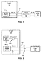
- Figure 1 shows an arrangement for energizing a load 10 which is external to a television set 12.
- the load to requires a high current, such as two amperes, which is beyond the capability of connector 14, which has an ampacity rating of one ampere.
- the invention therefore provides a twelve volt supply 18, which provides twelve volts at one ampere. This is within the ampacity rating of connector 14.
- a converter means such as buck converter 16, converts the twelve volts at one ampere to five volts at two amperes, in order to energize load 10. In this way, connector 14, which has an ampacity rating of one ampere, is able to supply load 10, which draws two amperes.
- FIG. 2 shows another embodiment of the invention.
- TV set 120 contains a five volt power supply 180 which produces one ampere through connector 140, which has an ampacity of one ampere.
- intermittent load 100 which is external of the TV set, draws more than one ampere, such as in the range of two amperes.
- the invention provides a high value capacitance 160, such as a five farad Supercap, coupled across the supply for intermittent load 100. Capacitance 160 may be charged by the current from power supply 160, which produces one ampere. However, since load 100 is intermittent, it may draw a higher value of current from capacitance 160.
- the embodiment of the invention shown in Figure 2 may be used to supply current to a continuous load, such as memory 200, through regulator 190, in the event that there is a failure of power supply 180.
Landscapes
- Engineering & Computer Science (AREA)
- Power Engineering (AREA)
- Multimedia (AREA)
- Signal Processing (AREA)
- Dc-Dc Converters (AREA)
- Television Receiver Circuits (AREA)
- Direct Current Feeding And Distribution (AREA)
- Stand-By Power Supply Arrangements (AREA)
- Circuit Arrangement For Electric Light Sources In General (AREA)
- Emergency Protection Circuit Devices (AREA)
- Charge And Discharge Circuits For Batteries Or The Like (AREA)
Abstract

Description
Claims (6)
- A power supply arrangement for passing power through a connector (14) having a limited ampacity, comprising:a load (10) having a predetermined voltage and amperage requirement;a power source (18) having a voltage higher than said load requirement and producing a current lower than said load requirement;a converter means (16) for converting said source of high voltage at low current to a lower voltage at higher current;the output of said power source (18) being coupled through said connector (14) to the input of said converter means (16); andthe output of said converter means (16) being coupled to said load (10).
- A power supply arrangement according to Claim 1, in which said source (18) produces a current within the ampacity of said connector (14), and said load (10) draws a current greater than the ampacity of said connector (14).
- A power supply arrangement for passing power through a connector (140) having a limited ampacity comprising:an intermittent load (100) having a predetermined voltage and amperage requirement;a power source (180) having a voltage approximately equal to said predetermined voltage requirement, and producing a current less than said amperage requirement;a capacitance (160);said power source (180) being coupled through said connector (140) to said capacitance (160); andsaid intermittent load (100) being coupled to said capacitance.
- A power supply arrangement according to Claim 3, in which said source (180) is coupled to a continuous load (200), said capacitance (160) powering said continuous load in the event of failure of said source (180).
- A power supply arrangement according to Claim 3, in which said power source (180) produces a value of current within the ampacity of said connector (140) and said intermittent load (100) draws a value of current greater than the ampacity of said connector (140).
- A power supply arrangement according to Claim 5, in which said intermittent load (100) draws current from both said power source (180) and said capacitance (160).
Applications Claiming Priority (2)
| Application Number | Priority Date | Filing Date | Title |
|---|---|---|---|
| US09/896,256 US6683395B2 (en) | 2001-06-29 | 2001-06-29 | Power supply |
| US896256 | 2001-06-29 |
Publications (2)
| Publication Number | Publication Date |
|---|---|
| EP1271755A2 true EP1271755A2 (en) | 2003-01-02 |
| EP1271755A3 EP1271755A3 (en) | 2003-03-19 |
Family
ID=25405894
Family Applications (1)
| Application Number | Title | Priority Date | Filing Date |
|---|---|---|---|
| EP02291461A Withdrawn EP1271755A3 (en) | 2001-06-29 | 2002-06-12 | Power supply |
Country Status (8)
| Country | Link |
|---|---|
| US (1) | US6683395B2 (en) |
| EP (1) | EP1271755A3 (en) |
| JP (1) | JP4390434B2 (en) |
| KR (1) | KR100992054B1 (en) |
| CN (1) | CN100521472C (en) |
| MX (1) | MXPA02006582A (en) |
| MY (1) | MY126194A (en) |
| TW (1) | TW565986B (en) |
Families Citing this family (5)
| Publication number | Priority date | Publication date | Assignee | Title |
|---|---|---|---|---|
| JP2003142591A (en) * | 2001-11-08 | 2003-05-16 | Denso Corp | Semiconductor integrated circuit device |
| AU2002951291A0 (en) * | 2002-09-09 | 2002-09-19 | Energy Storage Systems Pty Ltd | A power supply |
| US20140071818A1 (en) * | 2004-07-16 | 2014-03-13 | Virginia Innovation Sciences, Inc. | Method and system for efficient communication |
| CN106939995A (en) * | 2016-11-17 | 2017-07-11 | 东莞市晧业工业设计有限公司 | Photovoltaic intelligent street lamp |
| JP7218071B2 (en) | 2020-08-19 | 2023-02-06 | 矢崎総業株式会社 | power supply |
Family Cites Families (11)
| Publication number | Priority date | Publication date | Assignee | Title |
|---|---|---|---|---|
| US4464559A (en) | 1982-05-03 | 1984-08-07 | Teledyne-Walterboro, A Divison Of Teledyne Industries, Inc. | Phase-converting, variable output, power source utilizing Scott connection |
| US4716274A (en) | 1985-10-25 | 1987-12-29 | Gilliland Malcolm T | Distributed station welding system |
| US5173169A (en) | 1991-05-08 | 1992-12-22 | Aqua Dynamics Group Corp. | Electroplating method and apparatus |
| US5225971A (en) | 1992-01-08 | 1993-07-06 | International Business Machines Corporation | Three coil bridge transformer |
| KR100275621B1 (en) * | 1993-12-27 | 2001-01-15 | 박영구 | Heating device for welding stud pin of panel |
| FR2728408B1 (en) * | 1994-12-20 | 1997-01-31 | Alsthom Cge Alcatel | ELECTRICAL SUPPLY DEVICE, PARTICULARLY FOR PORTABLE DEVICES |
| US5811757A (en) | 1996-02-29 | 1998-09-22 | The Esab Group, Inc. | Power source including parallel switching circuits and related methods for a welding or cutting system |
| KR100373238B1 (en) * | 1996-08-20 | 2003-05-09 | 기아자동차주식회사 | Electric current controller |
| US5805436A (en) * | 1997-03-24 | 1998-09-08 | Lin; Tieng-Fu | Simplified power supply circuit without transformer core and windings |
| KR100327361B1 (en) * | 1999-05-06 | 2002-03-06 | 구자홍 | Power Supply |
| US6198245B1 (en) | 1999-09-20 | 2001-03-06 | O2 Micro International Ltd. | Look-ahead closed-loop thermal management |
-
2001
- 2001-06-29 US US09/896,256 patent/US6683395B2/en not_active Expired - Lifetime
-
2002
- 2002-05-31 TW TW091111700A patent/TW565986B/en not_active IP Right Cessation
- 2002-06-12 EP EP02291461A patent/EP1271755A3/en not_active Withdrawn
- 2002-06-26 KR KR1020020035848A patent/KR100992054B1/en not_active Expired - Lifetime
- 2002-06-27 JP JP2002187002A patent/JP4390434B2/en not_active Expired - Lifetime
- 2002-06-27 MY MYPI20022430A patent/MY126194A/en unknown
- 2002-06-28 CN CNB021251525A patent/CN100521472C/en not_active Expired - Lifetime
- 2002-06-28 MX MXPA02006582A patent/MXPA02006582A/en not_active Application Discontinuation
Also Published As
| Publication number | Publication date |
|---|---|
| US20030001437A1 (en) | 2003-01-02 |
| US6683395B2 (en) | 2004-01-27 |
| CN100521472C (en) | 2009-07-29 |
| MXPA02006582A (en) | 2004-08-11 |
| KR100992054B1 (en) | 2010-11-05 |
| KR20030003024A (en) | 2003-01-09 |
| CN1420612A (en) | 2003-05-28 |
| MY126194A (en) | 2006-09-29 |
| JP2003116078A (en) | 2003-04-18 |
| TW565986B (en) | 2003-12-11 |
| JP4390434B2 (en) | 2009-12-24 |
| EP1271755A3 (en) | 2003-03-19 |
Similar Documents
| Publication | Publication Date | Title |
|---|---|---|
| CN110326183B (en) | Charging device and vehicle power supply unit | |
| US10523032B2 (en) | Charging apparatus with multiple power paths | |
| US9499060B2 (en) | Power conversion device | |
| EP2393153A1 (en) | Energy storage system | |
| US8055917B2 (en) | Computer and power supply method thereof | |
| WO2003012966A8 (en) | Fuel cell inverter | |
| KR101319284B1 (en) | Dc-dc converter and power supply device | |
| US10177420B2 (en) | Charger circuit and power conversion circuit thereof | |
| US6683395B2 (en) | Power supply | |
| US7535194B2 (en) | Fuel cell system built as a system in which a fuel cell and an electric device are provided in parallel | |
| WO2000059444B1 (en) | Electrical power system for a self-contained transportable life support system | |
| CN113452097A (en) | Charging circuit, method and system, battery and electronic equipment | |
| EP2849325B1 (en) | Inverter for photovoltaic modules | |
| CN112803794A (en) | Power adapter, power supply system and power supply method | |
| CN217427697U (en) | PD charger display screen control circuit and PD charger | |
| US20050286275A1 (en) | Power supply for portable printer | |
| CN115022760B (en) | Earphone box circuit, earphone box and earphone charging system | |
| CN107979121A (en) | Charging circuit and power conversion circuit thereof | |
| CN107846143B (en) | Capacitive power conversion circuit and charging control method | |
| CN214069627U (en) | Boosting power supply based on metal-air battery and metal-air battery | |
| JP2002374677A (en) | Circuit device for obtaining DC voltage | |
| CN216312747U (en) | Receiver UPS circuit | |
| KR100428372B1 (en) | Multi-voltage output type alternator of vehicle | |
| KR0137052Y1 (en) | Back up battery of power supply | |
| CN112713661B (en) | Signal transmission system and electronic equipment for wireless reverse charging |
Legal Events
| Date | Code | Title | Description |
|---|---|---|---|
| PUAI | Public reference made under article 153(3) epc to a published international application that has entered the european phase |
Free format text: ORIGINAL CODE: 0009012 |
|
| AK | Designated contracting states |
Kind code of ref document: A2 Designated state(s): AT BE CH CY DE DK ES FI FR GB GR IE IT LI LU MC NL PT SE TR |
|
| AX | Request for extension of the european patent |
Free format text: AL;LT;LV;MK;RO;SI |
|
| PUAL | Search report despatched |
Free format text: ORIGINAL CODE: 0009013 |
|
| AK | Designated contracting states |
Kind code of ref document: A3 Designated state(s): AT BE CH CY DE DK ES FI FR GB GR IE IT LI LU MC NL PT SE TR Designated state(s): AT BE CH CY DE DK ES FI FR GB GR IE IT LI LU MC NL PT SE TR |
|
| AX | Request for extension of the european patent |
Extension state: AL LT LV MK RO SI |
|
| 17P | Request for examination filed |
Effective date: 20030816 |
|
| AKX | Designation fees paid |
Designated state(s): DE FR GB IT |
|
| RAP1 | Party data changed (applicant data changed or rights of an application transferred) |
Owner name: THOMSON LICENSING |
|
| RAP1 | Party data changed (applicant data changed or rights of an application transferred) |
Owner name: THOMSON LICENSING |
|
| 17Q | First examination report despatched |
Effective date: 20150914 |
|
| STAA | Information on the status of an ep patent application or granted ep patent |
Free format text: STATUS: THE APPLICATION IS DEEMED TO BE WITHDRAWN |
|
| 18D | Application deemed to be withdrawn |
Effective date: 20160325 |