EP1271751B1 - Electric machine having rhombus-shaped permanent magnets - Google Patents
Electric machine having rhombus-shaped permanent magnets Download PDFInfo
- Publication number
- EP1271751B1 EP1271751B1 EP02014344A EP02014344A EP1271751B1 EP 1271751 B1 EP1271751 B1 EP 1271751B1 EP 02014344 A EP02014344 A EP 02014344A EP 02014344 A EP02014344 A EP 02014344A EP 1271751 B1 EP1271751 B1 EP 1271751B1
- Authority
- EP
- European Patent Office
- Prior art keywords
- rotor
- magnet
- tapered
- circumferential
- cores
- Prior art date
- Legal status (The legal status is an assumption and is not a legal conclusion. Google has not performed a legal analysis and makes no representation as to the accuracy of the status listed.)
- Expired - Lifetime
Links
- 230000004907 flux Effects 0.000 claims description 23
- 230000002093 peripheral effect Effects 0.000 claims description 8
- 230000007423 decrease Effects 0.000 claims description 4
- 238000004804 winding Methods 0.000 description 8
- 230000000052 comparative effect Effects 0.000 description 7
- 238000004378 air conditioning Methods 0.000 description 6
- 238000012423 maintenance Methods 0.000 description 3
- 238000004519 manufacturing process Methods 0.000 description 3
- 230000004048 modification Effects 0.000 description 3
- 238000012986 modification Methods 0.000 description 3
- 230000000087 stabilizing effect Effects 0.000 description 3
- 230000008859 change Effects 0.000 description 2
- 230000009467 reduction Effects 0.000 description 2
- QNRATNLHPGXHMA-XZHTYLCXSA-N (r)-(6-ethoxyquinolin-4-yl)-[(2s,4s,5r)-5-ethyl-1-azabicyclo[2.2.2]octan-2-yl]methanol;hydrochloride Chemical compound Cl.C([C@H]([C@H](C1)CC)C2)CN1[C@@H]2[C@H](O)C1=CC=NC2=CC=C(OCC)C=C21 QNRATNLHPGXHMA-XZHTYLCXSA-N 0.000 description 1
- 230000003247 decreasing effect Effects 0.000 description 1
- 230000005347 demagnetization Effects 0.000 description 1
- 230000001419 dependent effect Effects 0.000 description 1
- 238000011161 development Methods 0.000 description 1
- 230000018109 developmental process Effects 0.000 description 1
- 239000000696 magnetic material Substances 0.000 description 1
- 239000007769 metal material Substances 0.000 description 1
Images






Classifications
-
- H—ELECTRICITY
- H02—GENERATION; CONVERSION OR DISTRIBUTION OF ELECTRIC POWER
- H02K—DYNAMO-ELECTRIC MACHINES
- H02K23/00—DC commutator motors or generators having mechanical commutator; Universal AC/DC commutator motors
- H02K23/02—DC commutator motors or generators having mechanical commutator; Universal AC/DC commutator motors characterised by arrangement for exciting
- H02K23/04—DC commutator motors or generators having mechanical commutator; Universal AC/DC commutator motors characterised by arrangement for exciting having permanent magnet excitation
-
- H—ELECTRICITY
- H02—GENERATION; CONVERSION OR DISTRIBUTION OF ELECTRIC POWER
- H02K—DYNAMO-ELECTRIC MACHINES
- H02K1/00—Details of the magnetic circuit
- H02K1/06—Details of the magnetic circuit characterised by the shape, form or construction
- H02K1/12—Stationary parts of the magnetic circuit
- H02K1/18—Means for mounting or fastening magnetic stationary parts on to, or to, the stator structures
-
- H—ELECTRICITY
- H02—GENERATION; CONVERSION OR DISTRIBUTION OF ELECTRIC POWER
- H02K—DYNAMO-ELECTRIC MACHINES
- H02K1/00—Details of the magnetic circuit
- H02K1/06—Details of the magnetic circuit characterised by the shape, form or construction
- H02K1/12—Stationary parts of the magnetic circuit
- H02K1/17—Stator cores with permanent magnets
Definitions
- a rotor 18 is rotatably received in the yoke 12.
- a drive shaft 20 extends along a rotational axis of the rotor 18 and is secured to the rotor 18 to rotate integrally with the rotor 18.
- the drive shaft 20 is rotatably supported by ball bearings 28, 29.
- a fan 15 is secured to a distal end of the drive shaft 20 to create air flow when electric current is supplied from an external power source, such as a vehicle battery, to the rotor 18 through brushes 21 and a commutator 25 to rotate the rotor 18.
- a predetermined number of cores 22 are arranged in the rotor 18 at equal angular intervals in a circumferential direction of the rotor 18.
Landscapes
- Engineering & Computer Science (AREA)
- Power Engineering (AREA)
- Permanent Field Magnets Of Synchronous Machinery (AREA)
- Permanent Magnet Type Synchronous Machine (AREA)
- Iron Core Of Rotating Electric Machines (AREA)
- Motor Or Generator Frames (AREA)
- Dc Machiner (AREA)
Description
- The present invention relates to a dynamo-electric machine, such as a blower motor of a vehicle air conditioning system.
- A motor, such as a blower motor of a vehicle air conditioning system, includes a yoke. A pair of curved magnets, which are curved to conform with an inner circumferential surface of the yoke, are secured to the inner circumferential surface of the yoke in diametrically opposed relationship to each other.
- A rotor is rotatably received within the yoke. A drive shaft extends along a rotational axis of the rotor and is secured to the rotor to rotate integrally with the rotor. A predetermined number of cores are circumferentially arranged in the rotor at equal angular intervals. Each core has a rectangular plate tooth, which radially outwardly protrudes toward the yoke. A winding is wound around each tooth.
- The blower motor of the vehicle air conditioning system is normally placed in a passenger cabin of a vehicle, so that the blower motor is required to achieve a relatively high degree of silence during rotation of the blower motor. Thus, rather than using ball bearings, which can relatively easily transmit vibrations from the rotor (armature), slide bearings made of a sintered metal material, which does not easily transmit vibrations from the rotor (armature), are commonly used to rotatably support the drive shaft of the blower motor of the vehicle air-conditioning system.
- However, the slide bearing requires oil in a contacting portion, which makes sliding contact with the drive shaft of the motor. Thus, maintenance of the oil is required, and spill of the oil from the slide bearing could occur.
- Furthermore, in the slide bearing, a washer or the like is required, causing an increase in the number of the components. This results in an increased complexity of the bearing structure of the motor and an increased complexity of the manufacturing steps of the bearing structure of the motor.
- On the other hand, unlike the slide bearing, if the ball bearing is used in the bearing structure of the motor, the oil in the contacting portion, which makes sliding contact with the drive shaft of the motor, is not required. Thus, with use of the ball bearing, the disadvantages, which result from the maintenance of the oil or the spill of the oil, can be avoided, and the washers or the like are not required. This substantially simplifies the bearing structure of the motor and the manufacturing steps of the bearing structure of the motor.
- The ball bearing can relatively easily transmit vibrations induced, particularly, by cogging torque of the rotor (i.e., torque generated in the rotor due to changes in attractive force and repulsive force between the magnets and the rotor). Thus, it is effective to reduce the cogging torque to reduce the vibrations of the rotor and to achieve a higher degree of silence during the rotation of the motor.
- One way of reducing the cogging torque is to gradually reduce a wall thickness (radial dimension) of each magnet toward its circumferential ends. However, this measure alone cannot reduce the cogging torque to an acceptable level, which allows use of the ball bearing in the blower motor of the vehicle air conditioning system.
- Another way of reducing the cogging torque is to use a rotor having skewed cores. Although this measure can reduce the cogging torque, it generally results in some disadvantages, such as a reduction in a winding surface area of each core, around which the winding is wound.
-
US 5 162 684 A suggests reducing the cogging torque by forming a field magnet from two magnetic materials having different maximum magnetic energy products -
JP 62-166757 A -
JP 04-261352 A -
JP 01-298934 A claim 1. The circumferential width of the section of the magnet opposite to the core is set to be larger than the circumferential width of the section of the core opposite to the coil end of the coil in order to prevent output performance from decreasing. - It is an objective of the present invention to provide a dynamo-electric machine, which effectively reduces cogging torque.
- To achieve the objective of the present invention, there is provided a dynamo-electric machine as defined in
claim 1. - Further developments are set forth in the dependent claims.
- The invention, together with additional objectives, features and advantages thereof, will be best understood from the following description, the appended claims and the accompanying drawings in which:
-
FIG. 1 is a cross sectional view of a motor according to an embodiment of the present invention; -
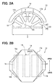
FIG. 2A is a partial plan view showing main features of the motor according to the embodiment; -
FIG. 2B is a partial side view showing a magnet of the embodiment; -
FIG. 3 is a schematic plan view showing main features of the motor according to the embodiment; -
FIG. 4 is a developed view showing a state where one of teeth is centered on a circumferential center of a range X of a magnet, which is configured to satisfy a condition of (Dπ/Z)Xn+T<X<(Dπ/Z)X(n+1)-T according to the embodiment; -
FIG. 5 is another developed view showing a state where the rotor is rotated to make π/Z rotation from the state shown inFIG. 4 ; -
FIG. 6 is a developed view showing a state where one of teeth is centered on a circumferential center of a range X of a magnet that is configured to satisfy a condition of (Dπ/Z)X(n-1)+T<X<(Dπ/Z)Xn-T according to the embodiment; -
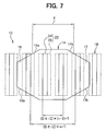
FIG. 7 is another developed view showing a state where the rotor is rotated to make π/Z rotation from the state shown inFIG. 6 ; -
FIG. 8 is a graph showing a relationship between rotated time period of the rotor and a generated cogging torque in the embodiment; -
FIG. 9 is a graph showing a relationship between a dimension of X and a generated cogging torque; -
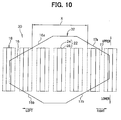
FIG. 10 is a developed view showing a modification of the magnet of the embodiment, in which the magnet is non-symmetrical with respect to its circumferential center line nor with respect to its vertical center line but is symmetrical with respect to its center point; -
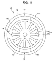
FIG. 11 is a plan view showing another modification of the magnet, in which each magnet is non-symmetrical with respect to its circumferential center line; -
FIG. 12 is a developed view showing a state where one of teeth faces a center of a range X of a magnet of a motor in a first comparative example; -
FIG. 13 is a developed view showing a state where the rotor is rotated to make π/Z rotation from the state ofFIG. 12 ; -
FIG. 14 is a developed view showing a state where one of teeth is centered on a circumferential center of a range X of a magnet of a motor in a second comparative example; -
FIG. 15 is a developed view showing a state where the rotor is rotated to make π/Z rotation from the state ofFIG. 14 ; and -
FIG. 16 is a graph showing a rotated time period of the rotor and a generated cogging torque in the first or second comparative example. - A motor (acting as a dynamo-electric machine) according to an embodiment of the present invention will be described with reference to the accompanying drawings.
- With reference to
FIGS. 1 to 7 , themotor 10 of the present embodiment is constructed as a blower motor of a vehicle air-conditioning system and has acylindrical yoke 12. Theyoke 12 is supported by amotor holder 13 and is secured to themotor holder 13 withscrews 19. - A pair of
curved magnets 14, which are curved to conform with an inner circumferential surface of theyoke 12, are secured to the inner circumferential surface of theyoke 12. Themagnets 14 are diametrically opposed to each other and have substantially the same shape. A wall thickness (radial dimension) of eachmagnet 14 is gradually reduced toward circumferential ends of themagnet 14. - As shown in
FIG. 2B , eachmagnet 14 has first and second taperedportions portion 16 has axially opposed first and second taperedplanar surfaces tapered portion 17 has axially opposed first and second taperedplanar surfaces tapered portions tapered surface tapered surface tapered portion magnet 14 is formed to be symmetrical with respect to a circumferential center line and also with respect to a vertical center line of themagnet 14. - A
rotor 18 is rotatably received in theyoke 12. Adrive shaft 20 extends along a rotational axis of therotor 18 and is secured to therotor 18 to rotate integrally with therotor 18. Thedrive shaft 20 is rotatably supported byball bearings fan 15 is secured to a distal end of thedrive shaft 20 to create air flow when electric current is supplied from an external power source, such as a vehicle battery, to therotor 18 throughbrushes 21 and acommutator 25 to rotate therotor 18. A predetermined number ofcores 22 are arranged in therotor 18 at equal angular intervals in a circumferential direction of therotor 18. With reference toFIG. 2B , a vertical length (axial dimension) of each core 22 is greater than a vertical length (axial dimension) of each circumferential end surface of eachmagnet 14, and a vertical center (axial center) of each core 22 is at the same height (the same axial position) as a vertical center of eachmagnet 14. - Each
core 22 includes arectangular plate tooth 24, which radially protrudes toward theyoke 12. A winding 27 (FIG. 1 ) is wound around eachtooth 24. It should be noted that thewindings 27 are eliminated in the drawings exceptFIG. 1 for the sake of clarity. Furthermore, anextended portion 26 is formed in a distal end of eachtooth 24. Eachextended portion 26 extends in the circumferential direction on both circumferential sides of thetooth 24 to prevent detachment of the winding from thetooth 24. - In this embodiment, the number of cores 22 (the number of slots) of the
rotor 18 is represented by Z (in this embodiment, Z is twelve). Also, as shown inFIG. 2A , an outer diameter of therotor 18 is represented by D (in this embodiment, D is 44.7 mm), and a width (circumferential dimension) of eachtooth 24 in the circumferential direction is represented by T (in this embodiment, T is 2.4 mm). With reference toFIG. 4 , the firsttapered surface 16a of the first taperedportion 16 has a first opposing point, which is radially opposed to a first imaginary end circle defined by outer peripheral surfaces of thecores 22 at one axial ends of thecores 22. InFIG. 4 , the first imaginary end circle is defined to extend along the upper ends of thecores 22. The secondtapered surface 16b of the first taperedportion 16 has a second opposing point, which is radially opposed to a second imaginary end circle defined by the outer peripheral surfaces of thecores 22 at the other axial ends of thecores 22. InFIG. 4 , the second imaginary end circle is defined to extend along the lower ends of thecores 22. Likewise, the firsttapered surface 17a of the second taperedportion 17 has a first opposing point, which is radially opposed to the first imaginary end circle defined by the outer peripheral surfaces of thecores 22 at the one axial ends of thecores 22. The secondtapered surface 17b of the second taperedportion 17 has a second opposing point, which is radially opposed to the second imaginary end circle defined by the outer peripheral surfaces of thecores 22 at the other axial ends of thecores 22. When eachmagnet 14 is viewed from a radial direction, a circumferential dimension between a circumferentially innermost one of the first and second opposing points of the first taperedportion 16 and a circumferentially innermost one of the first and second opposing points of the second taperedportion 17 is represented by X. The circumferential dimension X can be measured along an inner peripheral surface of eachmagnet 14. Alternatively, the circumferential dimension X can be measured along the outer peripheral surfaces of thecores 22 as a circumferential dimension between one point, which radially opposes the circumferentially innermost one of the first and second opposing points of the first taperedportion 16, and another point, which radially opposes the circumferentially innermost one of the first and second opposing points of the second taperedportion 17, as shown inFIG 2A . The number of theteeth 24, which are entirely placed within a range defined by X when a circumferential center of one of theteeth 24 is radially opposed to a circumferential center of the range defined by X, is represented by n (n is an odd integer, which is equal to or greater than 1 but is equal to or less than Z, and n in this embodiment is three). Therotor 18 and themagnets 14 are configured to satisfy one of the following conditions: (Dπ/Z)×n+T<X<(Dπ/Z)×(n+1)-T in the case ofFIGS. 4 and5 and (Dπ/Z)×(n-1)+T<X<(Dπ/Z)×n-T in the case ofFIGS. 6 and7 . - Operation of the present embodiment will be described.
- In each of the first and second
tapered portions magnet 14, the axial distance between the firsttapered surface tapered surface portion magnets 14 and therotor 18 does not abruptly change during the rotation of therotor 18, and thus the cogging torque generated in therotor 18 is advantageously reduced. - With reference to
FIG. 3 , in themotor 10 according to the present embodiment, the magnetic flux generated from themagnets 14 forms a magnetic circuit Y, which flows in theyoke 12 and thecores 22 of therotor 18. Thus, when thecores 22 are symmetrically arranged with respect to the center of the range X of themagnet 14, and none of theteeth 24 of thecores 22 faces the circumferential ends of the range X of themagnet 14, the magnetic flux, which flows in theteeth 24 that face the range X of themagnet 14, is stabilized. Furthermore, when therotor 18 is rotated from this stable state of the magnetic flux where the magnetic flux is stabilized, the magnetic flux changes (i.e., decreases and increases) until therotor 18 is rotated to the next stable state, causing generation of the cogging torque due to the variation of the magnetic flux. - The stable state of the magnetic flux normally occurs once per 2π/Z (i.e., one slot) rotation of the
rotor 18, and the magnetic flux varies or changes during an interval between the two successive stable states to cause generation of the cogging torque (FIG. 16 ). - With reference to
FIG. 8 , when the stable state of the magnetic flux occurs twice per 2π/Z (i.e., one slot) rotation of therotor 18, the variation of the magnetic flux between the two successive stable states is divided and is thus advantageously reduced to further reduce the cogging torque (in this case, the cogging torque is reduced to one half of the cogging torque generated in the above case where the stable state of the magnetic flux occurs once per 2π/Z rotation of the rotor 18). - With reference to
FIGS. 4 and6 , when one of theteeth 24 is centered on the circumferential center of the range X of themagnet 14, the number of theteeth 24, which are entirely placed within the range X of themagnet 14, is n, and none of theteeth 24 faces the circumferential ends of the range X of themagnet 14. This is achieved by satisfying the following condition (condition for stabilizing the magnetic flux) ofequation 1.
- Then, in the one case shown in
FIG. 5 , when therotor 18 is rotated to make π/Z (i.e., one half slot) rotation from the above state shown inFIG. 4 where the one of theteeth 24 is centered on the circumferential center of the range X of themagnet 14, the number of theteeth 24, which are entirely placed within the range X of themagnet 14, is n+1, and none of theteeth 24 faces the circumferential ends of the range X of themagnet 14. This is achieved by satisfying the following condition (condition for stabilizing the magnetic flux) of equation 2.
- Alternatively, in the other case shown in
FIG. 7 , when therotor 18 is rotated to make π/Z (i.e., one half slot) rotation from the above state shown inFIG. 6 where the one of theteeth 24 is centered on the circumferential center of the range X of themagnet 14, the number of theteeth 24, which are entirely placed in the range X of themagnet 14, is n-1, and none of theteeth 24 faces the circumferential ends of the range X of themagnet 14. This is achieved by satisfying the following condition (condition for stabilizing the magnetic flux) of equation 3.
- Thus, the
motor 10 of the present embodiment should satisfy one of the two conditions, i.e., (Dπ/Z)×n+T<X<(Dπ/Z)×(n+1)-T in the case ofFIGS. 4 and5 , which correspond to theequations 1 and 2, respectively, and (Dπ/Z)×(n-1)+T<X<(Dπ/Z)×n-T in the case ofFIGS. 6 and7 , which correspond to theequations 1 and 3, respectively. Here, (Dπ/Z)Xn+T in the condition of (Dπ/Z)×n+T<X<(Dπ/Z)×(n+1)-T represents the largest lower limit of X selected from theequations 1 and 2 (i.e., selected from (Dπ/Z)×n+T and (Dπ/Z)×n+T). Furthermore, (Dπ/Z)×(n+1)-T in the same condition of (Dπ/Z)×n+T<X<(Dπ/Z)×(n+1)-T represents the smallest upper limit of X selected from theequations 1 and 2 (i.e., selected from (Dπ/Z)×(n+1)-T and (Dπ/Z)×(n+2)-T). Also, (Dπ/Z)×(n-1)+T in the condition of (Dπ/Z)×(n-1)+T<X<(Dπ/Z)×n-T represents the largest lower limit of X selected from theequations 1 and 3 (i.e., selected from (Dπ/Z)×(n-1)+T and (Dπ/Z)×(n-2)+T). Furthermore, (Dπ/Z)×n-T in the same condition of (Dπ/Z)×(n-1)+T<X<(Dπ/Z)×n-T represents the smallest upper limit of X selected from theequations 1 and 3 (i.e., selected from (Dπ/Z)×(n+1)-T and (Dπ/Z)×n-T). With the above arrangements, the stable states of the magnetic flux can be achieved twice per 2π/Z rotation of the rotor 18 (i.e., per one slot). Thus, as shown inFIG. 9 , the cogging torque can be advantageously reduced without causing an undesirable result, such as a reduction in a winding area of the winding in each core, which occurs in the case where the skewed cores are used. - As a result, vibrations of the
rotor 18 are advantageously reduced to achieve a relatively high degree of silence during the rotation of themotor 10. Therefore, theball bearing motor 10 even in the environment where a relatively high degree of silence is required during the rotation of themotor 10. - Furthermore, unlike the case where the slide bearing is used in each baring structure of the
motor 10, when the ball bearing is used in the bearing structure of themotor 10, the oil is not required in the contacting portion of the bearing structure, which contacts thedrive shaft 20. As a result, disadvantages, which result from the maintenance of the oil and the spill of the oil, can be avoided. Furthermore, the washers or the like are not required. Thus, the bearing structure of themotor 10 and the manufacturing steps of the bearing structure of themotor 10 are substantially simplified. - Also, in the
motor 10 of the present embodiment, the wall thickness of eachmagnet 14 is gradually reduced toward the circumferential ends of themagnet 14. Thus, the attractive force or the repulsive force between themagnets 14 and therotor 18 does not abruptly change, so that the cogging torque generated in therotor 18 is advantageously reduced. - If each
magnet 14 achieves a high performance (i.e., generating relatively high magnetic force), and thus a size of themagnet 14 can be reduced, it is advantageous to satisfies the condition of (Dπ/Z)×(n-1)+T<X<(Dπ/Z)×n-T, as in the case ofFIGS. 6 and7 where the size of eachmagnet 14 is smaller than that of eachmagnet 14 shown inFIGS. 4 and5 . - Furthermore, in the present embodiment, each
magnet 14 is symmetrical with respect to its circumferential center line and also with respect to its vertical center line. However, each magnet can be modified to amagnet 32 of a motor 30 (dynamo-electric machine) shown inFIG. 10 . Themagnet 32 is non-symmetrical with respect to its circumferential center line nor with respect to a vertical center line but is symmetrical with respect to its center point. Alternatively, each magnet can be modified to amagnet 42 of a motor 40 (dynamo-electric machine) shown inFIG. 11 . Themagnet 42 is non-symmetrical with respect to its circumferential center line. In themotor 30 shown inFIG. 10 , X is the circumferential dimension between the first opposing point of the firsttapered surface 16a of the first taperedportion 16 and the second opposing point of the secondtapered surface 17b of the second taperedportion 17. - Furthermore, in the present embodiment, the pair of diametrically
opposed magnets 14 are provided. The present invention is not limited to this arrangement, and the number of themagnets 14 can be changed to any even number. - Also, in the present embodiment, each
tapered surface tapered surface - In the above embodiment, the wall thickness (radial dimension) of each
magnet 14 is gradually reduced toward the circumferential ends of themagnet 14. Alternatively, the wall thickness of eachmagnet 14 can be substantially uniform throughout themagnet 14. - In the above embodiment, the
ball bearings drive shaft 20. Alternatively, at least one of theball bearings drive shaft 20. - Two comparative examples will be described with reference to
FIGS. 12 to 16 to illustrate the advantages of the above embodiment. In these comparative examples, components similar to those discussed in the above embodiment will be indicated with similar numerals and will not be discussed further. - In a motor 50 (dynamo-electric machine) of the first comparative example shown in
FIGS. 12 and13 , when one ofteeth 24 is centered on a circumferential center of a range X of amagnet 52, twoteeth 24 face circumferential ends of the range X of themagnet 52, respectively, resulting in an unstable state of magnetic flux (FIG. 12 ). At this state, when therotor 18 is rotated to make π/Z (i.e., one half slot) rotation, none of theteeth 24 faces the circumferential ends of the range X of themagnet 52, resulting in a stable state of the magnetic flux (FIG 13 ). - Furthermore, in a motor 60 (dynamo-electric machine) of the second comparative example shown in
FIGS. 14 and15 , when one ofteeth 24 is centered on a circumferential center of a range X of amagnet 62, none of theteeth 24 faces the circumferential ends of the range X of themagnet 62, resulting in a stable state of magnetic flux (FIG 14 ). At this state, when therotor 18 is rotated to make π/Z (i.e., one half slot) rotation, twoteeth 24 face circumferential ends of the range X of themagnet 62, respectively, resulting in an unstable state of magnetic flux (FIG. 15 ). - Thus, as shown in
FIG. 16 , in thesemotors rotor 18. As a result, the magnetic flux largely changes between the two successive stable states of the magnetic flux, resulting in generation of a relatively large cogging torque. - Additional advantages and modifications will readily occur to those skilled in the art. The invention in its broader terms is therefore, not limited to the specific details, representative apparatus, and illustrative examples shown and described.
Claims (4)
- A dynamo-electric machine including:a yoke (12);a rotor (18), which is rotatably received in the yoke (12) and includes a predetermined number of cores (22) circumferentially arranged at substantially equal angular intervals, wherein each core (22) includes a tooth (24), which radially outwardly extends toward the yoke (12); anda plurality of curved magnets (14), which are secured to an inner circumferential surface of the yoke (12),wherein each magnet (14) has first and second tapered portions (16, 17), which are tapered in opposite circumferential directions, wherein each of the first and second tapered portions (16, 17) has axially opposed first and second tapered surfaces (16a, 16b; 17a, 17b), and an axial distance between the first tapered surface (16a, 17a) and the second tapered surface (17a, 17b) of each of the first and second tapered portions (16, 17) decreases toward an outer circumferential end of each of the first and second tapered portions (16, 17),characterized in thatthe first tapered surface (16a, 17a) of each of the first and second tapered portions (16, 17) has a first opposing point, which is radially opposed to a first imaginary end circle defined by outer peripheral surfaces of the cores (22) at one axial ends of the cores (22), and the second tapered surface (16b, 17b) of each of the first and second tapered portions (16, 17) has a second opposing point, which is radially opposed to a second imaginary end circle defined by the outer peripheral surfaces of the cores (22) at the other axial ends of the cores (22);the rotor (18) and each magnet (14) are configured to satisfy one of the following conditions:

and
whereinZ is a number of the cores (22) of the rotor (18), D is an outer diameter of the rotor (18), T is a circumferential dimension of each tooth (24), X is a circumferential dimension between a circumferentially innermost one of the first and second opposing points of the first tapered portion (16) and a circumferentially innermost one of the first and second opposing points of the second tapered portion (17) when each magnet (14) is viewed from a radial direction, and n is an odd integer defining the number of the teeth (24) that are entirely placed within a range defined by X when a circumferential center of one of the teeth (24) is radially opposed to a circumferential center of the range defined by X; anda stable state of magnetic flux generated from the magnets (14) occurs twice per 2π/Z rotation of the rotor (18). - A dynamo-electric machine according to claim 1, further comprising:a drive shaft (20), which extends along a rotational axis of the rotor (18) and is secured to the rotor (18) to rotate integrally with the rotor (18); andat least one ball bearing, which rotatably supports the drive shaft (20).
- A dynamo-electric machine according to claim 1 or 2, wherein each tooth (24) axially extends along a line parallel to an axial direction of the rotor (18).
- A dynamo-electric machine according to any one of claims 1 to 3, wherein a radial dimension of each magnet (14) is substantially uniform throughout each magnet (14).
Applications Claiming Priority (2)
| Application Number | Priority Date | Filing Date | Title |
|---|---|---|---|
| JP2001199999A JP4740480B2 (en) | 2001-06-29 | 2001-06-29 | Rotating electric machine |
| JP2001199999 | 2001-06-29 |
Publications (2)
| Publication Number | Publication Date |
|---|---|
| EP1271751A1 EP1271751A1 (en) | 2003-01-02 |
| EP1271751B1 true EP1271751B1 (en) | 2012-12-19 |
Family
ID=19037199
Family Applications (1)
| Application Number | Title | Priority Date | Filing Date |
|---|---|---|---|
| EP02014344A Expired - Lifetime EP1271751B1 (en) | 2001-06-29 | 2002-06-27 | Electric machine having rhombus-shaped permanent magnets |
Country Status (5)
| Country | Link |
|---|---|
| US (1) | US6710493B2 (en) |
| EP (1) | EP1271751B1 (en) |
| JP (1) | JP4740480B2 (en) |
| KR (1) | KR100554599B1 (en) |
| CN (1) | CN1393972B (en) |
Families Citing this family (12)
| Publication number | Priority date | Publication date | Assignee | Title |
|---|---|---|---|---|
| JP3887342B2 (en) * | 2003-04-03 | 2007-02-28 | ミネベア株式会社 | Proportional rotary torquer |
| KR101033572B1 (en) * | 2004-02-26 | 2011-05-11 | 엘지전자 주식회사 | Stator structure of outer rotor type motor for drum washing machine |
| US7687953B2 (en) * | 2005-04-21 | 2010-03-30 | Brose Fahrzeugteile GmbH & Co. Kommanditgesellschaft, Würzburg | Totally integrated engine cooling module for D.C. motors employing fan hub and shroud hub as motor covers |
| US8706768B2 (en) * | 2008-05-16 | 2014-04-22 | Ricoh Company, Ltd. | Managing to-do lists in task schedules in a project management system |
| KR100957099B1 (en) * | 2008-05-26 | 2010-05-13 | 현대자동차주식회사 | Automotive blower motor with vibration absorbing bearing and vibration absorbing bearing |
| US8278774B2 (en) * | 2009-06-29 | 2012-10-02 | Pratt & Whitney Canada Corp. | Gas turbine with wired shaft forming part of a generator/motor assembly |
| US8097972B2 (en) * | 2009-06-29 | 2012-01-17 | Pratt & Whitney Canada Corp. | Gas turbine with magnetic shaft forming part of a generator/motor assembly |
| CN102255409A (en) * | 2010-05-18 | 2011-11-23 | 佶庆电机有限公司 | Motor device |
| CN105447049B (en) * | 2014-09-02 | 2021-08-10 | 中国移动通信集团公司 | Message display method and device and terminal |
| CN107437880A (en) * | 2016-05-26 | 2017-12-05 | 德昌电机(深圳)有限公司 | Magneto and the household electrical appliance with the motor |
| CN115800567B (en) * | 2022-11-23 | 2025-11-11 | 浙江联宜电机有限公司 | Magnetic steel structure of direct current brush motor and direct current brush motor |
| CN118739659B (en) * | 2023-03-31 | 2025-10-31 | 比亚迪股份有限公司 | Rotor assembly, motor and vehicle |
Family Cites Families (25)
| Publication number | Priority date | Publication date | Assignee | Title |
|---|---|---|---|---|
| US4341969A (en) * | 1980-12-01 | 1982-07-27 | Honeywell Inc. | Direct current motor with improved pole piece that reduces cogging |
| JPH0744809B2 (en) | 1985-03-29 | 1995-05-15 | 株式会社日立製作所 | Field device for small electric motors |
| JPS6248246A (en) | 1985-08-27 | 1987-03-02 | Moriyama Kogyo Kk | Rotary machine of permanent magnet |
| JPS62166757A (en) | 1986-01-20 | 1987-07-23 | Matsushita Electric Ind Co Ltd | Field magnet |
| JPH07118876B2 (en) * | 1986-03-24 | 1995-12-18 | 三菱電機株式会社 | Method for manufacturing yoke of magnet type electric motor |
| JPS63277450A (en) * | 1987-05-06 | 1988-11-15 | Fanuc Ltd | Permanent magnet for three-phase a.c. synchronous motor |
| JP2609286B2 (en) | 1988-05-27 | 1997-05-14 | 株式会社日立製作所 | Permanent magnet rotating machine |
| JPH0374164A (en) * | 1989-08-14 | 1991-03-28 | Hitachi Ltd | Motor |
| JPH069578Y2 (en) * | 1989-08-29 | 1994-03-09 | マブチモーター株式会社 | Field magnet for small motors |
| US5206556A (en) * | 1989-08-29 | 1993-04-27 | Mabuchi Motor Co., Ltd. | Field magnet for miniature motors |
| US5237231A (en) * | 1989-10-19 | 1993-08-17 | General Electric Company | Structured product dynamoelectric machine |
| JPH0426338A (en) * | 1990-05-17 | 1992-01-29 | Fanuc Ltd | Rotor structure of synchronous motor |
| JP2888653B2 (en) * | 1991-02-15 | 1999-05-10 | アスモ株式会社 | DC motor |
| JP2536882Y2 (en) | 1991-07-08 | 1997-05-28 | アスモ株式会社 | Rotating electric machine |
| JPH05111204A (en) | 1991-10-09 | 1993-04-30 | Toshiba Corp | Inner rotor type motor |
| JPH07203665A (en) | 1993-12-28 | 1995-08-04 | Asmo Co Ltd | Electric rotating machine |
| US5660786A (en) | 1994-06-29 | 1997-08-26 | U.S. Philips Corporation | Method of manufacturing ferrite magnets for motors |
| JPH09163646A (en) | 1995-11-30 | 1997-06-20 | Matsushita Electric Ind Co Ltd | motor |
| JPH09182326A (en) | 1995-12-21 | 1997-07-11 | Jeco Co Ltd | Dc motor |
| JP3610667B2 (en) | 1996-04-09 | 2005-01-19 | 松下電器産業株式会社 | motor |
| JPH10108430A (en) | 1996-09-27 | 1998-04-24 | Matsushita Electric Ind Co Ltd | motor |
| JPH1118390A (en) | 1997-06-20 | 1999-01-22 | Mabuchi Motor Co Ltd | Small motor |
| JPH1198799A (en) | 1997-09-18 | 1999-04-09 | Matsushita Electric Ind Co Ltd | DC motor |
| JPH11178301A (en) | 1997-12-15 | 1999-07-02 | Matsushita Electric Works Ltd | Motor |
| JP2002247827A (en) * | 2001-02-20 | 2002-08-30 | Moric Co Ltd | Dc motor |
-
2001
- 2001-06-29 JP JP2001199999A patent/JP4740480B2/en not_active Expired - Fee Related
-
2002
- 2002-05-28 US US10/155,019 patent/US6710493B2/en not_active Expired - Lifetime
- 2002-06-20 CN CN021226989A patent/CN1393972B/en not_active Expired - Lifetime
- 2002-06-27 KR KR1020020036366A patent/KR100554599B1/en not_active Expired - Fee Related
- 2002-06-27 EP EP02014344A patent/EP1271751B1/en not_active Expired - Lifetime
Also Published As
| Publication number | Publication date |
|---|---|
| CN1393972B (en) | 2010-04-28 |
| US6710493B2 (en) | 2004-03-23 |
| CN1393972A (en) | 2003-01-29 |
| KR100554599B1 (en) | 2006-03-03 |
| EP1271751A1 (en) | 2003-01-02 |
| US20030001449A1 (en) | 2003-01-02 |
| JP2003018812A (en) | 2003-01-17 |
| KR20030003048A (en) | 2003-01-09 |
| JP4740480B2 (en) | 2011-08-03 |
Similar Documents
| Publication | Publication Date | Title |
|---|---|---|
| US6313558B1 (en) | Electric rotary machine having concentrated winding stator | |
| US7595575B2 (en) | Motor/generator to reduce cogging torque | |
| EP1414130B1 (en) | Electric motor with a permanent magnet rotor | |
| US9716411B2 (en) | Permanent-magnet-type rotating electric mechanism | |
| US5917263A (en) | Switched reluctance motor | |
| JP3607697B2 (en) | Electric motor | |
| GB2308017A (en) | Interdigitated rotor poles having interposed permanent magnets | |
| JP2007228750A (en) | Small motor with polygonal outline | |
| US6710493B2 (en) | Dynamo-electric machine having tapered magnets secured to yoke | |
| JP3675772B2 (en) | Stepping motor | |
| EP1612912A1 (en) | Permanent magnet electric machine | |
| EP1303030A2 (en) | Permanent magnet stepping motor | |
| US6958556B2 (en) | Structure of rotors in stepping motors | |
| JP4212982B2 (en) | Rotating electric machine | |
| US8288900B2 (en) | Stepping motor | |
| US20220052566A1 (en) | Stator and motor assembly including same | |
| JP4525026B2 (en) | Rotating electric machine | |
| JP2001016820A (en) | Mounting structure of rotating shaft of rotating electrical machine | |
| JP7800513B2 (en) | rotating electrical machines | |
| JP2003009499A (en) | Motor structure of claw pole type stepping motor | |
| WO2021229954A1 (en) | Rotor and electric motor | |
| KR100515989B1 (en) | Permanent magnet yoke of rotor for motor and generator | |
| KR20140118806A (en) | Thin motor | |
| JP2020129890A (en) | Rotating electric machine and hoisting system for elevator | |
| JP2001078412A (en) | Spindle motor |
Legal Events
| Date | Code | Title | Description |
|---|---|---|---|
| PUAI | Public reference made under article 153(3) epc to a published international application that has entered the european phase |
Free format text: ORIGINAL CODE: 0009012 |
|
| AK | Designated contracting states |
Kind code of ref document: A1 Designated state(s): AT BE CH CY DE DK ES FI FR GB GR IE IT LI LU MC NL PT SE TR |
|
| AX | Request for extension of the european patent |
Free format text: AL;LT;LV;MK;RO;SI |
|
| 17P | Request for examination filed |
Effective date: 20021113 |
|
| AKX | Designation fees paid |
Designated state(s): DE FR IT |
|
| 17Q | First examination report despatched |
Effective date: 20110920 |
|
| GRAP | Despatch of communication of intention to grant a patent |
Free format text: ORIGINAL CODE: EPIDOSNIGR1 |
|
| RIN1 | Information on inventor provided before grant (corrected) |
Inventor name: ITO, TOSHIMOTO Inventor name: SUZUKI, AKIHIKO Inventor name: NODA, TAKEO Inventor name: UEDA, YASUSHI Inventor name: YOSHIKAWA, SHOUICHI |
|
| GRAS | Grant fee paid |
Free format text: ORIGINAL CODE: EPIDOSNIGR3 |
|
| GRAA | (expected) grant |
Free format text: ORIGINAL CODE: 0009210 |
|
| AK | Designated contracting states |
Kind code of ref document: B1 Designated state(s): DE FR IT |
|
| REG | Reference to a national code |
Ref country code: DE Ref legal event code: R096 Ref document number: 60244236 Country of ref document: DE Effective date: 20130214 |
|
| PGFP | Annual fee paid to national office [announced via postgrant information from national office to epo] |
Ref country code: DE Payment date: 20130619 Year of fee payment: 12 |
|
| PGFP | Annual fee paid to national office [announced via postgrant information from national office to epo] |
Ref country code: IT Payment date: 20130620 Year of fee payment: 12 Ref country code: FR Payment date: 20130624 Year of fee payment: 12 |
|
| PLBE | No opposition filed within time limit |
Free format text: ORIGINAL CODE: 0009261 |
|
| STAA | Information on the status of an ep patent application or granted ep patent |
Free format text: STATUS: NO OPPOSITION FILED WITHIN TIME LIMIT |
|
| 26N | No opposition filed |
Effective date: 20130920 |
|
| REG | Reference to a national code |
Ref country code: DE Ref legal event code: R097 Ref document number: 60244236 Country of ref document: DE Effective date: 20130920 |
|
| REG | Reference to a national code |
Ref country code: DE Ref legal event code: R119 Ref document number: 60244236 Country of ref document: DE |
|
| REG | Reference to a national code |
Ref country code: FR Ref legal event code: ST Effective date: 20150227 |
|
| PG25 | Lapsed in a contracting state [announced via postgrant information from national office to epo] |
Ref country code: IT Free format text: LAPSE BECAUSE OF NON-PAYMENT OF DUE FEES Effective date: 20140627 Ref country code: DE Free format text: LAPSE BECAUSE OF NON-PAYMENT OF DUE FEES Effective date: 20150101 |
|
| REG | Reference to a national code |
Ref country code: DE Ref legal event code: R119 Ref document number: 60244236 Country of ref document: DE Effective date: 20150101 |
|
| PG25 | Lapsed in a contracting state [announced via postgrant information from national office to epo] |
Ref country code: FR Free format text: LAPSE BECAUSE OF NON-PAYMENT OF DUE FEES Effective date: 20140630 |