EP1271582A1 - Metal foil excellent in electrical contact stability - Google Patents
Metal foil excellent in electrical contact stability Download PDFInfo
- Publication number
- EP1271582A1 EP1271582A1 EP01915750A EP01915750A EP1271582A1 EP 1271582 A1 EP1271582 A1 EP 1271582A1 EP 01915750 A EP01915750 A EP 01915750A EP 01915750 A EP01915750 A EP 01915750A EP 1271582 A1 EP1271582 A1 EP 1271582A1
- Authority
- EP
- European Patent Office
- Prior art keywords
- electrical contact
- metal foil
- contact stability
- roughness
- metal
- Prior art date
- Legal status (The legal status is an assumption and is not a legal conclusion. Google has not performed a legal analysis and makes no representation as to the accuracy of the status listed.)
- Granted
Links
Classifications
-
- H—ELECTRICITY
- H01—ELECTRIC ELEMENTS
- H01H—ELECTRIC SWITCHES; RELAYS; SELECTORS; EMERGENCY PROTECTIVE DEVICES
- H01H1/00—Contacts
- H01H1/06—Contacts characterised by the shape or structure of the contact-making surface, e.g. grooved
-
- Y—GENERAL TAGGING OF NEW TECHNOLOGICAL DEVELOPMENTS; GENERAL TAGGING OF CROSS-SECTIONAL TECHNOLOGIES SPANNING OVER SEVERAL SECTIONS OF THE IPC; TECHNICAL SUBJECTS COVERED BY FORMER USPC CROSS-REFERENCE ART COLLECTIONS [XRACs] AND DIGESTS
- Y10—TECHNICAL SUBJECTS COVERED BY FORMER USPC
- Y10T—TECHNICAL SUBJECTS COVERED BY FORMER US CLASSIFICATION
- Y10T428/00—Stock material or miscellaneous articles
- Y10T428/12—All metal or with adjacent metals
- Y10T428/12431—Foil or filament smaller than 6 mils
-
- Y—GENERAL TAGGING OF NEW TECHNOLOGICAL DEVELOPMENTS; GENERAL TAGGING OF CROSS-SECTIONAL TECHNOLOGIES SPANNING OVER SEVERAL SECTIONS OF THE IPC; TECHNICAL SUBJECTS COVERED BY FORMER USPC CROSS-REFERENCE ART COLLECTIONS [XRACs] AND DIGESTS
- Y10—TECHNICAL SUBJECTS COVERED BY FORMER USPC
- Y10T—TECHNICAL SUBJECTS COVERED BY FORMER US CLASSIFICATION
- Y10T428/00—Stock material or miscellaneous articles
- Y10T428/12—All metal or with adjacent metals
- Y10T428/12493—Composite; i.e., plural, adjacent, spatially distinct metal components [e.g., layers, joint, etc.]
- Y10T428/12771—Transition metal-base component
- Y10T428/12861—Group VIII or IB metal-base component
- Y10T428/12903—Cu-base component
-
- Y—GENERAL TAGGING OF NEW TECHNOLOGICAL DEVELOPMENTS; GENERAL TAGGING OF CROSS-SECTIONAL TECHNOLOGIES SPANNING OVER SEVERAL SECTIONS OF THE IPC; TECHNICAL SUBJECTS COVERED BY FORMER USPC CROSS-REFERENCE ART COLLECTIONS [XRACs] AND DIGESTS
- Y10—TECHNICAL SUBJECTS COVERED BY FORMER USPC
- Y10T—TECHNICAL SUBJECTS COVERED BY FORMER US CLASSIFICATION
- Y10T428/00—Stock material or miscellaneous articles
- Y10T428/12—All metal or with adjacent metals
- Y10T428/12493—Composite; i.e., plural, adjacent, spatially distinct metal components [e.g., layers, joint, etc.]
- Y10T428/12771—Transition metal-base component
- Y10T428/12861—Group VIII or IB metal-base component
- Y10T428/12951—Fe-base component
- Y10T428/12972—Containing 0.01-1.7% carbon [i.e., steel]
- Y10T428/12979—Containing more than 10% nonferrous elements [e.g., high alloy, stainless]
-
- Y—GENERAL TAGGING OF NEW TECHNOLOGICAL DEVELOPMENTS; GENERAL TAGGING OF CROSS-SECTIONAL TECHNOLOGIES SPANNING OVER SEVERAL SECTIONS OF THE IPC; TECHNICAL SUBJECTS COVERED BY FORMER USPC CROSS-REFERENCE ART COLLECTIONS [XRACs] AND DIGESTS
- Y10—TECHNICAL SUBJECTS COVERED BY FORMER USPC
- Y10T—TECHNICAL SUBJECTS COVERED BY FORMER US CLASSIFICATION
- Y10T428/00—Stock material or miscellaneous articles
- Y10T428/12—All metal or with adjacent metals
- Y10T428/12993—Surface feature [e.g., rough, mirror]
Definitions
- the present invention relates to a metal foil excellent in electrical contact stability, used as the material of a metal disc spring for a keypad, a tactile switch, etc. of an electronic device, in a cable terminal board of an electric signal transmission system or the like.
- Keypads for cellular phones and tactile switches for various kinds of electronic devices wherein miniaturization and weight reduction are advancing to the extreme, must provide a feeling of a sharp click when they are pushed. Therefore, for keypads and tact switches, thin and electrically conductive metal disc springs, which have the function of switching a circuit by making them directly contact with or detach from a metal pattern formed on a printed circuit board or a switch substrate, are used.
- the main function of keypads and tactile switches used for cellular phones and various kinds of electronic devices is to transmit signals to microprocessors, digital circuits or the like contained in the devices.
- a circuit is closed by pushing a switch having poor electrical contact stability, a voltage fluctuation beyond the threshold values of an Hi potential and an Lo potential occurs owing to the fluctuation of resistance or the like at the contact portion, and this leads to an incorrect recognition as to how many times the switch has been pushed.
- Screw type cable terminal boards have so far been widely used for electric signal transmission systems but, for the ease of cable connection, pressure contact type terminal boards using a springy metal ribbon are being used. When the electrical contact stability of this kind of terminal is hindered, noise is generated, leading to various kinds of malfunctions.
- Phosphor bronze or SUS 301 stainless steel which are highly springy, have conventionally been used as the materials of a metal spring for an electrical contact.
- the problem here is that, when a disc spring formed of a foil produced from such a metal is used in a switch, sufficient electrical contact stability is not secured. Therefore, a foil produced from such a metal has been used after being plated with a metal such as gold, silver and nickel.
- the method is specifically as follows. Firstly, for the purpose of improving the adhesiveness of the subsequent Cu plating, a Ni plating layer 0.05 to 0.5 ⁇ m in thickness is formed on the surface of a stainless steel substrate, by electrolysis, using an electrolyte containing NiCl 2 and free HCl and using the stainless steel substrate as the cathode. Secondly, for the purpose of obtaining electrical conductivity, a Cu plating layer 2 to 50 ⁇ m in thickness is formed thereon, by electrolysis, using an electrolyte containing CuSO 4 and free H 2 SO 4 . Thirdly, for the purpose of protecting the Cu layer, a Ni plating layer 0.1 to 5 ⁇ m in thickness is formed thereon, by electrolysis, using an electrolyte containing NiSO 4 and NiCl 2 .
- an Au alloy plating layer 0.05 to 1 ⁇ m in thickness is formed, by electrolysis, using an electrolyte containing KAu(CN) 2 and salt of metals, except Au, such as Ni and Co with sulfamic acid.
- the object of the present invention is to provide a metal foil excellent in electrical contact stability, which does not require plating and is capable of reducing cost by eliminating plating processes.
- Phosphor bronze or stainless steel is used as a springy metal for the switches but an oxide film forms naturally on the surface of the metal when the metal is exposed to the atmosphere and, as a result, contact resistance is generated.
- electrical contact has so far been established by pressing a smooth metal surface to a counterpart metal surface, the density of contact points per unit area has been low, the state of the contacts with an oxide film between has been disturbed by slight vibrations and so on, and, as a result, a large and rapid fluctuation of the contact resistance has been generated and the electrical contact stability has been hindered.
- the gist of the present invention for solving the above problem is as follows:
- a metal foil 0.3 mm or less in thickness which is cold tempered to provide springiness is generally used as a material for electrical contacts.
- a keypad or a tactile switch is constructed by cutting out components into a disc shape from the metal foil material, forming them into a concave shape like a dish, then placing them on circuit patterns of a copper foil printed on a substrate plated with gold, silver and/or nickel, so that a circuit is closed when each of the disc-shaped components is pressed, and thereafter, mounting resin covers, rubber parts and casing components thereon for the purpose of insulating operator's fingers from the electrically conductive portions and making the touch feel smooth.
- the connecting method is changing from the conventional screw type to a press-in, ribbon-shaped spring type, considering the convenience of connecting work.
- electrical contact stability is one of the essential factors for suppressing noise generation from a contact portion and correctly transmitting electric signals to other components.
- the present inventors established, as a method of evaluating such technical conditions, a method for measuring the voltage fluctuation of a contact between a spherical electrical contact element, which was prepared by machining a tip of a copper rod 3 mm in diameter into a spherical shape and plating it with Ni in a strike plating bath and then with gold, and a metal foil, while the copper contact element was pressed onto the foil under a load of 5 g.
- an electrical circuit is formed using a dry cell as a power source and the metal foil as the ground and arranging a voltage control circuit and a resistance so that the potential of the spherical electrical contact element is 1.8 V when it does not contact with the foil.
- the potential of the spherical electrical contact element does not fluctuate, staying virtually at 0 V, but, if its electrical contact stability is poor, the reading of the potential changes from time to time, and spike-like voltage changes or the like may occur caused by the slight vibrations or the like from outside.
- the latter situation may make a signal meant to be one Lo potential signal transmitted to an electronic circuit appear to be multiple signals, and, in case of an audio circuit or a transmission circuit, it may generate noise and cause troubles.
- the test method is applied under the condition of a light pressing force, which condition is severer than the condition of a contact employed in an actual electronic device.
- the present inventors judged that the condition is appropriate for evaluating the reliability of a metal foil capable of realizing good electrical contact stability without plating, which metal foil is prepared by controlling the surface shape.
- a metal foil showing a potential fluctuation of 50 mV or less when a contact is closed is classified as good (marked with ⁇ ), and that showing a potential fluctuation exceeding 50 mV as poor ( ⁇ ).
- ⁇ the ratio of an arithmetic average of roughness Ra to an average interval Sm of the concavities and convexities
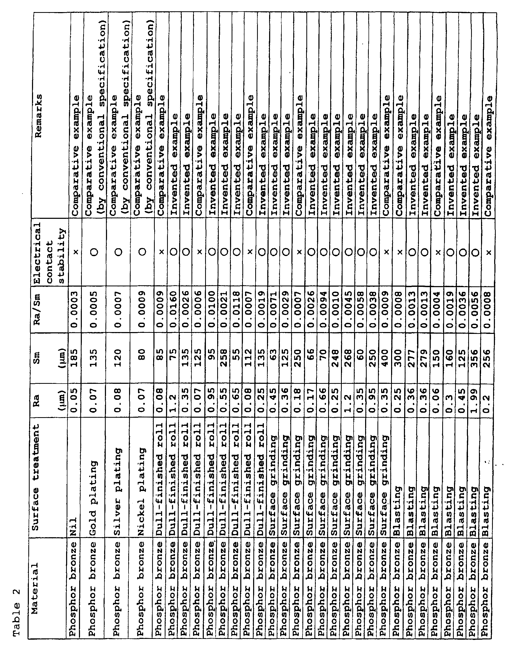
- Table 1 shows the evaluation results of the metal foils produced by using stainless steel as the base material, and Table 2 those of the metal foils produced by using phosphor bronze as the base material.
- the arithmetic average of roughness Ra specified in JIS B 0601-1994, the average interval Sm of the concavities and convexities and the ratio Ra/Sm between them are listed as the results of measuring the surface roughness of each material.
- the surface roughness was measured by using a contact type surface roughness measurement apparatus (SURFCOM 1400A-3D manufactured by Tokyo Seimitsu Co., Ltd.) and provided the data of concavities and convexities along a length of 4 mm by scanning the surface with a contact probe in the direction in which the average interval Sm of the concavities and convexities was smallest. Based on the measurement results, the above evaluation was carried out.
- a contact type surface roughness measurement apparatus (SURFCOM 1400A-3D manufactured by Tokyo Seimitsu Co., Ltd.)
- the surface unevenness was given to a material by a rolling work with dull-finished rolls, embossed rolls or the like, a grinding work with an abrasive, a coil-grinding work with silicon carbide paper, or a surface sweeping work by blasting. Any one of these methods is suitable for mass production and cost reduction.
- the arithmetic average of roughness Ra is a value corresponding to the height of the unevenness of a surface based on the definition
- the average interval Sm of concavities and convexities is interpreted as a value corresponding to the periodicity of the unevenness.
- the present invention makes it possible to improve the electrical contact stability of switch elements and terminals for electronic device products, wherein technological development in weight reduction and miniaturization is advancing, without applying plating processes, and to provide a metal foil excellent in electrical contact stability. Therefore, the present invention contributes to the cost reduction of electronic devices and, as such, it is extremely valuable industrially.
Landscapes
- Electroplating Methods And Accessories (AREA)
- Contacts (AREA)
- Manufacture Of Switches (AREA)
Abstract
Description

Claims (2)
- A metal foil excellent in electrical contact stability characterized by having a surface roughness wherein the ratio Ra/Sm between the arithmetic average of roughness Ra and the average interval Sm of concavities and convexities is 0.001 or more, which average values are obtained by measuring the roughness in the direction in which the average interval Sm of the concavities and convexities on the surface is smallest.
- A metal foil excellent in electrical contact stability according to claim 1, characterized in that the material of the metal foil is stainless steel or phosphor bronze.
Applications Claiming Priority (3)
| Application Number | Priority Date | Filing Date | Title |
|---|---|---|---|
| JP2000081315A JP4233726B2 (en) | 2000-03-23 | 2000-03-23 | Metal foil with excellent electrical contact stability |
| JP2000081315 | 2000-03-23 | ||
| PCT/JP2001/002372 WO2001071740A1 (en) | 2000-03-23 | 2001-03-23 | Metal foil excellent in electrical contact stability |
Publications (3)
| Publication Number | Publication Date |
|---|---|
| EP1271582A1 true EP1271582A1 (en) | 2003-01-02 |
| EP1271582A4 EP1271582A4 (en) | 2006-03-22 |
| EP1271582B1 EP1271582B1 (en) | 2007-09-12 |
Family
ID=18598271
Family Applications (1)
| Application Number | Title | Priority Date | Filing Date |
|---|---|---|---|
| EP01915750A Expired - Lifetime EP1271582B1 (en) | 2000-03-23 | 2001-03-23 | Metal foil excellent in electrical contact stability |
Country Status (8)
| Country | Link |
|---|---|
| US (1) | US6703143B2 (en) |
| EP (1) | EP1271582B1 (en) |
| JP (1) | JP4233726B2 (en) |
| KR (1) | KR100526451B1 (en) |
| CN (1) | CN1301520C (en) |
| DE (1) | DE60130443T2 (en) |
| TW (1) | TW491905B (en) |
| WO (1) | WO2001071740A1 (en) |
Families Citing this family (1)
| Publication number | Priority date | Publication date | Assignee | Title |
|---|---|---|---|---|
| JP2021123787A (en) * | 2020-02-07 | 2021-08-30 | 株式会社原田伸銅所 | Phosphor bronze alloy with antibacterial surface roughened with dull roll to reduce gloss (low gloss or matte) and marked amplification of antibacterial properties and articles using it |
Family Cites Families (9)
| Publication number | Priority date | Publication date | Assignee | Title |
|---|---|---|---|---|
| JPS62143322A (en) | 1985-12-17 | 1987-06-26 | 日立電線株式会社 | Conductive composite spring material |
| US4775599A (en) * | 1985-12-24 | 1988-10-04 | Kawasaki Steel Corporation | Cold rolled steel sheets having an improved press formability |
| US4765199A (en) | 1987-01-27 | 1988-08-23 | Teleflex Incorporated | Quick connect cable coupler |
| JPS63186020U (en) * | 1987-05-22 | 1988-11-29 | ||
| JPH0845409A (en) * | 1994-07-27 | 1996-02-16 | Fujitsu Ltd | Electromagnetic relay contact and its manufacturing method |
| JPH1040761A (en) * | 1996-07-29 | 1998-02-13 | Toshiba Corp | Contact material for vacuum circuit breaker, manufacturing method thereof and vacuum circuit breaker |
| KR20000071383A (en) * | 1999-02-26 | 2000-11-25 | 마쯔노고오지 | Wiring Layer Transfer Composite and Metal and Apparatus for Producing Same |
| JP3291486B2 (en) * | 1999-09-06 | 2002-06-10 | 三井金属鉱業株式会社 | Surface-regulated electrolytic copper foil, its production method and its use |
| US6372113B2 (en) * | 1999-09-13 | 2002-04-16 | Yates Foil Usa, Inc. | Copper foil and copper clad laminates for fabrication of multi-layer printed circuit boards and process for producing same |
-
2000
- 2000-03-23 JP JP2000081315A patent/JP4233726B2/en not_active Expired - Fee Related
-
2001
- 2001-03-23 EP EP01915750A patent/EP1271582B1/en not_active Expired - Lifetime
- 2001-03-23 TW TW090106928A patent/TW491905B/en not_active IP Right Cessation
- 2001-03-23 US US10/239,630 patent/US6703143B2/en not_active Expired - Lifetime
- 2001-03-23 DE DE60130443T patent/DE60130443T2/en not_active Expired - Lifetime
- 2001-03-23 WO PCT/JP2001/002372 patent/WO2001071740A1/en not_active Ceased
- 2001-03-23 CN CNB018066984A patent/CN1301520C/en not_active Expired - Fee Related
- 2001-03-23 KR KR10-2002-7012484A patent/KR100526451B1/en not_active Expired - Fee Related
Also Published As
| Publication number | Publication date |
|---|---|
| US20030091854A1 (en) | 2003-05-15 |
| WO2001071740A1 (en) | 2001-09-27 |
| EP1271582A4 (en) | 2006-03-22 |
| EP1271582B1 (en) | 2007-09-12 |
| KR100526451B1 (en) | 2005-11-08 |
| JP4233726B2 (en) | 2009-03-04 |
| CN1301520C (en) | 2007-02-21 |
| US6703143B2 (en) | 2004-03-09 |
| KR20020081481A (en) | 2002-10-26 |
| DE60130443T2 (en) | 2008-01-03 |
| DE60130443D1 (en) | 2007-10-25 |
| CN1418368A (en) | 2003-05-14 |
| JP2001266686A (en) | 2001-09-28 |
| TW491905B (en) | 2002-06-21 |
Similar Documents
| Publication | Publication Date | Title |
|---|---|---|
| CA1121011A (en) | Dendritic electrical contacts and connectors | |
| US5338209A (en) | Electrical interface with microwipe action | |
| WO2002009484A3 (en) | Electrical component assembly and method of fabrication | |
| WO1996016796A1 (en) | Electrical contact having a particulate surface | |
| MY129225A (en) | Improved adhesion of polymeric materials to metal surfaces | |
| CN1631665A (en) | Laminar composition and method for preparing the same | |
| KR20010015447A (en) | Test socket, method of manufacturing the test socket, test method using the test socket, and member to be tested | |
| JP3279589B2 (en) | Printed wiring board | |
| Zhou et al. | The comparison of electrochemical migration mechanism between electroless silver plating and silver electroplating | |
| US6117539A (en) | Conductive elastomer for grafting to an elastic substrate | |
| US20050048851A1 (en) | Electrical terminal and method for manufacturing same | |
| CA2245413C (en) | Conductive elastomer for grafting to an elastic substrate | |
| US20020106944A1 (en) | Electric contact and electronic device | |
| US6910926B1 (en) | Electronic connector terminal | |
| US6703143B2 (en) | Metal foil excellent in electrical contact stability | |
| US4925522A (en) | Printed circuit assembly with contact dot | |
| MY156961A (en) | Use of metallic treatment on copper foil to produce fine lines and replace oxide process in printed circuit board production | |
| KR100837892B1 (en) | PCB Tact Switch | |
| JP2000091048A (en) | Conduction auxiliary material and method of manufacturing the same | |
| JPS6050590B2 (en) | Flexible laminates for printed circuit boards | |
| JP2816812B2 (en) | Electrical contacts | |
| KR20030064241A (en) | Method of manufacturing flat antenna | |
| JP5743776B2 (en) | Terminal fitting | |
| KR200396865Y1 (en) | Connector being contacted by pressing | |
| Le Solleu | Sliding contacts on printed circuit boards and wear behavior |
Legal Events
| Date | Code | Title | Description |
|---|---|---|---|
| PUAI | Public reference made under article 153(3) epc to a published international application that has entered the european phase |
Free format text: ORIGINAL CODE: 0009012 |
|
| 17P | Request for examination filed |
Effective date: 20021023 |
|
| AK | Designated contracting states |
Kind code of ref document: A1 Designated state(s): AT BE CH CY DE DK ES FI FR GB GR IE IT LI LU MC NL PT SE TR |
|
| RBV | Designated contracting states (corrected) |
Designated state(s): DE FI SE |
|
| A4 | Supplementary search report drawn up and despatched |
Effective date: 20060206 |
|
| 17Q | First examination report despatched |
Effective date: 20061031 |
|
| GRAP | Despatch of communication of intention to grant a patent |
Free format text: ORIGINAL CODE: EPIDOSNIGR1 |
|
| GRAS | Grant fee paid |
Free format text: ORIGINAL CODE: EPIDOSNIGR3 |
|
| GRAA | (expected) grant |
Free format text: ORIGINAL CODE: 0009210 |
|
| AK | Designated contracting states |
Kind code of ref document: B1 Designated state(s): DE FI SE |
|
| REF | Corresponds to: |
Ref document number: 60130443 Country of ref document: DE Date of ref document: 20071025 Kind code of ref document: P |
|
| REG | Reference to a national code |
Ref country code: SE Ref legal event code: TRGR |
|
| PLBE | No opposition filed within time limit |
Free format text: ORIGINAL CODE: 0009261 |
|
| STAA | Information on the status of an ep patent application or granted ep patent |
Free format text: STATUS: NO OPPOSITION FILED WITHIN TIME LIMIT |
|
| 26N | No opposition filed |
Effective date: 20080613 |
|
| REG | Reference to a national code |
Ref country code: DE Ref legal event code: R082 Ref document number: 60130443 Country of ref document: DE Representative=s name: VOSSIUS & PARTNER, DE Effective date: 20130227 Ref country code: DE Ref legal event code: R081 Ref document number: 60130443 Country of ref document: DE Owner name: NIPPON STEEL SUMIKIN MATERIALS CO., LTD., JP Free format text: FORMER OWNER: NIPPON STEEL CORP., TOKIO/TOKYO, JP Effective date: 20130227 Ref country code: DE Ref legal event code: R081 Ref document number: 60130443 Country of ref document: DE Owner name: NIPPON STEEL & SUMITOMO METAL CORPORATION, JP Free format text: FORMER OWNER: NIPPON STEEL CORP., TOKIO/TOKYO, JP Effective date: 20130227 Ref country code: DE Ref legal event code: R082 Ref document number: 60130443 Country of ref document: DE Representative=s name: VOSSIUS & PARTNER PATENTANWAELTE RECHTSANWAELT, DE Effective date: 20130227 Ref country code: DE Ref legal event code: R081 Ref document number: 60130443 Country of ref document: DE Owner name: NIPPON STEEL & SUMIKIN MATERIALS CO., LTD., JP Free format text: FORMER OWNER: NIPPON STEEL CORP., TOKIO/TOKYO, JP Effective date: 20130227 |
|
| REG | Reference to a national code |
Ref country code: DE Ref legal event code: R081 Ref document number: 60130443 Country of ref document: DE Owner name: NIPPON STEEL CHEMICAL & MATERIAL CO., LTD., JP Free format text: FORMER OWNER: NIPPON STEEL & SUMITOMO METAL CORPORATION, TOKYO, JP Ref country code: DE Ref legal event code: R082 Ref document number: 60130443 Country of ref document: DE Representative=s name: VOSSIUS & PARTNER PATENTANWAELTE RECHTSANWAELT, DE Ref country code: DE Ref legal event code: R081 Ref document number: 60130443 Country of ref document: DE Owner name: NIPPON STEEL & SUMIKIN MATERIALS CO., LTD., JP Free format text: FORMER OWNER: NIPPON STEEL & SUMITOMO METAL CORPORATION, TOKYO, JP |
|
| PGFP | Annual fee paid to national office [announced via postgrant information from national office to epo] |
Ref country code: DE Payment date: 20190312 Year of fee payment: 19 Ref country code: FI Payment date: 20190311 Year of fee payment: 19 |
|
| REG | Reference to a national code |
Ref country code: DE Ref legal event code: R082 Ref document number: 60130443 Country of ref document: DE Representative=s name: VOSSIUS & PARTNER PATENTANWAELTE RECHTSANWAELT, DE Ref country code: DE Ref legal event code: R081 Ref document number: 60130443 Country of ref document: DE Owner name: NIPPON STEEL CHEMICAL & MATERIAL CO., LTD., JP Free format text: FORMER OWNER: NIPPON STEEL & SUMIKIN MATERIALS CO., LTD., TOKYO, JP |
|
| PGFP | Annual fee paid to national office [announced via postgrant information from national office to epo] |
Ref country code: SE Payment date: 20190311 Year of fee payment: 19 |
|
| REG | Reference to a national code |
Ref country code: DE Ref legal event code: R119 Ref document number: 60130443 Country of ref document: DE |
|
| REG | Reference to a national code |
Ref country code: FI Ref legal event code: MAE |
|
| PG25 | Lapsed in a contracting state [announced via postgrant information from national office to epo] |
Ref country code: FI Free format text: LAPSE BECAUSE OF NON-PAYMENT OF DUE FEES Effective date: 20200323 |
|
| PG25 | Lapsed in a contracting state [announced via postgrant information from national office to epo] |
Ref country code: SE Free format text: LAPSE BECAUSE OF NON-PAYMENT OF DUE FEES Effective date: 20200324 Ref country code: DE Free format text: LAPSE BECAUSE OF NON-PAYMENT OF DUE FEES Effective date: 20201001 |