EP1271274A1 - Servo controlling device and method - Google Patents
Servo controlling device and method Download PDFInfo
- Publication number
- EP1271274A1 EP1271274A1 EP01915794A EP01915794A EP1271274A1 EP 1271274 A1 EP1271274 A1 EP 1271274A1 EP 01915794 A EP01915794 A EP 01915794A EP 01915794 A EP01915794 A EP 01915794A EP 1271274 A1 EP1271274 A1 EP 1271274A1
- Authority
- EP
- European Patent Office
- Prior art keywords
- speed
- motor
- torque instruction
- instruction
- virtual
- Prior art date
- Legal status (The legal status is an assumption and is not a legal conclusion. Google has not performed a legal analysis and makes no representation as to the accuracy of the status listed.)
- Granted
Links
Images





Classifications
-
- G—PHYSICS
- G05—CONTROLLING; REGULATING
- G05B—CONTROL OR REGULATING SYSTEMS IN GENERAL; FUNCTIONAL ELEMENTS OF SUCH SYSTEMS; MONITORING OR TESTING ARRANGEMENTS FOR SUCH SYSTEMS OR ELEMENTS
- G05B19/00—Program-control systems
- G05B19/02—Program-control systems electric
- G05B19/18—Numerical control [NC], i.e. automatically operating machines, in particular machine tools, e.g. in a manufacturing environment, so as to execute positioning, movement or co-ordinated operations by means of program data in numerical form
- G05B19/19—Numerical control [NC], i.e. automatically operating machines, in particular machine tools, e.g. in a manufacturing environment, so as to execute positioning, movement or co-ordinated operations by means of program data in numerical form characterised by positioning or contouring control systems, e.g. to control position from one programmed point to another or to control movement along a programmed continuous path
-
- G—PHYSICS
- G05—CONTROLLING; REGULATING
- G05B—CONTROL OR REGULATING SYSTEMS IN GENERAL; FUNCTIONAL ELEMENTS OF SUCH SYSTEMS; MONITORING OR TESTING ARRANGEMENTS FOR SUCH SYSTEMS OR ELEMENTS
- G05B19/00—Program-control systems
- G05B19/02—Program-control systems electric
- G05B19/18—Numerical control [NC], i.e. automatically operating machines, in particular machine tools, e.g. in a manufacturing environment, so as to execute positioning, movement or co-ordinated operations by means of program data in numerical form
- G05B19/19—Numerical control [NC], i.e. automatically operating machines, in particular machine tools, e.g. in a manufacturing environment, so as to execute positioning, movement or co-ordinated operations by means of program data in numerical form characterised by positioning or contouring control systems, e.g. to control position from one programmed point to another or to control movement along a programmed continuous path
- G05B19/21—Numerical control [NC], i.e. automatically operating machines, in particular machine tools, e.g. in a manufacturing environment, so as to execute positioning, movement or co-ordinated operations by means of program data in numerical form characterised by positioning or contouring control systems, e.g. to control position from one programmed point to another or to control movement along a programmed continuous path using an incremental digital measuring device
- G05B19/23—Numerical control [NC], i.e. automatically operating machines, in particular machine tools, e.g. in a manufacturing environment, so as to execute positioning, movement or co-ordinated operations by means of program data in numerical form characterised by positioning or contouring control systems, e.g. to control position from one programmed point to another or to control movement along a programmed continuous path using an incremental digital measuring device for point-to-point control
- G05B19/231—Numerical control [NC], i.e. automatically operating machines, in particular machine tools, e.g. in a manufacturing environment, so as to execute positioning, movement or co-ordinated operations by means of program data in numerical form characterised by positioning or contouring control systems, e.g. to control position from one programmed point to another or to control movement along a programmed continuous path using an incremental digital measuring device for point-to-point control the positional error is used to control continuously the servomotor according to its magnitude
-
- G—PHYSICS
- G05—CONTROLLING; REGULATING
- G05B—CONTROL OR REGULATING SYSTEMS IN GENERAL; FUNCTIONAL ELEMENTS OF SUCH SYSTEMS; MONITORING OR TESTING ARRANGEMENTS FOR SUCH SYSTEMS OR ELEMENTS
- G05B19/00—Program-control systems
- G05B19/02—Program-control systems electric
- G05B19/18—Numerical control [NC], i.e. automatically operating machines, in particular machine tools, e.g. in a manufacturing environment, so as to execute positioning, movement or co-ordinated operations by means of program data in numerical form
- G05B19/19—Numerical control [NC], i.e. automatically operating machines, in particular machine tools, e.g. in a manufacturing environment, so as to execute positioning, movement or co-ordinated operations by means of program data in numerical form characterised by positioning or contouring control systems, e.g. to control position from one programmed point to another or to control movement along a programmed continuous path
- G05B19/21—Numerical control [NC], i.e. automatically operating machines, in particular machine tools, e.g. in a manufacturing environment, so as to execute positioning, movement or co-ordinated operations by means of program data in numerical form characterised by positioning or contouring control systems, e.g. to control position from one programmed point to another or to control movement along a programmed continuous path using an incremental digital measuring device
- G05B19/25—Numerical control [NC], i.e. automatically operating machines, in particular machine tools, e.g. in a manufacturing environment, so as to execute positioning, movement or co-ordinated operations by means of program data in numerical form characterised by positioning or contouring control systems, e.g. to control position from one programmed point to another or to control movement along a programmed continuous path using an incremental digital measuring device for continuous-path control
- G05B19/251—Numerical control [NC], i.e. automatically operating machines, in particular machine tools, e.g. in a manufacturing environment, so as to execute positioning, movement or co-ordinated operations by means of program data in numerical form characterised by positioning or contouring control systems, e.g. to control position from one programmed point to another or to control movement along a programmed continuous path using an incremental digital measuring device for continuous-path control the positional error is used to control continuously the servomotor according to its magnitude
-
- G—PHYSICS
- G05—CONTROLLING; REGULATING
- G05B—CONTROL OR REGULATING SYSTEMS IN GENERAL; FUNCTIONAL ELEMENTS OF SUCH SYSTEMS; MONITORING OR TESTING ARRANGEMENTS FOR SUCH SYSTEMS OR ELEMENTS
- G05B2219/00—Program-control systems
- G05B2219/30—Nc systems
- G05B2219/41—Servomotor, servo controller till figures
- G05B2219/41161—Adaptive friction compensation
-
- G—PHYSICS
- G05—CONTROLLING; REGULATING
- G05B—CONTROL OR REGULATING SYSTEMS IN GENERAL; FUNCTIONAL ELEMENTS OF SUCH SYSTEMS; MONITORING OR TESTING ARRANGEMENTS FOR SUCH SYSTEMS OR ELEMENTS
- G05B2219/00—Program-control systems
- G05B2219/30—Nc systems
- G05B2219/42—Servomotor, servo controller kind till VSS
- G05B2219/42154—Model itself controlled by position and speed loop
-
- G—PHYSICS
- G05—CONTROLLING; REGULATING
- G05B—CONTROL OR REGULATING SYSTEMS IN GENERAL; FUNCTIONAL ELEMENTS OF SUCH SYSTEMS; MONITORING OR TESTING ARRANGEMENTS FOR SUCH SYSTEMS OR ELEMENTS
- G05B2219/00—Program-control systems
- G05B2219/30—Nc systems
- G05B2219/42—Servomotor, servo controller kind till VSS
- G05B2219/42155—Model
-
- G—PHYSICS
- G05—CONTROLLING; REGULATING
- G05B—CONTROL OR REGULATING SYSTEMS IN GENERAL; FUNCTIONAL ELEMENTS OF SUCH SYSTEMS; MONITORING OR TESTING ARRANGEMENTS FOR SUCH SYSTEMS OR ELEMENTS
- G05B2219/00—Program-control systems
- G05B2219/30—Nc systems
- G05B2219/42—Servomotor, servo controller kind till VSS
- G05B2219/42162—Model reference adaptive control MRAC, correction fictive-real error, position
Definitions
- the present invention relates to a servo controlling method for compensating a following delay of a servo system due to influence from friction occurring when a feed axis of a machine tool reverses its moving direction.
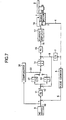
- FIG. 7 is a block diagram of the servo controlling device described in Japanese Patent Application No. H08-353627 (Japanese Unexamined Patent Publication No. H10-177407) applied by the present applicant.
- pulse counter 5 counts output pulses 4 outputted from pulse generator 3, and calculates and outputs a position feedback 6 of servo motor 1.
- F/V converter 7 calculates and outputs a speed feedback 8 of the servo motor based on the output pulses 7 of the pulse generator 3.
- a deviation between a position instruction 10 outputted from NC device 9 and the position feedback 6 is multiplied by a position loop gain Kp by multiplier 11, whereby a speed target value 12 is obtained.
- Integrator 14 integrates values that are obtained by multiplying a deviation between the speed target value 12 and speed feedback 8 by an integration gain 1/Ti or integration gain 1/Tih by multiplier 13 or multiplier 27. Furthermore, a deviation between a value resulting from integration by the integrator 14 and the speed feedback 8 is multiplied by a speed loop gain Kv by multiplier 15, whereby a torque instruction value 16 is obtained.
- Current amplifier 17 outputs a current 18 corresponding to the torque instruction 16 to the servo motor 1.
- Compensator 26 monitors the position instruction 10 outputted from the NC device 9, estimates a quadrant change timing by taking the position instruction 10 and the delay of the feed axis of the machine tool into account, and outputs a changeover signal 33 for changing the integration gain to be multiplied by the speed target value 12 from the integration gain 1/Ti to the integration gain 1/Tih.
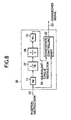
- Fig. 8 shows an equivalent control block diagram of this compensator 26.
- the compensator 26 comprises multipliers 11, 15, and 27, integrator 28, and change control part 32.
- the multiplier 11 multiplies the position instruction 10 by a position loop gain Kp.
- the multiplier 27 multiplies the output of the multiplier 11 by the integration gain 1/Tih.
- the integrator 28 integrates the output of the multiplier 27.
- the multiplier 15 multiplies the value integrated by the integrator 28 by a speed loop gain Kv to calculate an equivalent torque instruction 29.
- the changeover control part 32 detects a quadrant change based on the position instruction 20, and outputs a changeover signal 33 so that an integration gain by which the speed target value 12 is multiplied becomes an integration gain 1/Tih.
- a changeover signal 33 is outputted so that the integration gain by which the speed target value 12 is multiplied becomes an integration gain 1/Ti.
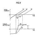
- Fig. 9 shows torque instruction and speed feedback waveforms (a) when the conventional method is used when changing a quadrant, torque instruction and speed feedback waveforms (b) in a case where following delay compensation is not applied, and an ideal speed feedback waveform (c) .
- the integration gain 1/Tih of the multiplier 27 is made larger than the integration gain 1/Ti of the multiplier 13, a torque instruction is quickly generated by which the integration gain 1/Ti of the speed loop is changed to the integration gain 1/Tih only during a period (d) in which the shaft stops to cancel static friction, a period (e) in which the shaft stops in the case where automatic following delay compensation is not applied is shortened to the period (d), whereby the speed feedback waveform is made closer to the ideal waveform (c).
- Fig. 7 shows an example of an I-P controlling method, however, there is also a case using a P-I controlling method.
- the equivalent control block and a control system which drives the feed axis may be different in operation from each other.
- the control system which drives the feed axis uses the integration gain 1/Tih of the integrator 27 during shaft stoppage, the control system becomes unstable, and the torque instruction vibrates or diverges.
- Fig. 11 shows examples of torque instructions when cutting is carried out with the same arc radius at arc instruction feed speeds of F1000 mm/min and F10000 mm/min without following delay compensation.
- (a) and (b) in Fig. 11 show torque instruction values when the shaft starts moving in a reverse direction at F1000 mm/min and F10000 mm/min, respectively, wherein the torque instruction value differs depending on the speed.
- the torque instruction value is fixed regardless of the speed, and as shown in Fig. 12, the value of the equivalent torque instruction 29 for terminating compensation is also fixed. Therefore, only a single, narrow-range speed can be accommodated, so that compensation effects at an out-of-range speed become insufficient or excessive.
- the abovementioned conventional controlling method has the following problems.
- An object of the invention is to provide a servo controlling device and method by which high-accuracy loci following control can be carried out by compensating a following delay of a servo system due to influence from friction occurring when a feed axis reverses its moving direction.
- a virtual internal model using constants separate from constants used in a control loop is configured, and avirtual torque instruction calculated in this virtual internal model is added to a torque instruction for driving the feed axis, and when this virtual torque instruction reaches a compensation terminating torque, the adding is terminated, and at this point, a value in an integrator inside the virtual internal model is added to a corresponding integrator of a position/speed feedback.
- the value of the abovementioned compensation terminating torque is determined as a function of time from the point of movement reversal detection.
- a servo controlling device which controls a motor based on an inputted position instruction, comprises:
- Cs(t) Fc 2 +(Cs(tz)-Fc 2 ) exp((tz-t)/et 2 ) + DcVfb(t) in a case where t > tz on the assumption that the motor speed is defined as Vfb(t), the viscous friction is defined as Dc, the Coulomb friction when the motor speed is positive is defined as Fc 1 , the Coulomb friction when the motor speed is negative is defined as Fc 2 , the value of an estimated disturbance Cs(t) at the timing tz is defined as Cs(tz), the time constant of the estimated disturbance Cs(t) when the motor decelerates and stops is defined as et 1 , and the time constant of the estimated disturbance Cs(t) when the motor that has decelerated and stopped and then accelerates is defined as et 2 ; and means for adding said estimated disturbance Cs(t) to the torque instruction.
- an estimated torque instruction is defined as T'ref(t)
- a weighting function is defined as w(t)
- friction parameters Cs(tz), et 1 , and et 2 in the estimated disturbance Cs(t) estimated within the disturbance compensating part are set by using a combination optimizing method such as a genetic algorithm to values which minimize an evaluation function J expressed by:
- an estimated disturbance Cs(T) is generated by using various parameters set in advance, and furthermore, friction parameters Cs(t), et 1 , and et 2 for determining an estimated disturbance Cs(t) are set by using a genetic algorithm, and therefore, disturbances including dynamic characteristics can be estimated with high accuracy. Therefore, disturbance compensation for a torque instruction in order to achieve high-accuracy following control can be optimally realized.
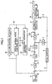
- Fig. 1 is a block diagram showing the construction of a servo controlling device of a first embodiment of the invention
- Fig. 2 is an equivalent control diagram of a virtual internal model computing unit 21 of Fig. 1
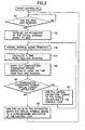
- Fig. 3 is a flowchart showing operation of the servo controlling device of Fig. 1
- Fig. 4 shows examples of compensation amount waveforms in a case where arcs having the same arc radius at feed speeds F1000 mm/min and F10000 mm/min are instructed in the servo controlling device of the first embodiment of the invention
- Fig. 5 is a block diagram showing the construction of a servo controlling device of a second embodiment of the invention
- Fig. 1 is a block diagram showing the construction of a servo controlling device of a first embodiment of the invention
- Fig. 2 is an equivalent control diagram of a virtual internal model computing unit 21 of Fig. 1
- Fig. 3 is a flowchart showing operation of the servo controlling device of Fig. 1
- FIG. 6 is a diagram showing changes in estimated disturbance Cs(t) outputted by a disturbance estimating part 7;
- Fig. 7 is a block diagram showing the construction of a conventional servo controlling device;
- Fig. 8 is an equivalent control block diagram of a compensator 26 in Fig. 7;
- Fig. 9 is an ideal speed and torque waveform chart when the conventional servo controlling device is used;
- Fig. 10 is a speed and torque waveform chart when the conventional servo controlling device is used and the torque vibrates;
- Fig. 11 is a diagram describing that a torque instruction waveform differs depending on the feed speed; and
- Fig. 12 is a compensation amount waveform chart of the conventional servo controlling device.
- Fig. 1 is a block diagram showing the construction of a servo controlling device of a first embodiment of the invention.
- Fig. 1 the same components as those in Fig. 7 are provided with the same reference numerals, and description thereof shall be omitted.
- the servo controlling device of the present embodiment is obtained by providing the conventional servo controlling device shown in Fig. 7 with a shaft reversal detector 19, a virtual internal model computing unit 21, and a compensation termination detector 23 in place of the compensator 26 and the multiplier 27.
- the feed axis reversal detector 19 outputs a shaft reversal signal 20 by using a position instruction 10.
- the virtual internal model computing unit 21 When the shaft reversal signal 20 is inputted, the virtual internal model computing unit 21 initializes a virtual internal model and outputs a virtual torque instruction 22 by using a position instruction 10.
- the compensation termination detector 23 detects compensation termination by using the virtual torque instruction 22 and a time function, and when compensation termination is not detected, the virtual torque instruction 22 is outputted as a compensation amount 24 to be added to a torque instruction of a control loop, and when compensation termination is detected, a value 34 of an integrator 31 that is used in the virtual internal model is outputted as a compensation amount 25 to be added to an integrator 14 of the control loop.
- Fig. 2 shows the construction of the virtual internal model computing unit 21. Actual compensation is carried out in a period from shaft stoppage to start of shaft reversal movement, and a feedback change at this point is almost zero or slight, so that the feedback change of the virtual internal model is ignored.
- This virtual internal model computing unit 21 comprises, as shown in Fig. 2, multipliers 11, 30, and 15 and integrator 31.
- An integration gain 1/Tih to be multiplied by the integrator 30 is set to be different from the integration gain 1/Ti (multiplier 13) of the control loop for driving the feed axis, and the same values as the position and speed loop gains used in the control loop for driving the feed axis are used for the position loop gain Kp of the multiplier 11 and the speed loop gain Kv of the multiplier 15.
- an inertia rigid body is set as a target to be controlled, however, it is also possible to design a more strict virtual internal model as a multiple inertial system by taking influence from viscous friction and disturbance into account.
- a formula for calculating a compensation terminating torque is described as a simplest linear function, however, functions such as a higher-degree function and an exponential function may be combined and used.
- a shaft reversal signal 20 is monitored, and reversal of the feed axis is in waiting (step 101).
- the integrator 14 of the virtual internal model is initialized to zero (step 102).
- operation of the virtual internal model is carried out by defining the input as a position instruction 10 to calculate a virtual torque instruction 22 (step 103).
- the time t from the feed axis reversal is calculated (step 104).
- a compensation terminating torque Limit is calculated (step 105).
- the compensation terminating torque Limit is compared with the virtual torque instruction 22 (step 106).
- the virtual torque instruction 22 is added to the torque instruction 16 of the control loop as a compensation amount 24 (step 107).
- the value 34 of the integrator 31 of the virtual internal model is added to the output value of the integrator 14 of the control loop as a compensation amount 25, and thereafter, compensation is terminated (step 108).
- a virtual internal model is configured, and a virtual torque instruction is added to a torque instruction of the control loop, whereby it becomes unnecessary to increase the integration gain of the control loop for driving the feed axis, and the torque does not greatly change even when feedback occurs. Therefore, a torque instruction for moving the feed axis in reverse can be smoothly and continuously generated without vibrations.
- a compensation amount optimum to a wide-range speed instruction and a position instruction generated based on an arc radius can be added to the torque instruction of the control loop.
- Fig. 4 shows examples of compensation amount waveforms when arcs with the same arc radius at feed speeds of F1000 mm/min and F10000 mm/min are instructed.
- (a) and (b) in Fig. 4 show, respectively, compensation amounts at the point of compensation termination when instructions of feed speeds of F1000 mm/min and F10000 mm/min are provided.
- a compensation amount 24 to be added to the torque instruction 16 is prepared by a compensator (comprising feed axis reversal detector 19, virtual internal model computing unit 21, and compensation termination detector 23) independent from the control loop by using a virtual internal model, so that stable compensation effects can be obtained. Furthermore, by determining optimum compensation terminating conditions with respect to a speed instruction by using a function of time from the point of shaft reversal, uniform compensation effects can be obtained for a wide-range speed instruction.
- the position instruction 10 is multiplied by a position loop gain Kp, and further multiplied by a certain integration gain 1/Tih, and then integrated, and multiplied by a speed loop gain Kv, whereby a compensation amount (virtual torque instruction 22) to be generated by the virtual internal model computing unit 21 is calculated based on a certain time function.
- a compensation amount virtual torque instruction 22
- no friction dynamic characteristics are taken into account in this compensation amount 24, so that it may not be an optimum value. Therefore, the setting must be repeatedly adjusted in order to obtain an optimum compensation amount 24, and furthermore, the setting of the integration gain 1/Tih and the time function is very difficult, and therefore, as a result, required control performance may not be obtained.
- the servo controlling device of the second embodiment is for solving such problems, which comprises, as shown in Fig. 5, position controlling part 41, speed controlling part 42, current controlling part 43, disturbance estimating part 47, differentiator 48, and subtracter 49.
- the position controlling part 41 inputs a position instruction Pref(t) and outputs a speed instruction Vref(t) to the speed controlling part 42 so that the motor position Pfb(t) corresponds to the position instruction Pref(t).
- the speed controlling part 42 inputs the speed instruction Vref, and outputs a torque instruction Tref(t)to the current controlling part 43 so that the motor speed Vfb(t) corresponds to the speed instruction Vref.
- the current controlling part 34 controls the current and drives the motor 44 based on the inputted torque instruction Tref(t).
- a mechanical part 45 is attached to the motor 44.
- a detector 46 detects the position of the rotor of the motor 44, and outputs the position as a motor position Pfb(t).
- the subtracter 48 outputs a value obtained by subtracting an estimated disturbance Cs(t) from the torque instruction Tref(t) to the current controller 43.
- the differentiator 48 calculates the speed of the motor 44 based on the motor position Pfb(t), and outputs the speed as Vfb(t).
- the disturbance estimating part 47 inputs the motor speed Vfb(t), and outputs an estimated disturbance Cs(t) calculated by using a predetermined formula to the subtracter 49.
- Formulas (2) and (3) for determining an estimated disturbance Cs(t) at the disturbance estimating part 47 are shown below.
- Cs(t) -Fc 1 +(Cs(tz)+Fc 1 ) exp((tz-t)/et 1 )-DcVfb(t) in a case where t ⁇ tz
- Cs(t) Fc 2 +(Cs(tz)-Fc 2 ) exp((tz-t)/et 2 )+DcVfb(t) in a case where t > tz
- the viscous friction Dc and Coulomb frictions Fc 1 and Fc 2 are determined in advance based on the actual characteristics of the motor 44.
- the Coulomb friction Fc 1 is a Coulomb friction when the motor speed Vfb(t) is positive
- the Coulomb friction Fc 2 is a Coulomb friction when the motor speed Vfb(t) is negative.
- Cs(tz), et 1 , and et 2 are parameters called friction parameters
- Cs(tz) is a value of an estimated disturbance Cs(t) at a timing tz
- et 1 and et 2 are time constants for determining an inclination of an increase or decrease in estimated disturbance Cs(t).
- w(t) shows a weighting function
- the section [a-b] indicates an evaluation period.
- a method for setting optimum parameters using a genetic algorithm for example, a method disclosed in "Determination of Optimum Control Gains" by Umeda and Oguro, Yaskawa Electric Corporation, Vol. 61, No. 237, p.222, 1997 may be used.
- the estimated disturbance Cs(t) that is outputted when the speed of the motor 44 is inverted grows exponentially at a time constant et 1 when the speed of the motor 44 decelerates toward zero from a predetermined speed, and becomes a negative inclination disturbance reaching the disturbance Cs(t) at the point at which the speed is zero.
- the estimated disturbance Cs(t) grows exponentially at a time constant et 2 from the disturbance Cs(tz) at the point at which the speed is zero, and continuously changes to a value determined by adding a viscous friction disturbance Dc and a Coulomb friction disturbance Fc 2 to the disturbance Cs(tz) at the point at which the speed is zero.
- friction parameters Cs(t), et 1 , and et 2 for determining the estimated disturbance Cs(t) are set by using a genetic algorithm, a disturbance containing dynamic characteristics can be estimated with high accuracy. Therefore, when it is demanded to realize highly accurate loci following control, disturbance compensation for torque instructions can be optimally realized. Furthermore, in the present embodiment, a genetic algorithm is used for selecting an optimum combination of friction parameters for the estimated disturbance Cs(t), however, other combination optimizing methods such as a learning control can be used.
Landscapes
- Engineering & Computer Science (AREA)
- Human Computer Interaction (AREA)
- Manufacturing & Machinery (AREA)
- Physics & Mathematics (AREA)
- General Physics & Mathematics (AREA)
- Automation & Control Theory (AREA)
- Control Of Position Or Direction (AREA)
- Feedback Control In General (AREA)
- Control Of Electric Motors In General (AREA)
- Numerical Control (AREA)
Abstract
Description
Cs(t) = -Fc1 +(Cs(tz)+Fc1) exp((t-tz)/et1) - DcVfb(t) in a case where t ≤ tz, or
means for adding said estimated disturbance Cs(t) to the torque instruction.

Formula (1) is a linear function of time using a compensation amount increase Delta Limit and a compensation amount offset Limit Offset based on time as constants.

Claims (5)
- A servo controlling method which has a control loop using a position/speed feedback and drives a feed axis of a machine tool, wherein
after a movement reversal of the feed axis is detected, a control loop is modeled, and a virtual internal model using constants of values that are different from those of the constants used in the control loop;
a virtual torque instruction calculated in the virtual internal model is added to a torque instruction for driving the feed axis;
when said virtual torque instruction reaches a predetermined value, said adding is terminated; and
when the adding is terminated, a value of an integrator within the virtual internal model at this point is added to a corresponding integrator of the position/speed feedback group. - The servo controlling method according to Claim 1, wherein the predetermined value is determined as a function of time from the point at which the movement removal is detected.
- A servo controlling device for controlling a motor based on an inputted position instruction, comprising:a position detecting part for detecting the position of a rotor of said motor as a motor position;a speed detecting part for detecting the speed of the motor;a position controlling part which outputs a speed instruction so that the motor position corresponds to said position instruction;a speed controlling part which outputs a torque instruction so that the motor speed corresponds to said speed instruction;a current controlling part which inputs said torque instruction and drives the motor by controlling a current;a disturbance estimating part which estimates a motor stop timing tz when detecting that the motor speed has become zero by monitoring the motor speed, and outputs an estimated disturbance Cs(t) calculated by
Cs(t) = -Fc1 +(Cs(tz)+Fc1) exp((t-tz)/et1) - DcVfb(t) in a case where t ≤ tz, or
Cs(t) = Fc2+ (Cs(tz)-Fc2) exp((tz-t)/et2) + DcVfb(t) in a case where t > tz, provided that the motor speed is defined as Vfb(t), the viscous friction is defined as Dc, the Coulomb friction when the motor speed is positive is defined as Fc1, the Coulomb friction when the motor speed is negative is defined as Fc2, a value of an estimated disturbance at the timing tz is defined as Cs(tz), a time constant of the estimated disturbance Cs (t) when the motor decelerates and stops is defined as et1, and a time constant of the estimated disturbance Cs(t) when the motor accelerates is defined as et2; andmeans for adding the estimated disturbance Cs(t) to the torque instruction. - The servo controlling device according to Claim 3, wherein
friction parameters Cs(tz), et1, and et2 in the estimated disturbance Cs(t) estimated in the disturbance estimating part are set by using a combination optimizing method to values which minimize an evaluation function J expressed by
- The servo controlling device according to Claim 4, wherein said combination optimizing method is a genetic algorithm.
Applications Claiming Priority (3)
| Application Number | Priority Date | Filing Date | Title |
|---|---|---|---|
| JP2000086651 | 2000-03-27 | ||
| JP2000086651A JP3552988B2 (en) | 1999-11-29 | 2000-03-27 | Servo control method |
| PCT/JP2001/002427 WO2001073517A1 (en) | 2000-03-27 | 2001-03-26 | Servo controlling device and method |
Publications (3)
| Publication Number | Publication Date |
|---|---|
| EP1271274A1 true EP1271274A1 (en) | 2003-01-02 |
| EP1271274A4 EP1271274A4 (en) | 2005-01-12 |
| EP1271274B1 EP1271274B1 (en) | 2008-10-08 |
Family
ID=18602779
Family Applications (1)
| Application Number | Title | Priority Date | Filing Date |
|---|---|---|---|
| EP01915794A Expired - Lifetime EP1271274B1 (en) | 2000-03-27 | 2001-03-26 | Servo controlling device and method |
Country Status (5)
| Country | Link |
|---|---|
| US (1) | US7050862B2 (en) |
| EP (1) | EP1271274B1 (en) |
| JP (1) | JP3552988B2 (en) |
| DE (1) | DE60136056D1 (en) |
| WO (1) | WO2001073517A1 (en) |
Families Citing this family (14)
| Publication number | Priority date | Publication date | Assignee | Title |
|---|---|---|---|---|
| US6947748B2 (en) * | 2000-12-15 | 2005-09-20 | Adaptix, Inc. | OFDMA with adaptive subcarrier-cluster configuration and selective loading |
| JP4043996B2 (en) * | 2003-01-20 | 2008-02-06 | ファナック株式会社 | Servo motor drive control device |
| JP2005301508A (en) * | 2004-04-08 | 2005-10-27 | Fanuc Ltd | Control unit |
| JP4538786B2 (en) * | 2004-04-09 | 2010-09-08 | 株式会社安川電機 | Motor control device |
| JP2005348536A (en) * | 2004-06-03 | 2005-12-15 | Yaskawa Electric Corp | Servo control device and adjustment method |
| DE102005036848B4 (en) * | 2005-08-04 | 2007-11-22 | Siemens Ag | Method and device for motion control of a movable machine element of a machine |
| JP5012075B2 (en) * | 2007-02-15 | 2012-08-29 | 横河電機株式会社 | Process control device |
| JP4685071B2 (en) * | 2007-08-08 | 2011-05-18 | 住友重機械工業株式会社 | Motor control device and motor control method |
| JP5139164B2 (en) * | 2008-06-10 | 2013-02-06 | オークマ株式会社 | Position control device |
| JP5850639B2 (en) * | 2011-05-09 | 2016-02-03 | 富士機械製造株式会社 | Control parameter adjustment method and control parameter adjustment system for position control device |
| JP6065372B2 (en) * | 2012-02-10 | 2017-01-25 | セイコーエプソン株式会社 | Motor control device, robot hand and robot |
| JP6325504B2 (en) * | 2015-10-28 | 2018-05-16 | ファナック株式会社 | Servo control device having a function of automatically adjusting a learning controller |
| WO2018095530A1 (en) * | 2016-11-24 | 2018-05-31 | Renesas Electronics Europe Gmbh | Adaptive control system |
| CN109342428B (en) * | 2018-11-19 | 2023-10-20 | 蚌埠市科达电器有限公司 | Digital imaging detection controller |
Family Cites Families (11)
| Publication number | Priority date | Publication date | Assignee | Title |
|---|---|---|---|---|
| US5036266A (en) * | 1989-01-17 | 1991-07-30 | Tektronix, Inc. | Mass velocity controller |
| JP2637578B2 (en) * | 1989-11-08 | 1997-08-06 | オークマ株式会社 | Machine tool position control device |
| JP2882863B2 (en) | 1990-04-17 | 1999-04-12 | 三菱重工業株式会社 | Servo control device |
| JP2709773B2 (en) * | 1992-02-05 | 1998-02-04 | ファナック株式会社 | Servo motor control method |
| JPH09167023A (en) | 1995-12-15 | 1997-06-24 | Yaskawa Electric Corp | Servo control method |
| JPH09282008A (en) | 1996-04-15 | 1997-10-31 | Fuji Xerox Co Ltd | Servo controller |
| JP3918884B2 (en) | 1996-12-16 | 2007-05-23 | 株式会社安川電機 | Servo control method |
| JPH11102211A (en) * | 1997-09-25 | 1999-04-13 | Toshiba Mach Co Ltd | Method and device for servo control |
| JP3446595B2 (en) * | 1998-03-30 | 2003-09-16 | 三菱電機株式会社 | Servo device |
| JP2936261B1 (en) | 1998-03-31 | 1999-08-23 | セイコー精機株式会社 | Processing equipment with friction force estimation function |
| US6744233B1 (en) * | 2000-11-01 | 2004-06-01 | Mitsubishi Denki Kabushiki Kaisha | Servo controller and method |
-
2000
- 2000-03-27 JP JP2000086651A patent/JP3552988B2/en not_active Expired - Fee Related
-
2001
- 2001-03-26 EP EP01915794A patent/EP1271274B1/en not_active Expired - Lifetime
- 2001-03-26 US US10/239,776 patent/US7050862B2/en not_active Expired - Fee Related
- 2001-03-26 WO PCT/JP2001/002427 patent/WO2001073517A1/en not_active Ceased
- 2001-03-26 DE DE60136056T patent/DE60136056D1/en not_active Expired - Lifetime
Also Published As
| Publication number | Publication date |
|---|---|
| US7050862B2 (en) | 2006-05-23 |
| JP3552988B2 (en) | 2004-08-11 |
| EP1271274B1 (en) | 2008-10-08 |
| EP1271274A4 (en) | 2005-01-12 |
| US20030139824A1 (en) | 2003-07-24 |
| DE60136056D1 (en) | 2008-11-20 |
| JP2001222303A (en) | 2001-08-17 |
| WO2001073517A1 (en) | 2001-10-04 |
Similar Documents
| Publication | Publication Date | Title |
|---|---|---|
| US7050862B2 (en) | Servo controlling device and method | |
| EP0967535B1 (en) | Position controller | |
| US5159254A (en) | Numerical control unit for estimating movement parameters using a model | |
| EP1437637B1 (en) | Servomotor controller | |
| CN103262404B (en) | Real-time controller of servo motor based on load weight | |
| EP1496412B1 (en) | Positioning servocontroller | |
| US4727303A (en) | Positional control method and system utilizing same | |
| Altintas et al. | Sliding mode controller design for high speed feed drives | |
| EP0827265A1 (en) | Apparatus for determination of control constant | |
| CN101753094A (en) | Inertia estimating controller and control system | |
| JP4424350B2 (en) | POSITION CONTROL DEVICE AND ITS CONTROL METHOD | |
| US7638965B2 (en) | Motor control apparatus | |
| JP3370040B2 (en) | Speed control device | |
| JPH06339292A (en) | Force controlling method by estimation of disturbance load | |
| CN114123906A (en) | Permanent magnet synchronous motor inertia identification method and system and storage medium | |
| JP5660482B2 (en) | Control method and control device for feed drive system of machine tool | |
| JP4538786B2 (en) | Motor control device | |
| JP2005304155A5 (en) | ||
| JPH06165550A (en) | Electric motor control method and electric motor control device | |
| JP4053529B2 (en) | Motor speed control device | |
| JP2009031989A (en) | Servo control device | |
| JP2738115B2 (en) | Acceleration / deceleration control device | |
| JP2003084839A (en) | Motor control device with overshoot suppression function | |
| JPH11155294A (en) | Motor drive | |
| JP3982308B2 (en) | Positioning control device |
Legal Events
| Date | Code | Title | Description |
|---|---|---|---|
| PUAI | Public reference made under article 153(3) epc to a published international application that has entered the european phase |
Free format text: ORIGINAL CODE: 0009012 |
|
| 17P | Request for examination filed |
Effective date: 20020926 |
|
| AK | Designated contracting states |
Kind code of ref document: A1 Designated state(s): AT BE CH CY DE DK ES FI FR GB GR IE IT LI LU MC NL PT SE TR |
|
| AX | Request for extension of the european patent |
Free format text: AL;LT;LV;MK;RO;SI |
|
| RBV | Designated contracting states (corrected) |
Designated state(s): DE |
|
| A4 | Supplementary search report drawn up and despatched |
Effective date: 20041126 |
|
| RIC1 | Information provided on ipc code assigned before grant |
Ipc: 7G 05D 3/12 A Ipc: 7G 05B 19/19 B Ipc: 7B 23Q 5/10 B |
|
| 17Q | First examination report despatched |
Effective date: 20060926 |
|
| GRAP | Despatch of communication of intention to grant a patent |
Free format text: ORIGINAL CODE: EPIDOSNIGR1 |
|
| GRAS | Grant fee paid |
Free format text: ORIGINAL CODE: EPIDOSNIGR3 |
|
| GRAA | (expected) grant |
Free format text: ORIGINAL CODE: 0009210 |
|
| AK | Designated contracting states |
Kind code of ref document: B1 Designated state(s): DE |
|
| REF | Corresponds to: |
Ref document number: 60136056 Country of ref document: DE Date of ref document: 20081120 Kind code of ref document: P |
|
| PLBE | No opposition filed within time limit |
Free format text: ORIGINAL CODE: 0009261 |
|
| STAA | Information on the status of an ep patent application or granted ep patent |
Free format text: STATUS: NO OPPOSITION FILED WITHIN TIME LIMIT |
|
| 26N | No opposition filed |
Effective date: 20090709 |
|
| PGFP | Annual fee paid to national office [announced via postgrant information from national office to epo] |
Ref country code: DE Payment date: 20160322 Year of fee payment: 16 |
|
| REG | Reference to a national code |
Ref country code: DE Ref legal event code: R119 Ref document number: 60136056 Country of ref document: DE |
|
| PG25 | Lapsed in a contracting state [announced via postgrant information from national office to epo] |
Ref country code: DE Free format text: LAPSE BECAUSE OF NON-PAYMENT OF DUE FEES Effective date: 20171003 |