EP1271217A1 - Occulaire à réglage dioptrique intégré, pour tête de visée de giravion - Google Patents
Occulaire à réglage dioptrique intégré, pour tête de visée de giravion Download PDFInfo
- Publication number
- EP1271217A1 EP1271217A1 EP02291529A EP02291529A EP1271217A1 EP 1271217 A1 EP1271217 A1 EP 1271217A1 EP 02291529 A EP02291529 A EP 02291529A EP 02291529 A EP02291529 A EP 02291529A EP 1271217 A1 EP1271217 A1 EP 1271217A1
- Authority
- EP
- European Patent Office
- Prior art keywords
- ring
- eyepiece
- adjustment
- thread
- lever
- Prior art date
- Legal status (The legal status is an assumption and is not a legal conclusion. Google has not performed a legal analysis and makes no representation as to the accuracy of the status listed.)
- Withdrawn
Links
- 238000007789 sealing Methods 0.000 claims abstract description 12
- 230000001105 regulatory effect Effects 0.000 abstract 2
- 210000001061 forehead Anatomy 0.000 description 10
- 210000003128 head Anatomy 0.000 description 9
- 230000000295 complement effect Effects 0.000 description 2
- 238000006073 displacement reaction Methods 0.000 description 2
- 239000006260 foam Substances 0.000 description 2
- 238000000034 method Methods 0.000 description 2
- 230000002093 peripheral effect Effects 0.000 description 2
- 230000000903 blocking effect Effects 0.000 description 1
- 230000015556 catabolic process Effects 0.000 description 1
- 238000010276 construction Methods 0.000 description 1
- 238000006731 degradation reaction Methods 0.000 description 1
- 230000000694 effects Effects 0.000 description 1
- 238000010304 firing Methods 0.000 description 1
- 230000003287 optical effect Effects 0.000 description 1
- 230000002028 premature Effects 0.000 description 1
Images


Classifications
-
- G—PHYSICS
- G02—OPTICS
- G02B—OPTICAL ELEMENTS, SYSTEMS OR APPARATUS
- G02B25/00—Eyepieces; Magnifying glasses
- G02B25/001—Eyepieces
-
- G—PHYSICS
- G02—OPTICS
- G02B—OPTICAL ELEMENTS, SYSTEMS OR APPARATUS
- G02B7/00—Mountings, adjusting means, or light-tight connections, for optical elements
- G02B7/02—Mountings, adjusting means, or light-tight connections, for optical elements for lenses
- G02B7/04—Mountings, adjusting means, or light-tight connections, for optical elements for lenses with mechanism for focusing or varying magnification
Definitions
- the invention relates to an eyepiece with integrated dioptric adjustment, intended to be mounted on an aiming head fitted to a rotorcraft.
- the invention applies in particular to an eyepiece mounted on an aiming head of a helicopter fire line.
- the aiming head comprises usually a box mainly located above from the roof of the helicopter's cell.
- One arm carries eyepiece, terminated by an eyepiece, is mounted on the housing, inside the cell, to allow an observer placed in it to observe a target placed outside the helicopter.
- the eyepiece is provided a dioptric adjustment ring, which cooperates with a fixed part of the eyepiece via a large thread. So the rotation of the ring adjustment allows the observer to adjust the eyepiece to his view.
- the rotation of the adjusting ring is generally ensured manually, by acting on splines machined on its outer surface.
- the adjustment stroke complete usually corresponds to a half-turn of the Ring.
- a sealing bellows is generally placed between the adjustment ring and the fixed part of the eyepiece, to ensure protection thread.
- a foam front support encompasses usually the eyepiece, so as to be interposed between these and the observer's face.
- the forehead support structure is such that it covers almost completely the eyepiece in certain positions ring adjustment.
- the space available between the forehead support and the sealing bellows is insufficient to avoid the observer's glove overflows on the bellows when he grasps the grooved adjustment ring.
- the sealing bellows deteriorates quickly to use if no special precautions is not taken.
- the subject of the invention is precisely a eyepiece with integrated dioptric adjustment, for a aircraft sighting, whose original design allows make an adjustment with a gloved hand, without removal of the forehead support and without risk of damage prematurely the sealing bellows which ensures the thread protection.
- a sighting head eyepiece rotorcraft comprising a fixed part provided with a thread, a diopter adjustment ring engaged on said thread, a sealing bellows covering the thread between a rear edge of the ring and said fixed part, and a forehead support capable of covering a front part of the eyepiece, characterized in that the diopter adjustment ring carries a control lever of rotation, which projects radially towards the outside between the sealing bellows and the support forehead.
- the observer can make a diopter adjustment using gloves and without removing the forehead support, i.e. when the helicopter is in flight, acting directly on the lever secured to the adjustment ring. A premature degradation of the sealing bellows which protects the thread is thus avoided.
- control lever is fixed on a control ring which surrounds the ring adjustment and has interlocking internal splines on the outer grooves of said ring setting.
- control lever is attached directly on the diopter adjustment ring.
- FIG 1 there is shown schematically the front part of a helicopter. This includes a cell 10 whose roof supports a sighting head 12 of a shooting line (not shown).
- the sighting head 12 comprises a housing 14 of which a main part 16 is situated above the roof of cell 10, outside the helicopter. Another part 18 of the housing 14 is located at inside the cockpit 20 of the helicopter. An eyepiece arm 22 terminated by an eyepiece 24 is mounted on the part 18 of the housing 14, to allow an observer placed in the cabin 20 to use the aiming head 12.
- Parts 16 and 18 of the housing 14 and the arm eyepiece holder 22 used to house various components optics (not shown) allowing an observer looking through eyepiece 24 to observe a scene.
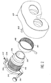
- the eyepiece 24 comprises a fixed part 26 provided with a long pitch thread (not shown) on its surface exterior.
- a dioptric adjustment ring 28 is mounted around the fixed part 26. More specifically, the ring adjustment 28 has an internal thread (not shown) complementary to the external thread of the fixed part 26, so as to be engaged thereon through said threads.
- the eyepiece 24 can be adjusted to the view of the observer by a rotation of the adjusting ring 28. Indeed, this rotation has the effect of moving the adjustment ring 28 parallel to its axis, with respect to the part fixed eyepiece 24. Axial displacement of the ring adjustment 28 results in displacement corresponding to a set of lenses 30 carried by said ring, which ensures the desired adjustment.
- eyepiece 24 also includes a bellows 32.
- This bellows 32 protects the external thread of the fixed part 26. For this purpose, it surrounds the portion of this thread which is included between said fixed part and a rear edge of the ring 28.
- front and rear mean respectively parts close to or, on the contrary, distant from the eye of the observer.
- a support 34 in the form of a necklace is fixed on the part fixed 26 of the eyepiece 24.
- the fixing can in particular be secured by tightening, using a screw 36.
- the support 34 is provided with a part tubular 38, of hexagonal section, oriented parallel to the optical axis of the eyepiece 24 and its position is suitable for use with right eye or eye left of the forehead support, following the directing eye of the observer.
- the eyepiece 24 is designed to be equipped with a common front support 40, removable and made of foam.
- the front support 40 is fixed on the support 34, on the front side of the eyepieces 24, so as to surround and cover the adjusting ring 28 forwards, leaving the end of the eyepiece open 24.
- the front support 40 comprises a rod 42, comprising two dishes corresponding to the fixing screw 44.
- the rod 42 is received in the tubular part 38.
- the blocking of the rod 42 is provided by a screw 44. More specifically, the screw 44 is screwed into a threaded hole through the wall of the tubular part 38 and its end bears against the outer surface of the rod 42.
- the eyepiece 24 is an existing eyepiece.
- the adjusting ring 28 then has, on its surface outer device, splines 46.
- a control ring 48 is mounted around the adjustment ring 28.
- the control ring 48 also has, on its peripheral surface interior, grooves 50 complementary to the splines 46 formed on the adjusting ring 28.
- the control ring 48 is integral with rotation of the adjusting ring 28.
- the ring control 48 carries a lever 52 for controlling rotation. More specifically, the lever 52 for controlling the rotation is integral with the control ring 48 and made radially outwardly projecting between the bellows 32 and the front support 40, as shown in especially Figure 3.
- lever 52 of rotation control is fixed near the edge rear of control ring 48, to account the fact that in an extreme position of the ring setting 28 illustrated on the right in FIG. 3, the ring and the control ring are almost fully recessed in the front support 40.
- the mounting of the ring control 48 on the adjusting ring 28 is achieved differently depending on whether the eyepiece relates to the right eye or the observer's left eye.
- the lever 52 must always be accessible to outside the monocular system, regardless of adjustment made, taking into account that the adjustment stroke of each eyepiece 24 is one turn around.
- This arrangement allows a user to control a rotation of the adjusting ring 28 in acting on the lever 52 for controlling rotation.
- the user can thus make an adjustment eyepiece diopter 24 without removing the forehead support 40 and without risking damaging the sealing bellows 32, even if fitted with gloves as is generally the case when the helicopter is in flight.
- the control lever 52 can be fixed directly on the diopter adjustment ring 28.
- the adjusting ring 28 can then be equipped with two tapped holes (corresponding respectively at the right eye and left eye positions).
- the control lever 52 is terminated by a threaded rod intended to be screwed into one of the tapped holes in the adjusting ring 28.
Landscapes
- Physics & Mathematics (AREA)
- General Physics & Mathematics (AREA)
- Optics & Photonics (AREA)
- Telescopes (AREA)
Abstract
Description
L'invention s'applique notamment à un oculaire monté sur une tête de visée d'une conduite de tir d'hélicoptère.
- la figure 1 est une vue de côté, qui représente schématiquement la partie avant d'un hélicoptère équipé d'une tête de visée dont les oculaires sont réalisés conformément à l'invention ;
- la figure 2 est une vue en perspective éclatée d'un oculaire illustrant un mode de réalisation préféré de l'invention ;
- la figure 3 est une vue de dessus, en coupe partielle, de l'oculaire de la figure 2, la figure représentant les deux positions extrêmes du réglage dioptrique.
Claims (3)
- Oculaire (24) de tête de visée de giravion, comprenant une partie fixe (26) munie d'un filetage, une bague (28) de réglage dioptrique en prise sur ledit filetage, un soufflet d'étanchéité (32) recouvrant le filetage entre un bord arrière de la bague (28) et ladite partie fixe (26), et un appui front (40) apte à recouvrir une partie avant de l'oculaire (24), caractérisé en ce que la bague (28) de réglage dioptrique porte un levier (52) de commande de rotation, qui fait saillie radialement vers l'extérieur entre le soufflet d'étanchéité (32) et l'appui front (40).
- Oculaire selon la revendication 1, dans lequel la bague (28) de réglage dioptrique comporte des cannelures extérieures (46) et le levier de commande (52) est fixé sur une bague de commande (48) qui entoure la bague de réglage (28) et comporte des cannelures intérieures (50) en prise sur les cannelures extérieures (46) de ladite bague de réglage (28).
- Oculaire selon la revendication 1, dans lequel le levier de commande (52) est fixé directement sur la bague de réglage dioptrique (28).
Applications Claiming Priority (2)
| Application Number | Priority Date | Filing Date | Title |
|---|---|---|---|
| FR0108167 | 2001-06-21 | ||
| FR0108167A FR2826460B1 (fr) | 2001-06-21 | 2001-06-21 | Oculaire a reglage dioptrique integre, pour tete de visee de giravion |
Publications (1)
| Publication Number | Publication Date |
|---|---|
| EP1271217A1 true EP1271217A1 (fr) | 2003-01-02 |
Family
ID=8864592
Family Applications (1)
| Application Number | Title | Priority Date | Filing Date |
|---|---|---|---|
| EP02291529A Withdrawn EP1271217A1 (fr) | 2001-06-21 | 2002-06-19 | Occulaire à réglage dioptrique intégré, pour tête de visée de giravion |
Country Status (2)
| Country | Link |
|---|---|
| EP (1) | EP1271217A1 (fr) |
| FR (1) | FR2826460B1 (fr) |
Families Citing this family (1)
| Publication number | Priority date | Publication date | Assignee | Title |
|---|---|---|---|---|
| CN111258020B (zh) * | 2020-01-14 | 2021-05-18 | 中国科学院长春光学精密机械与物理研究所 | 螺纹锁紧结构及调焦镜头组件 |
Citations (3)
| Publication number | Priority date | Publication date | Assignee | Title |
|---|---|---|---|---|
| US4616907A (en) * | 1984-04-13 | 1986-10-14 | Enshu Kogaku Seiki Company Limited | Zooming mechanism for compact binoculars |
| US4712897A (en) * | 1985-07-27 | 1987-12-15 | Ernst Leitz Wetzlar Gmbh | Device for adjustment of the viewfinder eyepiece of a camera |
| US4818086A (en) * | 1988-03-09 | 1989-04-04 | Bausch & Lomb Incorporated | Focus lock for binoculars |
-
2001
- 2001-06-21 FR FR0108167A patent/FR2826460B1/fr not_active Expired - Lifetime
-
2002
- 2002-06-19 EP EP02291529A patent/EP1271217A1/fr not_active Withdrawn
Patent Citations (3)
| Publication number | Priority date | Publication date | Assignee | Title |
|---|---|---|---|---|
| US4616907A (en) * | 1984-04-13 | 1986-10-14 | Enshu Kogaku Seiki Company Limited | Zooming mechanism for compact binoculars |
| US4712897A (en) * | 1985-07-27 | 1987-12-15 | Ernst Leitz Wetzlar Gmbh | Device for adjustment of the viewfinder eyepiece of a camera |
| US4818086A (en) * | 1988-03-09 | 1989-04-04 | Bausch & Lomb Incorporated | Focus lock for binoculars |
Also Published As
| Publication number | Publication date |
|---|---|
| FR2826460A1 (fr) | 2002-12-27 |
| FR2826460B1 (fr) | 2003-09-26 |
Similar Documents
| Publication | Publication Date | Title |
|---|---|---|
| CA2349764C (fr) | Perfectionnement pour casque de protection | |
| EP1345505B1 (fr) | Casque a visieres escamotables a reconfiguration rapide jour/nuit | |
| EP3404176A1 (fr) | Dispositif de déverrouillage d'un serrure de porte | |
| FR2691051A1 (fr) | Dispositif de fixation d'une paire de lunettes à un couvre-chef. | |
| WO2016083696A1 (fr) | Outil électroportatif à transmission protégée | |
| FR2724541A1 (fr) | Paire d'articulations a manoeuvres synchronisees pour la fixation d'une visiere escamotable sur un casque | |
| EP0777847B1 (fr) | Dispositif d'adaptation d'un accessoire d'aide au tir sur une arme a feu individuelle | |
| WO2021058921A1 (fr) | Telescope equipe d'un dispositif de reglage de l'inclinaison et de la position d'un miroir | |
| CA2225618A1 (fr) | Dispositif de pivot entre un element mobile et une structure fixe accessible d'un seul cote | |
| FR2826460A1 (fr) | Oculaire a reglage dioptrique integre, pour tete de visee de giravion | |
| EP1895865B1 (fr) | Dispositif de fixation d'une visiere sur une coque de casque | |
| FR2560753A1 (fr) | Casque a visiere, notamment pour pilote d'aeronef | |
| EP0553033B1 (fr) | Dispositif de fixation et de raccordement, notamment d'un ensemble intensificateur de lumière sur un générateur d'images d'un viseur de casque pilote | |
| EP3555549B1 (fr) | Crosse articulee pour arme a appui d'epaule | |
| EP1177474B1 (fr) | Dispositif optronique muni d'un miroir de mise au point pour projection sur visiere | |
| FR2778237A1 (fr) | Perfectionnements au montage des dispositifs de visee d'armes | |
| EP1262729A1 (fr) | Tête de visée à pointeur laser intégré, pour un aéronef tel qu'un giravion | |
| EP0350396B1 (fr) | Système mécanique de recopie d'une position angulaire | |
| EP1813478B1 (fr) | Dispositif formant support réglable | |
| EP2288540B1 (fr) | Dispositif d'accouplement a platine de reglage | |
| FR2577312A1 (fr) | Dispositif de visee pour arme individuelle. | |
| EP0990833A1 (fr) | Support mural pour boítier de caméra de télévision | |
| EP3372747B1 (fr) | Structure de store | |
| EP1801673B1 (fr) | Dispositif de sécurité pour un mécanisme de commande d'une montre | |
| FR3055270B1 (fr) | Console centrale pour habitacle de vehicule automobile. |
Legal Events
| Date | Code | Title | Description |
|---|---|---|---|
| PUAI | Public reference made under article 153(3) epc to a published international application that has entered the european phase |
Free format text: ORIGINAL CODE: 0009012 |
|
| AK | Designated contracting states |
Kind code of ref document: A1 Designated state(s): AT BE CH CY DE DK ES FI FR GB GR IE IT LI LU MC NL PT SE TR |
|
| AX | Request for extension of the european patent |
Free format text: AL;LT;LV;MK;RO;SI |
|
| 17P | Request for examination filed |
Effective date: 20030310 |
|
| AKX | Designation fees paid |
Designated state(s): AT BE CH CY DE DK ES FI FR GB GR IE IT LI LU MC NL PT SE TR |
|
| GRAP | Despatch of communication of intention to grant a patent |
Free format text: ORIGINAL CODE: EPIDOSNIGR1 |
|
| STAA | Information on the status of an ep patent application or granted ep patent |
Free format text: STATUS: THE APPLICATION IS DEEMED TO BE WITHDRAWN |
|
| 18D | Application deemed to be withdrawn |
Effective date: 20040828 |