EP1271027A2 - Valve device - Google Patents
Valve device Download PDFInfo
- Publication number
- EP1271027A2 EP1271027A2 EP02012814A EP02012814A EP1271027A2 EP 1271027 A2 EP1271027 A2 EP 1271027A2 EP 02012814 A EP02012814 A EP 02012814A EP 02012814 A EP02012814 A EP 02012814A EP 1271027 A2 EP1271027 A2 EP 1271027A2
- Authority
- EP
- European Patent Office
- Prior art keywords
- valve
- block
- media
- valve arrangement
- control
- Prior art date
- Legal status (The legal status is an assumption and is not a legal conclusion. Google has not performed a legal analysis and makes no representation as to the accuracy of the status listed.)
- Granted
Links
Images

Classifications
-
- G—PHYSICS
- G21—NUCLEAR PHYSICS; NUCLEAR ENGINEERING
- G21C—NUCLEAR REACTORS
- G21C9/00—Emergency protection arrangements structurally associated with the reactor, e.g. safety valves provided with pressure equalisation devices
-
- F—MECHANICAL ENGINEERING; LIGHTING; HEATING; WEAPONS; BLASTING
- F15—FLUID-PRESSURE ACTUATORS; HYDRAULICS OR PNEUMATICS IN GENERAL
- F15B—SYSTEMS ACTING BY MEANS OF FLUIDS IN GENERAL; FLUID-PRESSURE ACTUATORS, e.g. SERVOMOTORS; DETAILS OF FLUID-PRESSURE SYSTEMS, NOT OTHERWISE PROVIDED FOR
- F15B13/00—Details of servomotor systems ; Valves for servomotor systems
- F15B13/02—Fluid distribution or supply devices characterised by their adaptation to the control of servomotors
- F15B13/06—Fluid distribution or supply devices characterised by their adaptation to the control of servomotors for use with two or more servomotors
- F15B13/08—Assemblies of units, each for the control of a single servomotor only
- F15B13/0803—Modular units
- F15B13/0807—Manifolds
- F15B13/0817—Multiblock manifolds
-
- F—MECHANICAL ENGINEERING; LIGHTING; HEATING; WEAPONS; BLASTING
- F16—ENGINEERING ELEMENTS AND UNITS; GENERAL MEASURES FOR PRODUCING AND MAINTAINING EFFECTIVE FUNCTIONING OF MACHINES OR INSTALLATIONS; THERMAL INSULATION IN GENERAL
- F16K—VALVES; TAPS; COCKS; ACTUATING-FLOATS; DEVICES FOR VENTING OR AERATING
- F16K17/00—Safety valves; Equalising valves, e.g. pressure relief valves
- F16K17/02—Safety valves; Equalising valves, e.g. pressure relief valves opening on surplus pressure on one side; closing on insufficient pressure on one side
- F16K17/04—Safety valves; Equalising valves, e.g. pressure relief valves opening on surplus pressure on one side; closing on insufficient pressure on one side spring-loaded
- F16K17/10—Safety valves; Equalising valves, e.g. pressure relief valves opening on surplus pressure on one side; closing on insufficient pressure on one side spring-loaded with auxiliary valve for fluid operation of the main valve
-
- Y—GENERAL TAGGING OF NEW TECHNOLOGICAL DEVELOPMENTS; GENERAL TAGGING OF CROSS-SECTIONAL TECHNOLOGIES SPANNING OVER SEVERAL SECTIONS OF THE IPC; TECHNICAL SUBJECTS COVERED BY FORMER USPC CROSS-REFERENCE ART COLLECTIONS [XRACs] AND DIGESTS
- Y02—TECHNOLOGIES OR APPLICATIONS FOR MITIGATION OR ADAPTATION AGAINST CLIMATE CHANGE
- Y02E—REDUCTION OF GREENHOUSE GAS [GHG] EMISSIONS, RELATED TO ENERGY GENERATION, TRANSMISSION OR DISTRIBUTION
- Y02E30/00—Energy generation of nuclear origin
- Y02E30/30—Nuclear fission reactors
Definitions
- the invention relates to a valve arrangement with a shut-off block on which a Safety valve and one with this over a number of led in the shut-off block Media lines communicating control valve are arranged.
- Pressure-carrying components or units of technical systems such as the pressure vessel of a nuclear facility are common by means of safety valves against the occurrence of excess design pressures secured in their interior.
- the pressure vessel a nuclear plant usually has a number of safety valves assigned, which when a predetermined limit pressure in the Release the pressure vessel through a blow-off path. If necessary, via the blow-off path relaxation of the pressure vessel to a pressure level below a limit pressure which is considered admissible.
- safety valves in nuclear plants is due to the prevailing there Comparatively, requirements for operational safety and care compliance strict regulations regarding reliability and reproducibility the closing behavior of the safety valves is also required.
- a such a safety valve can be coupled to a control valve, which in turn can in turn comprise a main control module and a pilot control module.
- a control valve which in turn can in turn comprise a main control module and a pilot control module.
- a valve arrangement is known from DE 196 28 610 C1, which is particularly suitable for is suitable for use in a nuclear power plant.
- This valve assembly includes a safety valve and a pilot and a main control module Control unit, also known as a control valve.
- Both the safety valve and the control valve of the known valve arrangement are according to the so-called Relief principle designed, the closed state of the safety valve and also the control valve with a suitable application high pressure is maintained from a pressurized system. If at this valve arrangement the contact pressure of the control valve is exceeded, so a blow-off system is opened via a pressure-displacement converter Control valve, which leads to relief of a control chamber of the control valve.
- Such a valve arrangement can comprise a so-called shut-off block, on which the safety valve and the control valve are mounted.
- this block are usually the media lines through which the safety valve communicates with the control valve.
- These include media lines the relief lines mentioned, via which the control rooms of the control valve and the safety valve are relieved of pressure, as well as impulse lines for forwarding the pressure from the pressure vessel to be protected and / or Filling lines through which the control rooms after actuation of the respective Valve can be pressurized again.
- valve arrangements are usually safety-relevant Components in a nuclear facility. Because of this and because of the Strict safety precautions to be observed when used in a nuclear facility are such valve arrangements when used in a nuclear plant usually subjected to a variety of functional tests. This is usually after the installation of such a valve arrangement Initially, a so-called adjustment test is provided, in which the basic settings the respective valve arrangement such as the response pressure, spring forces or travel with regard to the existing requirements or in With regard to the special requirements of each system. In addition, functional tests of all individual components can be carried out the valve arrangement as well as recurrent tests of the valve arrangement in the With regard to individual situations.
- the setting test is the Main inspection of the respective valve arrangement, which was carried out during their installation becomes.
- valve assemblies used to secure the pressure vessel tend to form a leak in about this period is common together with the replacement of fuel elements, which is already a temporary one
- a shutdown of the respective nuclear power plant requires a parallel one Standard replacement of valve arrangements provided.
- the new one Installed valve assemblies are usually installed before or during commissioning the functional tests mentioned, in particular the adjustment test, subjected.
- the invention is therefore based on the object, a valve arrangement of the above Specify the type mentioned, in which the handling or operating effort kept particularly low for carrying out the functional tests mentioned is.
- shut-off block one Main block and an adapter block releasably connected to this the a number of determining the media-side interconnection of the media lines Control channels has.
- the invention is based on the consideration that the effort involved in testing the valve arrangement can be kept particularly low by this in installed condition and with only minor manipulations of your operating configuration can be switched to their test configuration and vice versa.
- the operational configuration and the test configuration usually differ only in the type of connection of the control valve and the safety valve media lines connecting each other and their outside world.
- a suitable switchover between operational configuration and test configuration can therefore be achieved by connecting the circuit in a particularly simple manner the media lines are kept changeable.
- the shut-off block is in a main block and divided into an adapter block, the main block being both to attach the control valve and safety valve serves as the essential Parts of the media lines leads. Control channels are in the adapter block led such that by a suitable combination with those in the main block provided media lines, the desired interconnection is created.
- the media lines lead to making a large number of circuit variants available in an advantageous embodiment in the main block according to a predefinable Standard determined positions in the interface to the adapter block. Consequently can be a variety of adapter blocks, which due to appropriate guidance of the control channels integrated in it each have a different interconnection of the media lines specify to be combined with the main block without further effort, since these are only subject to the constraint that the standard given positions in their interface to the main block the corresponding Control channels must end.
- the main block is alternatively advantageously with an operating configuration the adapter block corresponding to the media lines or with a one Test configuration of the media lines can be combined with the corresponding adapter block.
- the safety valve of the valve arrangement is advantageously based on the relief principle or carried out according to the load principle.
- the advantages achieved by the invention are in particular that the division of the between the safety valve and the control valve Barrier blocks in a main block and an adapter block on special simple switching of the valve arrangement between different Switching states of the media lines is enabled.
- the Main block on which the safety valve and the control valve are mounted the media lines are predefined in their essential course his.
- the arrangement of the safety valve, control valve and the intermediary The main block can also be used when switching the media-side interconnection remain permanently installed.
- Switching between different switching states of the valve arrangement can be done by simply replacing the adapter block, the Media-side interconnection of the media lines through the customized in control block guided adapter block takes place.
- the adapter block provides thus in the manner of a "hard-wired component" sure that by the exchange switching of only one component also between comparatively complex ones Switching states can be done easily, especially in comparison complex media-side circuits reliably avoid switching errors are, especially since an individual line installation is not required. This is a situation-specific switch between test configuration and operating configuration of the valve arrangement at any time with little effort possible. Thus, the effort involved in testing such a valve arrangement kept particularly low, which in particular further use of such a valve arrangement particularly over several operating cycles is relieved.
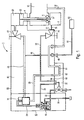
- the valve arrangement 1 according to FIG. 1 is for securing the pressure of a pressure vessel 2 provided.
- the pressure vessel 2 can in particular the pressure vessel a nuclear plant or a nuclear power plant.
- the valve assembly 1 includes a safety valve to secure the pressure vessel 2 4.
- the safety valve 4 comprises a valve cone 6, which in the normal state Blow-off opening 8 of the pressure vessel closes tightly. However, if the pressure in the Pressure vessel 2 exceeds a predefinable setpoint, the safety valve opens 4, the valve cone 6 opening the blow-off opening 8. This will make the interior of the pressure vessel 2 connected to a blow-off line 10, via the When the safety valve is open 4 gas, water and / or steam from the interior of the pressure vessel 2 to a downstream collecting device or in the environment can be drained. If the pressure in the pressure tank 2 safety valve 4, on the other hand, closes again, so that the interior of the pressure vessel 2 again on the pressure side is decoupled from the blow-off line 10.
- the safety valve 4 is a control valve in the manner of a control device 12 assigned.
- the control valve 12 is in turn designed in two stages and includes a main control module 14 and an upstream pilot module 16th
- the valve arrangement 1 is designed according to the relief principle. To do this includes the safety valve 4 has a control chamber 20 which, in the normal operating state is subjected to a working pressure. Due to this working pressure, a in the control chamber 20 guided piston 22 of the valve cone 6 securely in its blow-off opening 8 of the pressure vessel 2 closing valve seat held. in the Relief occurs, a relief or a pressure reduction in the control room 20, see above that the pressure prevailing in the pressure vessel 2 pushes the valve cone 6 out of its seat moves and thus releases the relief opening.
- the need-based relief of the control room 20 for targeted control of the safety valve 4 takes place via a first media line 24, via which the Control room 20 is connected to the main control module 14. Opens in response the main control module 14 connects the first media line 24 to a second media line 26, which is connected on the outlet side to the blow-off channel 10 is. Provide the first media line 24 and the second media line 26 thus in its entirety a relief line that can be released by the main control module 14 for the control room 20 of the safety valve 4.
- the main control module 14 is itself also media-controlled and in addition connected to the pilot module 16 via a third media line 28.
- pilot module 16 provides a connection to the third media line 28 with a guided media line 30 free, the output side in not shown Way is also connected to a blow-off channel.
- the third media line 28 and the fourth media line 30 that can be connected to this position in its entirety also represents a relief line through which the main control module 14 can be relieved on the pressure side. As a result of such Pressure relief of the main control module 14 switches the first media line 24 to relieve pressure in the control chamber 20 of the safety valve 4.
- the pilot control module 16 To trigger a relief of the main control module 14 by producing one Connection between the third media line 28 and the fourth media line 30 is the pilot control module 16 via the pressure prevailing in the pressure vessel 2 driven.
- the pilot control module 16 is designed as a pulse line fifth media line 32 connected to the interior of the pressure vessel 2.
- One of the fifth media line 32 branches off as a fill line for the pilot control module 16 configured sixth media line 34.
- the safety valve 4 and the control valve 12 communicating with it via the media lines 24, 26, 28, 30, 32, 34 are designed in the manner described in DE 196 28 610 C1.
- the media lines 24, 26, 28, 30, 32, 34 are in particular designed as suitable bores or channels.
- the safety valve 4 and the control valve 12 assigned to it are arranged on a common shut-off block 40, on which they are mechanically fixed on the one hand and in which on the other hand the media lines 24, 26, 28, 30, 32, 34 are guided.
- Aids and fittings such as, for example, an externally actuated shut-off valve 42 for the first media line 24 or an externally actuated shut-off valve 44 for the fifth media line 32 are also integrated in the shut-off block 40.
- a branch line 46 branching from the first media line 24 is also guided through the shut-off block 40 and is connected to a pressure sensor 52 via a flange 48 and a line 50. Via the pressure sensor 52, the pressure currently present in the control chamber 20 of the safety valve 4 can also be detected during the operation of the valve arrangement 1.
- the fifth media line 32 emerging from the shut-off block 40 in the area of the shut-off valve 44 is connected to the pressure vessel 2 via a flange 54 connected to the shut-off block 40 and a removal line 56 connected to it.
- the valve arrangement 1 is, in particular due to the design of the safety valve 4 and the control valve 12, also for use over a comparatively suitable for a long period of time in a core Kratttechnik facility.
- the valve arrangement 1 is used, it is provided in particular continue to be used even after a number of fuel element cycles.
- Around but always ensuring the greatest possible plant safety is during a regular fuel element change is not a complete one Replacement of the valve arrangement 1, but at least a complete function check the valve assembly 1 provided.
- the valve assembly 1 is therefore designed to perform such a function check when installed to enable with comparatively little effort.
- the shut-off block 40 in which the safety valve 4 and the control valve 12 media lines 24 connecting one another and with the outside world, 26, 28, 30, 32, 34 are performed in two parts and includes one as the actual Carrier block provided main block 60 and a detachable with this connected adapter block 62.
- the main block 60 is comparatively solid executed and also serves as a support block for the control valve 12.
- Der Adapter block 62 is comparative to main block 60 small size and includes a number of media side Interconnection of the media lines 24, 26, 28, 30, 32, 34 determining control channels 64th
- the adapter block 62 is an operating adapter or operating flange, the control channels guided in it 64 for setting a medium-side operating configuration for the valve arrangement 1 are designed. This is in particular the second medium line 26 held continuously over one of the control channels 64. Likewise, one of the Control channels 64 held the fifth media line 32 continuously.
- the media lines 24, 26, 28, 30, 32, 34 open into the main block 60 at interfaces 66 determined according to a predefinable standard to adapter block 62.
- test configuration in a shown in the embodiment of FIG. 2 The test configuration is carried out in that for setting the operating configuration designed adapter block 62 is replaced by one for setting the Test configuration designed further adapter block 70.
- This thus serves as Test adapter or test flange.
- For the functional test of the valve arrangement 1 is namely provided a targeted in the depressurized state of the pressure vessel 2 Actuation of individual active components of the valve arrangement 1, for example the pilot control module 16 or the main control module 14 with test pressures under test conditions.
- the additional adapter block 70 for one on these test conditions coordinated media connection of media lines 24, 26, 28, 30, 32, 34 designed.
- the further adapter block 70 has control channels 72, which are connected to the now desired media-side interconnection are adapted.
- the second media line 26 and the fifth media line 32 are not continuous led, but made accessible with two half parts separately.
- the control channels 72 which are suitably connected to the second media line 26 and are connected to the fifth media line 32, essentially passed straight through the additional adapter block 70.
- the control channels 72 ends on the output side in test flanges 74, to which one for carrying out the Suitable test device can be connected.
- valve arrangement 1 there is a switchover between the operating configuration and test configuration in a particularly simple manner simply by an exchange allows the adapter blocks 62, 70 against each other.
- the switchover can thus be carried out with particularly little operating effort, in particular also connection errors during the switchover - for example when comparative complex, media-based interconnection - safely avoided.
- the adjustment test of the control valve 12 can be carried out.
- the safety valve 4 is also designed according to the relief principle.
- the concept of the valve arrangement 1 is also suitable for an after Load principle executed safety valve, in which case the the additional adapter block 70 designed as a test flange also performs the motion test of the safety valve can be carried out in a particularly simple manner.
Landscapes
- Engineering & Computer Science (AREA)
- General Engineering & Computer Science (AREA)
- Physics & Mathematics (AREA)
- Mechanical Engineering (AREA)
- High Energy & Nuclear Physics (AREA)
- Fluid Mechanics (AREA)
- Plasma & Fusion (AREA)
- Valve Housings (AREA)
- Safety Valves (AREA)
- Pipeline Systems (AREA)
- Feeding And Controlling Fuel (AREA)
- Magnetically Actuated Valves (AREA)
- Lift Valve (AREA)
Abstract
Description
Die Erfindung betrifft eine Ventilanordnung mit einem Absperrblock, an dem ein Sicherheitsventil und ein mit diesem über eine Anzahl von im Absperrblock geführten Medienleitungen kommunizierendes Steuerventil angeordnet sind.The invention relates to a valve arrangement with a shut-off block on which a Safety valve and one with this over a number of led in the shut-off block Media lines communicating control valve are arranged.
Druckführende Komponenten oder Aggregate technischer Anlagen, wie beispielsweise der Druckbehälter einer kerntechnischen Anlage, sind üblicherweise durch Sicherheitsventile gegen das Auftreten auslegungsüberschreitender Überdrücke in ihrem Innenraum abgesichert. Dazu ist beispielsweise dem Druckbehälter einer kerntechnischen Anlage üblicherweise eine Anzahl von Sicherheitsventilen zugeordnet, die bei Überschreiten eines vorgebbaren Grenzdrucks im Druckbehälter einen Abblaseweg freigeben. Über den Abblaseweg erfolgt im Bedarfsfall eine Entspannung des Druckbehälters bis zu einem Druckniveau unterhalb eines als zulässig erachteten Grenzdrucks. Gerade beim Einsatz derartiger Sicherheitsventile in kerntechnischen Anlagen ist aufgrund der dort herrschenden Anforderungen an betriebliche Sicherheit und Sorgfalt die Einhaltung vergleichsweise strenger Vorschriften hinsichtlich Zuverlässigkeit und Reproduzierbarkeit des Schließverhaltens auch der Sicherheitsventile erforderlich.Pressure-carrying components or units of technical systems, such as the pressure vessel of a nuclear facility are common by means of safety valves against the occurrence of excess design pressures secured in their interior. For example, the pressure vessel a nuclear plant usually has a number of safety valves assigned, which when a predetermined limit pressure in the Release the pressure vessel through a blow-off path. If necessary, via the blow-off path relaxation of the pressure vessel to a pressure level below a limit pressure which is considered admissible. Especially when using such Safety valves in nuclear plants is due to the prevailing there Comparatively, requirements for operational safety and care compliance strict regulations regarding reliability and reproducibility the closing behavior of the safety valves is also required.
Zur zuverlässigen Einhaltung auch vergleichsweise strenger Vorgaben kann ein derartiges Sicherheitsventil mit einem Steuerventil gekoppelt sein, das seinerseits wiederum ein Hauptsteuermodul und ein Vorsteuermodul umfassen kann. Durch eine geeignete Verschaltung dieser Module oder Komponenten kann sichergestellt werden, daß das Sicherheitsventil hinsichtlich seiner Schaltcharakteristik und seiner Schaltschwellen im Hinblick auf den vorgesehenen Anwendungszweck vorgebbare Bedingungen erfüllt.To reliably comply with comparatively strict requirements, a such a safety valve can be coupled to a control valve, which in turn can in turn comprise a main control module and a pilot control module. By a suitable interconnection of these modules or components can be ensured be that the safety valve in terms of its switching characteristics and its switching thresholds with regard to the intended application predeterminable conditions met.
Aus der DE 196 28 610 C1 ist eine Ventilanordnung bekannt, die insbesondere für den Einsatz in einem Kernkraftwerk geeignet ist. Diese Ventilanordnung umfaßt ein Sicherheitsventil sowie eine ein Vor- und ein Hauptsteuermodul aufweisende Steuereinheit, auch als Steuerventil bezeichnet. Sowohl das Sicherheitsventil als auch das Steuerventil der bekannten Ventilanordnung sind nach dem sogenannten Entlastungsprinzip ausgestaltet, wobei der geschlossene Zustand des Sicherheitsventils und auch des Steuerventils durch eine geeignete Beaufschlagung mit hohem Druck aus einem druckführenden System aufrecht erhalten wird. Falls bei dieser Ventilanordnung der Anpreßdruck des Steuerventils überschritten wird, so erfolgt über einen Druck-Weg-Umformer die Öffnung eines Abblasesystems im Steuerventil, was zu einer Entlastung eines Steuerraums des Steuerventils führt. Infolge dieser Entlastung weicht ein Ventilkegel des Steuerventils aus seinem Ventilsitz und gibt dabei eine mit einem Steuerraum des eigentlichen Sicherheitsventils verbundene Entlastungsleitung frei. Über diese wird anschließend der Steuerraum des eigentlichen Sicherheitsventils entlastet. Aufgrund dieser Entlastung wird der Ventilkegel des Sicherheitsventils aus seinem Ventilsitz bewegt und gibt damit eine mit dem abzusichernden Druckgefäß verbundene Ablaßleitung frei.A valve arrangement is known from DE 196 28 610 C1, which is particularly suitable for is suitable for use in a nuclear power plant. This valve assembly includes a safety valve and a pilot and a main control module Control unit, also known as a control valve. Both the safety valve and the control valve of the known valve arrangement are according to the so-called Relief principle designed, the closed state of the safety valve and also the control valve with a suitable application high pressure is maintained from a pressurized system. If at this valve arrangement the contact pressure of the control valve is exceeded, so a blow-off system is opened via a pressure-displacement converter Control valve, which leads to relief of a control chamber of the control valve. As a result of this relief, a valve cone of the control valve moves out of its Valve seat and there is one with a control room of the actual safety valve connected discharge line free. This is then the Control room of the actual safety valve is relieved. Because of this relief the valve plug of the safety valve is moved out of its valve seat and thus releases a drain line connected to the pressure vessel to be protected.
Eine derartige Ventilanordnung kann einen sogenannten Absperrblock umfassen, an dem das Sicherheitsventil und das Steuerventil montiert sind. In diesem Absperrblock sind üblicherweise die Medienleitungen geführt, über die das Sicherheitsventil mit dem Steuerventil kommuniziert. Diese Medienleitungen umfassen dabei die genannten Entlastungsleitungen, über die die Steuerräume des Steuerventils und des Sicherheitsventils druckentlastet werden, sowie Impulsleitungen zur Weiterleitung des Druckes aus dem abzusichernden Druckgefäß und/oder Auffüllleitungen, über die die Steuerräume nach erfolgter Betätigung des jeweiligen Ventils wieder mit druckführendem Medium beaufschlagbar sind.Such a valve arrangement can comprise a so-called shut-off block, on which the safety valve and the control valve are mounted. In this block are usually the media lines through which the safety valve communicates with the control valve. These include media lines the relief lines mentioned, via which the control rooms of the control valve and the safety valve are relieved of pressure, as well as impulse lines for forwarding the pressure from the pressure vessel to be protected and / or Filling lines through which the control rooms after actuation of the respective Valve can be pressurized again.
Derartige Ventilanordnungen zählen üblicherweise zu den sicherheitsrelevanten Bauteilen in einer kerntechnischen Anlage. Aus diesem Grund und wegen der beim Einsatz in einer kerntechnischen Anlage zu beachtenden strengen Sicherheitsvorkehrungen werden derartige Ventilanordnungen bei einem Einsatz in einer kerntechnischen Anlage üblicherweise vielfältigen Funktionsprüfungen unterzogen. Dabei ist üblicherweise nach dem Einbau einer derartigen Ventilanordnung zunächst eine sogenannte Einstellprüfung vorgesehen, bei der die Grundeinstellungen der jeweiligen Ventilanordnung wie beispielsweise der Ansprechdruck, Federkräfte oder Federwege im Hinblick auf die existierenden Vorgaben oder im Hinblick auf die speziellen Anforderungen jeweiligen Anlage feinjustiert werden. Darüber hinaus können Funktionsprüfungen sämtlicher individuellen Komponenten der Ventilanordnung sowie wiederkehrende Prüfungen der Ventilanordnung im Hinblick auf Einzelsituationen vorgesehen sein. Die Einstellprüfung ist dabei die Hauptprüfung der jeweiligen Ventilanordnung, die bei deren Einbau vorgenommen wird.Such valve arrangements are usually safety-relevant Components in a nuclear facility. Because of this and because of the Strict safety precautions to be observed when used in a nuclear facility are such valve arrangements when used in a nuclear plant usually subjected to a variety of functional tests. This is usually after the installation of such a valve arrangement Initially, a so-called adjustment test is provided, in which the basic settings the respective valve arrangement such as the response pressure, spring forces or travel with regard to the existing requirements or in With regard to the special requirements of each system. In addition, functional tests of all individual components can be carried out the valve arrangement as well as recurrent tests of the valve arrangement in the With regard to individual situations. The setting test is the Main inspection of the respective valve arrangement, which was carried out during their installation becomes.
In bestehenden Kernkraftwerksanlagen ist üblicherweise im Zyklus von etwa einem Jahr der Austausch von Brennelementen vorgesehen. Aufgrund von Erfahrungen, daß die zur Absicherung des Druckbehälters verwendeten Ventilanordnungen in etwa diesem Zeitraum auch zur Leckagebildung neigen, ist üblicherweise gemeinsam mit dem Austausch von Brennelementen, der ohnehin einen vorübergehenden Stillstand des jeweiligen Kernkraftwerks bedingt, ein paralleler standardmäßiger Austausch von Ventilanordnungen vorgesehen. Die dabei neu installierten Ventilanordnungen werden üblicherweise vor oder bei ihrer Inbetriebnahme den genannten Funktionsprüfungen, insbesondere der Einstellprüfung, unterzogen.In existing nuclear power plants, there is usually a cycle of about one Year of replacement of fuel assemblies provided. Based on experience, that the valve assemblies used to secure the pressure vessel tend to form a leak in about this period is common together with the replacement of fuel elements, which is already a temporary one A shutdown of the respective nuclear power plant requires a parallel one Standard replacement of valve arrangements provided. The new one Installed valve assemblies are usually installed before or during commissioning the functional tests mentioned, in particular the adjustment test, subjected.
Bei der Entwicklung neuerer und hochkomplexer Ventilanordnungen ist es jedoch gelungen, deren insgesamt verfügbare Einsatzdauer und insbesondere den Zeitraum bis zum Auftreten möglicher Leckagen deutlich auch über den bisher veranschlagten Einsatzzeitraum von etwa einem Jahr hinaus zu steigern. Daher ist nunmehr der Einsatz derartiger Ventilanordnungen auch über mehrere Brennelement-Zyklen hinweg denkbar. Um hierbei jedoch möglicherweise sicherheitsrelevante Fehlfunktionen der Ventilanordnung sicher auszuschließen, ist auch in diesem Fall bei jedem Brennelement-Wechsel in einer Kernkraftwerksanlage eine vollständige Funktionsüberprüfung der Ventilanordnungen vorgesehen, selbst wenn diese nicht unmittelbar auszutauschen sind. Derartige Prüfungen erfolgen üblicherweise mittels eines dafür vorgesehenen Prüfgeräts, mit dem einzelne Komponenten der Ventilanordnung im an sich drucklosen Zustand des abzusichernden Druckbehälters gezielt mit einem Prüfdruck beaufschlagt werden. Derartige Prüfungen sind insbesondere aufgrund einer Vielzahl dazu vorzunehmender Verschaltungsänderungen und im Hinblick auf die Handhabung zahlreicher dafür benötigter Komponenten vergleichsweise aufwendig.However, when developing newer and more complex valve assemblies, it is succeeded, their total available duration and in particular the period until the occurrence of possible leaks, well above the previously estimated Increase deployment period of about a year. thats why now the use of such valve arrangements also over several fuel element cycles conceivable away. In order to do this, however, may be security-relevant It is also safe to rule out malfunctions in the valve arrangement One case for every fuel element change in a nuclear power plant full functional check of the valve arrangements provided, even if these cannot be exchanged immediately. Such tests are carried out usually using a test device provided for this purpose, with which the individual Components of the valve arrangement in the pressure-free state of the item to be secured Pressure container can be specifically subjected to a test pressure. such Examinations are particularly to be taken due to a large number of them Circuit changes and numerous in terms of handling components required for this are comparatively complex.
Der Erfindung liegt daher die Aufgabe zugrunde, eine Ventilanordnung der oben genannten Art anzugeben, bei der der Handhabungs- oder Bedienungsaufwand für die Durchführung der genannten Funktionsprüfungen besonders gering gehalten ist.The invention is therefore based on the object, a valve arrangement of the above Specify the type mentioned, in which the handling or operating effort kept particularly low for carrying out the functional tests mentioned is.
Diese Aufgabe wird erfindungsgemäß gelöst, indem der Absperrblock einen Hauptblock und einen mit diesem lösbar verbundenen Adapterblock umfaßt, der eine Anzahl von die medienseitige Verschaltung der Medienleitungen bestimmenden Steuerkanälen aufweist.This object is achieved in that the shut-off block one Main block and an adapter block releasably connected to this, the a number of determining the media-side interconnection of the media lines Control channels has.
Die Erfindung geht dabei von der Überlegung aus, daß der Aufwand bei der Prüfung der Ventilanordnung besonders gering gehalten werden kann, indem diese in eingebautem Zustand und mit nur geringfügigen Handgriffen von ihrer Betriebskonfiguration in ihre Prüfkonfiguration und umgekehrt umgeschaltet werden kann. Die Betriebskonfiguration und die Prüfkonfiguration unterscheiden sich jedoch üblicherweise lediglich in der Art der Verschaltung der das Steuerventil und das Sicherheitsventil miteinander und mit ihrer Außenwelt verbindenden Medienleitungen. Eine geeignete Umschaltung zwischen Betriebskonfiguration und Prüfkonfiguration ist daher erreichbar, indem auf besonders einfache Weise die Verschaltung der Medienleitungen veränderbar gehalten ist. Dazu ist der Absperrblock in einen Hauptblock und in einen Adapterblock unterteilt, wobei der Hauptblock sowohl zur Befestigung von Steuerventil und Sicherheitsventil dient als auch die wesentlichen Teile der Medienleitungen führt. Im Adapterblock sind hingegen Steuerkanäle derart geführt, daß durch geeignete Kombination mit den im Hauptblock vorgesehenen Medienleitungen die jeweils gewünschte Verschaltung entsteht. The invention is based on the consideration that the effort involved in testing the valve arrangement can be kept particularly low by this in installed condition and with only minor manipulations of your operating configuration can be switched to their test configuration and vice versa. However, the operational configuration and the test configuration usually differ only in the type of connection of the control valve and the safety valve media lines connecting each other and their outside world. A suitable switchover between operational configuration and test configuration can therefore be achieved by connecting the circuit in a particularly simple manner the media lines are kept changeable. The shut-off block is in a main block and divided into an adapter block, the main block being both to attach the control valve and safety valve serves as the essential Parts of the media lines leads. Control channels are in the adapter block led such that by a suitable combination with those in the main block provided media lines, the desired interconnection is created.
Um dabei mit besonders geringem Aufwand und auf besonders einfache Weise eine Vielzahl von Schaltungsvarianten verfügbar zu machen, münden die Medienleitungen in vorteilhafter Ausgestaltung im Hauptblock an nach einem vorgebbaren Standard ermittelten Positionen in die Grenzfläche zum Adapterblock. Somit kann eine Vielzahl von Adapterblöcken, die aufgrund geeigneter Führung der in sie integrierten Steuerkanäle jeweils eine andere Verschaltung der Medienleitungen vorgeben, ohne weiteren Aufwand mit dem Hauptblock kombiniert werden, da diese lediglich der Randbedingung unterliegen, daß an den durch den Standard vorgegebenen Positionen in ihrer Grenzfläche zum Hauptblock die entsprechenden Steuerkanäle enden müssen.To do so with particularly little effort and in a particularly simple manner The media lines lead to making a large number of circuit variants available in an advantageous embodiment in the main block according to a predefinable Standard determined positions in the interface to the adapter block. Consequently can be a variety of adapter blocks, which due to appropriate guidance of the control channels integrated in it each have a different interconnection of the media lines specify to be combined with the main block without further effort, since these are only subject to the constraint that the standard given positions in their interface to the main block the corresponding Control channels must end.
Vorteilhafterweise ist der Hauptblock alternativ mit einem einer Betriebskonfiguration der Medienleitungen entsprechenden Adapterblock oder mit einem einer Prüfkonfiguration der Medienleitungen entsprechenden Adapterblock kombinierbar. Bei einer derartigen Ventilanordnung kann somit durch einfachen Austausch des Adapterblocks ohne weitere Maßnahmen zwischen einer Betriebskonfiguration der Ventilanordnung und einer Prüfkonfiguration der Ventilanordnung umgeschaltet werden.The main block is alternatively advantageously with an operating configuration the adapter block corresponding to the media lines or with a one Test configuration of the media lines can be combined with the corresponding adapter block. With such a valve arrangement, it can thus be replaced by simple replacement the adapter block without further measures between an operational configuration of the valve arrangement and a test configuration of the valve arrangement become.
Vorteilhafterweise ist das Sicherheitsventil der Ventilanordnung nach dem Entlastungsprinzip oder nach dem Belastungsprinzip ausgeführt.The safety valve of the valve arrangement is advantageously based on the relief principle or carried out according to the load principle.
Um auch während des Betriebs der Ventilanordnung in der Art einer online-Erfassung eine andauernde Überprüfung des Druckzustands in einem Steuerraum des oder jeden Ventils zu ermöglichen, kommuniziert in weiterer vorteilhafter Ausgestaltung zumindest eine der im Absperrblock geführten Medienleitungen medienseitig mit einem Drucksensor.To even during the operation of the valve assembly in the manner of an online capture an ongoing check of the pressure condition in a control room To enable the or each valve communicates in a further advantageous embodiment at least one of the media lines in the shut-off block on the media side with a pressure sensor.
Die mit der Erfindung erzielten Vorteile bestehen insbesondere darin, daß durch die Unterteilung des zwischen das Sicherheitsventil und das Steuerventil geschalteten Absperrblocks in einen Hauptblock und in einen Adapterblock auf besonders einfache Weise eine Umschaltung der Ventilanordnung zwischen verschiedenen Schaltzuständen der Medienleitungen ermöglicht ist. Durch den Hauptblock, an dem das Sicherheitsventil und das Steuerventil montiert sind, können die Medienleitungen dabei in ihrem wesentlichen Verlauf fest vorgegeben sein. Die Anordnung aus Sicherheitsventil, Steuerventil und dem dazwischen geschalteten Hauptblock kann somit auch bei Umschaltung der medienseitigen Verschaltung fest installiert bleiben.The advantages achieved by the invention are in particular that the division of the between the safety valve and the control valve Barrier blocks in a main block and an adapter block on special simple switching of the valve arrangement between different Switching states of the media lines is enabled. By the Main block on which the safety valve and the control valve are mounted the media lines are predefined in their essential course his. The arrangement of the safety valve, control valve and the intermediary The main block can also be used when switching the media-side interconnection remain permanently installed.
Eine Umschaltung zwischen verschiedenen Schaltzuständen der Ventilanordnung kann dabei durch einfachen Austausch des Adapterblocks erfolgen, wobei die medienseitige Verschaltung der Medienleitungen durch die bedarfsangepaßt im jeweiligen Adapterblock geführten Steuerkanäle erfolgt. Der Adapterblock stellt somit in der Art eines "festverdrahteten Bauteils" sicher, daß durch den Austausch lediglich eines Bauteils eine Umschaltung auch zwischen vergleichsweise komplexen Schaltzuständen ohne weiteres erfolgen kann, wobei insbesondere bei vergleichsweise komplexen medienseitigen Schaltungen Schaltfehler sicher vermieden sind, zumal eine individuelle Leitungsinstallation gerade nicht erforderlich ist. Dadurch ist eine situationsangepaßte Umschaltung zwischen Prüfungskonfiguration und Betriebskonfiguration der Ventilanordnung jederzeit mit nur geringem Aufwand möglich. Somit ist der Aufwand bei der Prüfung einer derartigen Ventilanordnung besonders gering gehalten, wodurch insbesondere die Weiterverwendung einer derartigen Ventilanordnung über mehrere Betriebszyklen hinweg besonders erleichtert ist.Switching between different switching states of the valve arrangement can be done by simply replacing the adapter block, the Media-side interconnection of the media lines through the customized in control block guided adapter block takes place. The adapter block provides thus in the manner of a "hard-wired component" sure that by the exchange switching of only one component also between comparatively complex ones Switching states can be done easily, especially in comparison complex media-side circuits reliably avoid switching errors are, especially since an individual line installation is not required. This is a situation-specific switch between test configuration and operating configuration of the valve arrangement at any time with little effort possible. Thus, the effort involved in testing such a valve arrangement kept particularly low, which in particular further use of such a valve arrangement particularly over several operating cycles is relieved.
Ein Ausführungsbeispiel der Erfindung wird anhand einer Zeichnung näher erläutert. Darin zeigen:
- Fig. 1
- eine Ventilanordnung in einer ersten Schaltungskonfiguration, und
- Fig. 2
- die Ventilanordnung nach Fig. 1 in einer zweiten Schaltungsanordnung.
- Fig. 1
- a valve arrangement in a first circuit configuration, and
- Fig. 2
- 1 in a second circuit arrangement.
Gleiche Teile sind in beiden Figuren mit den selben Bezugszeichen versehen. Identical parts are provided with the same reference symbols in both figures.
Die Ventilanordnung 1 nach Fig. 1 ist zur Druckabsicherung eines Druckbehälters
2 vorgesehen. Der Druckbehälter 2 kann dabei insbesondere der Druckbehälter
einer kerntechnischen Anlage oder einer Kernkraftwerksanlage sein. Die Ventilanordnung
1 umfaßt zur Absicherung des Druckbehälters 2 ein Sicherheitsventil
4. Das Sicherheitsventil 4 umfaßt einen Ventilkegel 6, der im Normalzustand eine
Abblaseöffnung 8 des Druckbehälters dicht verschließt. Falls jedoch der Druck im
Druckbehälter 2 einen vorgebbaren Sollwert übersteigt, öffnet das Sicherheitsventil
4, wobei der Ventilkegel 6 die Abblaseöffnung 8 freigibt. Dadurch wird der Innenraum
des Druckbehälters 2 mit einer Abblaseleitung 10 verbunden, über die
bei geöffnetem Sicherheitsventil 4 Gas, Wasser und/oder Dampf aus dem Innenraum
des Druckbehälters 2 an eine nachgeschaltete Auffangeinrichtung oder in
die Umgebung abgelassen werden kann. Wenn der Druck im Druckbehälter 2
unter den vorgebbaren Sollwert gefallen ist, schließt das Sicherheitsventil 4 hingegen
wieder, so daß der Innenraum des Druckbehälters 2 wiederum druckseitig
von der Abblaseleitung 10 entkoppelt ist.The
Zur Steuerung des Sicherheitsventils 4 in Abhängigkeit vom Druck im Druckbehälter
2 ist dem Sicherheitsventil 4 in der Art einer Steuereinrichtung ein Steuerventil
12 zugeordnet. Das Steuerventil 12 ist seinerseits zweistufig ausgebildet
und umfaßt ein Hauptsteuermodul 14 und ein dem vorgeschaltetes Vorsteuermodul
16.To control the
Die Ventilanordnung 1 ist nach dem Entlastungsprinzip ausgeführt. Dazu umfaßt
das Sicherheitsventil 4 einen Steuerraum 20, der im normalen Betriebszustand mit
einem Arbeitsdruck beaufschlagt ist. Durch diesen Arbeitsdruck wird mittels eines
im Steuerraum 20 geführten Kolbens 22 der Ventilkegel 6 sicher in seinen die Abblaseöffnung
8 des Druckbehälters 2 verschließenden Ventilsitz gehalten. Im
Auslösefall erfolgt eine Entlastung oder ein Druckabbau im Steuerraum 20, so
daß der im Druckbehälter 2 herrschende Druck den Ventilkegel 6 aus seinem Sitz
bewegt und somit die Entlastungsöffnung freigibt. The
Die bedarfsgerechte Entlastung des Steuerraums 20 zur gezielten Ansteuerung
des Sicherheitsventils 4 erfolgt über eine erste Medienleitung 24, über die der
Steuerraum 20 mit dem Hauptsteuermodul 14 verbunden ist. Im Ansprechfall öffnet
das Hauptsteuermodul 14 eine Verbindung der ersten Medienleitung 24 mit
einer zweiten Medienleitung 26, die ausgangsseitig mit dem Abblasekanal 10 verbunden
ist. Die erste Medienleitung 24 und die zweite Medienleitung 26 stellen
somit in ihrer Gesamtheit eine durch das Hauptsteuermodul 14 freigebbare Entlastungsleitung
für den Steuerraum 20 des Sicherheitsventils 4 dar.The need-based relief of the
Das Hauptsteuermodul 14 ist seinerseits ebenfalls mediengesteuert und dazu
über eine dritte Medienleitung 28 mit dem Vorsteuermodul 16 verbunden. Das
Vorsteuermodul 16 gibt im Auslösefall eine Verbindung der dritten Medienleitung
28 mit einer geführter Medienleitung 30 frei, die ausgangsseitig in nicht näher dargestellter
Weise ebenfalls mit einem Abblasekanal verbunden ist. Die dritte Medienleitung
28 und die mit dieser verbindbare vierte Medienleitung 30 stellen somit
in ihrer Gesamtheit ebenfalls eine Entlastungsleitung dar, über die das Hauptsteuermodul
14 druckseitig entlastet werden kann. Infolge einer derartigen
Druckentlastung des Hauptsteuermoduls 14 schaltet dieses die erste Medienleitung
24 zur Druckentlastung des Steuerraums 20 des Sicherheitsventils 4 durch.The
Zur Auslösung einer Entlastung des Hauptsteuermoduls 14 durch Herstellen einer
Verbindung zwischen der dritten Medienleitung 28 und der vierter Medienleitung
30 ist das Vorsteuermodul 16 über den im Druckbehälter 2 herrschenden Druck
angesteuert. Dazu ist das Vorsteuermodul 16 über eine als Impulsleitung ausgebildete
fünfte Medienleitung 32 mit dem Innenraum des Druckbehälters 2 verbunden.
Von der fünften Medienleitung 32 zweigt eine als Auffüllleitung für das Vorsteuermodul
16 ausgestaltete sechste Medienleitung 34 ab.To trigger a relief of the
Hinsichtlich ihrer Wirkungs- und Arbeitsweise sowie insbesondere hinsichtlich ihres
medienseitigen Zusammenwirkens sind das Sicherheitsventil 4 und das mit
diesem über die Medienleitungen 24, 26, 28, 30, 32, 34 kommunizierende Steuerventil
12 in der in der DE 196 28 610 C1 beschriebenen Bauweise ausgeführt. Die
Medienleitungen 24, 26, 28, 30, 32, 34 sind dabei insbesondere als geeignete
Bohrungen oder Kanäle ausgeführt. Zur weiteren Erläuterung der Funktionsweise
des Sicherheitsventils 4 und des diesem zugeordneten Steuerventils 12 wird auf
diese Beschreibung in vollem Umfang verwiesen.
Das Sicherheitsventil 4 und das diesem zugeordnete Steuerventil 12 sind an einem
gemeinsamen Absperrblock 40 angeordnet, an dem sie einerseits mechanisch
fixiert sind, und in dem andererseits die Medienleitungen 24, 26, 28, 30, 32,
34 geführt sind. In den Absperrblock 40 sind zudem auch Hilfsmittel und Armaturen
wie beispielsweise ein von außen betätigbares Absperrventil 42 für die erste
Medienleitung 24 oder ein von außen betätigbares Absperrventil 44 für die fünfte
Medienleitung 32 integriert. Weiterhin ist durch den Absperrblock 40 auch eine
von der ersten Medienleitung 24 abzweigende Stichleitung 46 geführt, die über
einen Flansch 48 und eine Leitung 50 mit einem Drucksensor 52 verbunden ist.
Über den Drucksensor 52 ist dabei auch während des Betriebs der Ventilanordnung
1 der im Steuerraum 20 des Sicherheitsventils 4 aktuell anliegende Druck
erfaßbar. Die im Bereich des Absperrventils 44 aus dem Absperrblock 40 austretende
fünfte Medienleitung 32 ist über einen mit dem Absperrblock 40 verbundenen
Flansch 54 und eine daran angeschlossene Entnahmeleitung 56 mit dem
Druckbehälter 2 verbunden.With regard to their mode of operation and operation, and in particular with regard to their interaction on the media side, the
The
Die Ventilanordnung 1 ist, insbesondere aufgrund der Ausgestaltung des Sicherheitsventils
4 und des Steuerventils 12, auch für einen Einsatz über einen vergleichsweise
langen Zeitraum hinweg in einer Kernkrattwerksanlage geeignet.
Beim Einsatz der Ventilanordnung 1 ist dabei insbesondere vorgesehen, diese
auch über eine Anzahl von Brennelement-Zyklen hinaus weiter zu verwenden. Um
aber dabei stets die größtmögliche Anlagensicherheit zu gewährleisten, ist während
eines turnusgemäßen Brennelementwechsels zwar nicht ein vollständiger
Austausch der Ventilanordnung 1, aber zumindest doch eine vollständige Funktionsüberprüfung
der Ventilanordnung 1 vorgesehen. Die Ventilanordnung 1 ist daher
dafür ausgelegt, eine derartige Funktionsüberprüfung im eingebauten Zustand
mit vergleichsweise geringem Aufwand zu ermöglichen. The
Dazu ist der Absperrblock 40, in dem die das Sicherheitsventil 4 und das Steuerventil
12 miteinander und mit der Außenwelt verbindenden Medienleitungen 24,
26, 28, 30, 32, 34 geführt sind, zweigeteilt ausgeführt und umfaßt einen als eigentlichen
Trägerblock vorgesehenen Hauptblock 60 und einem mit diesem lösbar
verbundenen Adapterblock 62. Der Hauptblock 60 ist dabei vergleichsweise massiv
ausgeführt und dient ebenfalls als Trägerblock für das Steuerventil 12. Der
Adapterblock 62 hingegen ist im Vergleich zum Hauptblock 60 vergleichsweise
gering dimensioniert ausgeführt und umfaßt eine Anzahl von die medienseitige
Verschaltung der Medienleitungen 24, 26, 28, 30, 32, 34 bestimmenden Steuerkanälen
64.For this purpose, the shut-
Im Ausführungsbeispiel gemäß Fig. 1 ist der Adapterblock 62 dabei als Betriebsadapter
oder Betriebsflansch ausgeführt, wobei die in ihm geführten Steuerkanäle
64 zur Einstellung einer mediumseitigen Betriebskonfiguration für die Ventilanordnung
1 ausgelegt sind. Dazu ist insbesondere die zweite Mediumleitung 26
über einen der Steuerkanäle 64 durchgängig gehalten. Ebenso ist durch einen der
Steuerkanäle 64 die fünfte Medienleitung 32 durchgängig gehalten. Um auf besonders
einfache Weise eine medienseitige Umschaltung der Medienleitungen 24,
26, 28, 30, 32, 34 von der Betriebskonfiguration in eine Prüfkonfiguration zu ermöglichen,
münden die Medienleitungen 24, 26, 28, 30, 32, 34 im Hauptblock 60
an nach einem vorgebbaren Standard ermittelten Positionen in die Grenzfläche 66
zum Adapterblock 62.In the exemplary embodiment according to FIG. 1, the
Eine medienseitige Umschaltung der im Ausführungsbeispiel in Fig. 1 dargestellten
Betriebskonfiguration in eine im Ausführungsbeispiel gemäß Fig. 2 dargestellte
Prüfkonfiguration erfolgt dabei, in dem der zur Einstellung der Betriebskonfiguration
ausgelegte Adapterblock 62 ersetzt wird durch einen zur Einstellung der
Prüfkonfiguration ausgelegten weiteren Adapterblock 70. Dieser dient somit als
Prüfadapter oder Prüfflansch. Zur Funktionsprüfung der Ventilanordnung 1 ist
nämlich vorgesehen, im drucklosen Zustand des Druckbehälters 2 eine gezielte
Beaufschlagung einzelner aktiver Komponenten der Ventilanordnung 1 wie beispielsweise
des Vorsteuermoduls 16 oder des Hauptsteuermoduls 14 mit Prüfdrücken
unter Prüfbedingungen vorzunehmen. Um dies auf besonders einfache
Weise zu ermöglichen, ist der weitere Adapterblock 70 für eine auf diese Prüfbedingungen
abgestimmte medienseitige Verschaltung der Medienleitungen 24, 26,
28, 30, 32, 34 ausgelegt.A changeover on the media side of that shown in the exemplary embodiment in FIG. 1
Operating configuration in a shown in the embodiment of FIG. 2
The test configuration is carried out in that for setting the operating configuration
designed
Dazu weist der weitere Adapterblock 70 Steuerkanäle 72 auf, die an die nunmehr
gewünschte medienseitige Verschaltung angepaßt sind. Insbesondere sind dabei
die zweite Medienleitung 26 und die fünfte Medienleitung 32 nicht durchgängig
geführt, sondern mit jeweils zwei Halbteilen getrennt zugänglich gemacht. Dazu
sind die Steuerkanäle 72, die in geeigneter Weise an der zweiten Medienleitung
26 und an der fünften Medienleitung 32 angeschlossen sind, im wesentlichen
gradlinig durch den weiteren Adapterblock 70 hindurchgeführt. Die Steuerkanäle
72 enden ausgangsseitig in Prüfflanschen 74, an die ein zur Durchführung der
Prüfung geeignetes Prüfgerät anschließbar ist.For this purpose, the
Bei der Ventilanordnung 1 ist eine Umschaltung zwischen Betriebskonfiguration
und Prüfkonfiguration auf besonders einfache Weise lediglich durch einen Austausch
der Adapterblöcke 62, 70 gegeneinander ermöglicht. Die Umschaltung
kann somit mit besonders geringem Bedienaufwand erfolgen, wobei insbesondere
auch Verschaltungsfehler bei der Umschaltung - beispielsweise bei vergleichsweise
komplex aufgebauter medienseitiger Verschaltung - sicher vermieden sind.
Durch den Austausch des Adapterblocks 62 gegen den als Prüfflansch oder
Prüfadapter ausgebildeten weiteren Adapterblock 70 ist auf besonders einfache
Weise die Einstellprüfung des Steuerventils 12 durchführbar. Im Ausführungsbeispiel
ist das Sicherheitsventil 4 zudem nach dem Entlastungsprinzip ausgebildet.
Das Konzept nach der Ventilanordnung 1 eignet sich aber auch für ein nach dem
Belastungsprinzip ausgeführtes Sicherheitsventil, wobei in diesem Fall über den
als Prüfflansch ausgebildeten weiteren Adapterblock 70 auch die Bewegungsprüfung
des Sicherheitsventils auf besonders einfache Weise durchführbar ist. In the
Bezugszeichenliste
- 1
- Ventilanordnung
- 2
- Druckbehälter
- 4
- Sicherheitsventil
- 6
- Ventilkegel
- 8
- Abblaseöffnung
- 10
- Abblaseleitung
- 12
- Steuerventil
- 14
- Hauptsteuermodul
- 16
- Vorsteuermodul
- 20
- Steuerraum
- 22
- Kolben
- 24, 26, 28, 30, 32, 34
- Medienleitungen
- 40
- Absperrblock
- 42, 44
- Absperrventile
- 46
- Stichleitung
- 48
- Flansch
- 50
- Leitung
- 52
- Drucksensor
- 54
- Flansch
- 56
- Entnahmeleitung
- 60
- Hauptblock
- 62
- Adapterblock
- 64
- Steuerkanäle
- 66
- Grenzfläche
- 70
- Adapterblock
- 72
- Steuerkanäle
- 74
- Prüfflansche
- 1
- valve assembly
- 2
- pressure vessel
- 4
- safety valve
- 6
- shuttle
- 8th
- blow-off
- 10
- blow-off line
- 12
- control valve
- 14
- Main control module
- 16
- pilot module
- 20
- control room
- 22
- piston
- 24, 26, 28, 30, 32, 34
- media lines
- 40
- Shut-off
- 42, 44
- Shut-off valves
- 46
- stub
- 48
- flange
- 50
- management
- 52
- pressure sensor
- 54
- flange
- 56
- withdrawal line
- 60
- main block
- 62
- adapter block
- 64
- control channels
- 66
- interface
- 70
- adapter block
- 72
- control channels
- 74
- Prüfflansche
Claims (7)
Applications Claiming Priority (4)
| Application Number | Priority Date | Filing Date | Title |
|---|---|---|---|
| DE10129396 | 2001-06-20 | ||
| DE10129396 | 2001-06-20 | ||
| DE10161121 | 2001-12-12 | ||
| DE10161121A DE10161121B4 (en) | 2001-06-20 | 2001-12-12 | valve assembly |
Publications (3)
| Publication Number | Publication Date |
|---|---|
| EP1271027A2 true EP1271027A2 (en) | 2003-01-02 |
| EP1271027A3 EP1271027A3 (en) | 2006-02-15 |
| EP1271027B1 EP1271027B1 (en) | 2008-04-23 |
Family
ID=26009546
Family Applications (1)
| Application Number | Title | Priority Date | Filing Date |
|---|---|---|---|
| EP02012814A Expired - Lifetime EP1271027B1 (en) | 2001-06-20 | 2002-06-10 | Valve device |
Country Status (3)
| Country | Link |
|---|---|
| EP (1) | EP1271027B1 (en) |
| AT (1) | ATE393342T1 (en) |
| DE (1) | DE50212131D1 (en) |
Cited By (1)
| Publication number | Priority date | Publication date | Assignee | Title |
|---|---|---|---|---|
| EP1914460A2 (en) * | 2006-10-18 | 2008-04-23 | AREVA NP GmbH | Method and a device for testing the operability of a valve system |
Citations (1)
| Publication number | Priority date | Publication date | Assignee | Title |
|---|---|---|---|---|
| DE19628610C1 (en) | 1996-07-16 | 1998-01-02 | Siemens Ag | Control device with pressure/displacement converter |
Family Cites Families (3)
| Publication number | Priority date | Publication date | Assignee | Title |
|---|---|---|---|---|
| US4722361A (en) * | 1983-09-22 | 1988-02-02 | Vapor Corporation | Modulating pressure operated pilot relief valve |
| US5842501A (en) * | 1996-08-23 | 1998-12-01 | Flow Safe, Inc. | Pilot operated safety relief valve |
| US6186600B1 (en) * | 1999-06-10 | 2001-02-13 | Westinghouse Air Brake Company | Automatic test connector adapter plate for AB pipe bracket |
-
2002
- 2002-06-10 EP EP02012814A patent/EP1271027B1/en not_active Expired - Lifetime
- 2002-06-10 DE DE50212131T patent/DE50212131D1/en not_active Expired - Lifetime
- 2002-06-10 AT AT02012814T patent/ATE393342T1/en not_active IP Right Cessation
Patent Citations (1)
| Publication number | Priority date | Publication date | Assignee | Title |
|---|---|---|---|---|
| DE19628610C1 (en) | 1996-07-16 | 1998-01-02 | Siemens Ag | Control device with pressure/displacement converter |
Cited By (2)
| Publication number | Priority date | Publication date | Assignee | Title |
|---|---|---|---|---|
| EP1914460A2 (en) * | 2006-10-18 | 2008-04-23 | AREVA NP GmbH | Method and a device for testing the operability of a valve system |
| EP1914460A3 (en) * | 2006-10-18 | 2012-06-13 | AREVA NP GmbH | Method and a device for testing the operability of a valve system |
Also Published As
| Publication number | Publication date |
|---|---|
| ATE393342T1 (en) | 2008-05-15 |
| DE50212131D1 (en) | 2008-06-05 |
| EP1271027B1 (en) | 2008-04-23 |
| EP1271027A3 (en) | 2006-02-15 |
Similar Documents
| Publication | Publication Date | Title |
|---|---|---|
| EP1630425B1 (en) | Safety circuit for a fluid actuated actuator and method for using the same | |
| EP3479008B1 (en) | Tank valve | |
| EP2172656B1 (en) | Hydraulic release unit for a valve unit in a power machine assembly, in particular for a quick-closing valve of a turbine assembly | |
| CH666132A5 (en) | DEVICE FOR MONITORING PHYSICAL QUANTITIES IN PLANTS. | |
| DE102013105910A1 (en) | Electronically controllable and testable turbine quick-closing system and method with redundant discharge manifolds | |
| EP0054602B1 (en) | Own fluid controlled stop valve | |
| EP1757817B1 (en) | Valve arrangement for controlling a quick-acting valve of a gas or vapour turbine | |
| DE2759263A1 (en) | MONITORING SYSTEM FOR HYDRAULICALLY OPERATED FITTINGS | |
| EP1271027A2 (en) | Valve device | |
| DE202011109158U1 (en) | Electrohydraulic safety control | |
| DE102011082599B4 (en) | Valve arrangement, use, turbine and power plant | |
| WO2019122022A1 (en) | Pneumatic control device for multi-zone fire extinguishing systems, and multi-zone fire-extinguishing systems having same | |
| DE10161121B4 (en) | valve assembly | |
| DE102013216790A1 (en) | Switching fitting arrangement | |
| EP1649202B1 (en) | Pressure release device for application in pressurised systems in power stations | |
| DE19532928C2 (en) | Safety valve arrangement for use on pressure maintenance systems in power plants | |
| EP0717201B1 (en) | Protection system in a pressure installation | |
| DE3040367A1 (en) | Safety system for steam or gas turbines - uses combined hydraulic and electrical system with pressure switches and magnetic valves | |
| DE102015210274A1 (en) | Multi-way valve, in particular a 6/2-way valve and multi-way valve arrangement | |
| DE102012105350A1 (en) | Valve for a beverage filling plant, preferably a valve for a filling element of a beverage filling plant | |
| CH660510A5 (en) | PROTECTABLE PROTECTIVE DEVICE FOR STEAM TURBINE PLANTS FOR YOUR FUNCTIONAL SAFETY. | |
| DE3235274A1 (en) | Safety device for control devices such as e.g. pressure reducers | |
| EP0301202B1 (en) | Valve device for fluids under pressure | |
| DE2430765C2 (en) | ||
| EP0870141B1 (en) | Check valve |
Legal Events
| Date | Code | Title | Description |
|---|---|---|---|
| PUAI | Public reference made under article 153(3) epc to a published international application that has entered the european phase |
Free format text: ORIGINAL CODE: 0009012 |
|
| AK | Designated contracting states |
Kind code of ref document: A2 Designated state(s): AT BE CH CY DE DK ES FI FR GB GR IE IT LI LU MC NL PT SE TR |
|
| AX | Request for extension of the european patent |
Free format text: AL;LT;LV;MK;RO;SI |
|
| PUAL | Search report despatched |
Free format text: ORIGINAL CODE: 0009013 |
|
| AK | Designated contracting states |
Kind code of ref document: A3 Designated state(s): AT BE CH CY DE DK ES FI FR GB GR IE IT LI LU MC NL PT SE TR |
|
| AX | Request for extension of the european patent |
Extension state: AL LT LV MK RO SI |
|
| RIC1 | Information provided on ipc code assigned before grant |
Ipc: F16K 17/10 20060101AFI20021004BHEP Ipc: F15B 13/00 20060101ALI20051223BHEP |
|
| 17P | Request for examination filed |
Effective date: 20060804 |
|
| AKX | Designation fees paid |
Designated state(s): AT BE CH CY DE DK ES FI FR GB GR IE IT LI LU MC NL PT SE TR |
|
| GRAP | Despatch of communication of intention to grant a patent |
Free format text: ORIGINAL CODE: EPIDOSNIGR1 |
|
| RAP1 | Party data changed (applicant data changed or rights of an application transferred) |
Owner name: AREVA NP GMBH |
|
| GRAS | Grant fee paid |
Free format text: ORIGINAL CODE: EPIDOSNIGR3 |
|
| GRAA | (expected) grant |
Free format text: ORIGINAL CODE: 0009210 |
|
| AK | Designated contracting states |
Kind code of ref document: B1 Designated state(s): AT BE CH CY DE DK ES FI FR GB GR IE IT LI LU MC NL PT SE TR |
|
| REG | Reference to a national code |
Ref country code: GB Ref legal event code: FG4D Free format text: NOT ENGLISH |
|
| REG | Reference to a national code |
Ref country code: CH Ref legal event code: EP |
|
| REF | Corresponds to: |
Ref document number: 50212131 Country of ref document: DE Date of ref document: 20080605 Kind code of ref document: P |
|
| REG | Reference to a national code |
Ref country code: IE Ref legal event code: FG4D Free format text: LANGUAGE OF EP DOCUMENT: GERMAN |
|
| REG | Reference to a national code |
Ref country code: CH Ref legal event code: NV |
|
| REG | Reference to a national code |
Ref country code: SE Ref legal event code: TRGR |
|
| PG25 | Lapsed in a contracting state [announced via postgrant information from national office to epo] |
Ref country code: ES Free format text: LAPSE BECAUSE OF FAILURE TO SUBMIT A TRANSLATION OF THE DESCRIPTION OR TO PAY THE FEE WITHIN THE PRESCRIBED TIME-LIMIT Effective date: 20080803 Ref country code: PT Free format text: LAPSE BECAUSE OF FAILURE TO SUBMIT A TRANSLATION OF THE DESCRIPTION OR TO PAY THE FEE WITHIN THE PRESCRIBED TIME-LIMIT Effective date: 20080923 |
|
| REG | Reference to a national code |
Ref country code: IE Ref legal event code: FD4D |
|
| BERE | Be: lapsed |
Owner name: AREVA NP G.M.B.H. Effective date: 20080630 |
|
| PG25 | Lapsed in a contracting state [announced via postgrant information from national office to epo] |
Ref country code: IE Free format text: LAPSE BECAUSE OF FAILURE TO SUBMIT A TRANSLATION OF THE DESCRIPTION OR TO PAY THE FEE WITHIN THE PRESCRIBED TIME-LIMIT Effective date: 20080423 Ref country code: MC Free format text: LAPSE BECAUSE OF NON-PAYMENT OF DUE FEES Effective date: 20080630 Ref country code: DK Free format text: LAPSE BECAUSE OF FAILURE TO SUBMIT A TRANSLATION OF THE DESCRIPTION OR TO PAY THE FEE WITHIN THE PRESCRIBED TIME-LIMIT Effective date: 20080423 |
|
| ET | Fr: translation filed | ||
| PLBE | No opposition filed within time limit |
Free format text: ORIGINAL CODE: 0009261 |
|
| STAA | Information on the status of an ep patent application or granted ep patent |
Free format text: STATUS: NO OPPOSITION FILED WITHIN TIME LIMIT |
|
| PG25 | Lapsed in a contracting state [announced via postgrant information from national office to epo] |
Ref country code: BE Free format text: LAPSE BECAUSE OF NON-PAYMENT OF DUE FEES Effective date: 20080630 |
|
| 26N | No opposition filed |
Effective date: 20090126 |
|
| PG25 | Lapsed in a contracting state [announced via postgrant information from national office to epo] |
Ref country code: IT Free format text: LAPSE BECAUSE OF FAILURE TO SUBMIT A TRANSLATION OF THE DESCRIPTION OR TO PAY THE FEE WITHIN THE PRESCRIBED TIME-LIMIT Effective date: 20080423 Ref country code: AT Free format text: LAPSE BECAUSE OF NON-PAYMENT OF DUE FEES Effective date: 20080610 |
|
| PG25 | Lapsed in a contracting state [announced via postgrant information from national office to epo] |
Ref country code: LU Free format text: LAPSE BECAUSE OF NON-PAYMENT OF DUE FEES Effective date: 20080610 Ref country code: CY Free format text: LAPSE BECAUSE OF FAILURE TO SUBMIT A TRANSLATION OF THE DESCRIPTION OR TO PAY THE FEE WITHIN THE PRESCRIBED TIME-LIMIT Effective date: 20080423 |
|
| PG25 | Lapsed in a contracting state [announced via postgrant information from national office to epo] |
Ref country code: TR Free format text: LAPSE BECAUSE OF FAILURE TO SUBMIT A TRANSLATION OF THE DESCRIPTION OR TO PAY THE FEE WITHIN THE PRESCRIBED TIME-LIMIT Effective date: 20080423 |
|
| PG25 | Lapsed in a contracting state [announced via postgrant information from national office to epo] |
Ref country code: GR Free format text: LAPSE BECAUSE OF FAILURE TO SUBMIT A TRANSLATION OF THE DESCRIPTION OR TO PAY THE FEE WITHIN THE PRESCRIBED TIME-LIMIT Effective date: 20080724 |
|
| REG | Reference to a national code |
Ref country code: DE Ref legal event code: R082 Ref document number: 50212131 Country of ref document: DE Representative=s name: TERGAU & WALKENHORST PATENTANWAELTE - RECHTSAN, DE |
|
| REG | Reference to a national code |
Ref country code: DE Ref legal event code: R082 Ref document number: 50212131 Country of ref document: DE Representative=s name: TERGAU & WALKENHORST PATENTANWAELTE PARTGMBB, DE Effective date: 20130523 Ref country code: DE Ref legal event code: R082 Ref document number: 50212131 Country of ref document: DE Representative=s name: TERGAU & WALKENHORST PATENTANWAELTE - RECHTSAN, DE Effective date: 20130523 Ref country code: DE Ref legal event code: R081 Ref document number: 50212131 Country of ref document: DE Owner name: AREVA GMBH, DE Free format text: FORMER OWNER: AREVA NP GMBH, 91052 ERLANGEN, DE Effective date: 20130523 |
|
| PGFP | Annual fee paid to national office [announced via postgrant information from national office to epo] |
Ref country code: GB Payment date: 20140620 Year of fee payment: 13 |
|
| PGFP | Annual fee paid to national office [announced via postgrant information from national office to epo] |
Ref country code: CH Payment date: 20140620 Year of fee payment: 13 Ref country code: SE Payment date: 20140623 Year of fee payment: 13 Ref country code: NL Payment date: 20140618 Year of fee payment: 13 Ref country code: FI Payment date: 20140618 Year of fee payment: 13 |
|
| PG25 | Lapsed in a contracting state [announced via postgrant information from national office to epo] |
Ref country code: FI Free format text: LAPSE BECAUSE OF NON-PAYMENT OF DUE FEES Effective date: 20150610 |
|
| REG | Reference to a national code |
Ref country code: CH Ref legal event code: PL |
|
| REG | Reference to a national code |
Ref country code: SE Ref legal event code: EUG |
|
| GBPC | Gb: european patent ceased through non-payment of renewal fee |
Effective date: 20150610 |
|
| PG25 | Lapsed in a contracting state [announced via postgrant information from national office to epo] |
Ref country code: SE Free format text: LAPSE BECAUSE OF NON-PAYMENT OF DUE FEES Effective date: 20150611 |
|
| REG | Reference to a national code |
Ref country code: NL Ref legal event code: MM Effective date: 20150701 |
|
| PG25 | Lapsed in a contracting state [announced via postgrant information from national office to epo] |
Ref country code: LI Free format text: LAPSE BECAUSE OF NON-PAYMENT OF DUE FEES Effective date: 20150630 Ref country code: NL Free format text: LAPSE BECAUSE OF NON-PAYMENT OF DUE FEES Effective date: 20150701 Ref country code: CH Free format text: LAPSE BECAUSE OF NON-PAYMENT OF DUE FEES Effective date: 20150630 Ref country code: GB Free format text: LAPSE BECAUSE OF NON-PAYMENT OF DUE FEES Effective date: 20150610 |
|
| REG | Reference to a national code |
Ref country code: FR Ref legal event code: PLFP Year of fee payment: 15 |
|
| PGFP | Annual fee paid to national office [announced via postgrant information from national office to epo] |
Ref country code: DE Payment date: 20160627 Year of fee payment: 15 |
|
| REG | Reference to a national code |
Ref country code: FR Ref legal event code: PLFP Year of fee payment: 16 |
|
| PGFP | Annual fee paid to national office [announced via postgrant information from national office to epo] |
Ref country code: FR Payment date: 20170621 Year of fee payment: 16 |
|
| REG | Reference to a national code |
Ref country code: DE Ref legal event code: R119 Ref document number: 50212131 Country of ref document: DE |
|
| PG25 | Lapsed in a contracting state [announced via postgrant information from national office to epo] |
Ref country code: DE Free format text: LAPSE BECAUSE OF NON-PAYMENT OF DUE FEES Effective date: 20180103 |
|
| PG25 | Lapsed in a contracting state [announced via postgrant information from national office to epo] |
Ref country code: FR Free format text: LAPSE BECAUSE OF NON-PAYMENT OF DUE FEES Effective date: 20180630 |