EP1270878A2 - Valve drive mechanism for internal combustion engine; device and method for grinding three-dimensional cams - Google Patents
Valve drive mechanism for internal combustion engine; device and method for grinding three-dimensional cams Download PDFInfo
- Publication number
- EP1270878A2 EP1270878A2 EP02013411A EP02013411A EP1270878A2 EP 1270878 A2 EP1270878 A2 EP 1270878A2 EP 02013411 A EP02013411 A EP 02013411A EP 02013411 A EP02013411 A EP 02013411A EP 1270878 A2 EP1270878 A2 EP 1270878A2
- Authority
- EP
- European Patent Office
- Prior art keywords
- cam
- grinding
- dimensional
- cam face
- drive mechanism
- Prior art date
- Legal status (The legal status is an assumption and is not a legal conclusion. Google has not performed a legal analysis and makes no representation as to the accuracy of the status listed.)
- Withdrawn
Links
- 238000002485 combustion reaction Methods 0.000 title claims abstract description 16
- 238000000227 grinding Methods 0.000 title claims description 132
- 238000000034 method Methods 0.000 title claims description 12
- 239000000314 lubricant Substances 0.000 claims abstract description 3
- 239000013598 vector Substances 0.000 claims description 52
- 238000004519 manufacturing process Methods 0.000 claims description 7
- 230000007423 decrease Effects 0.000 claims description 3
- 230000001050 lubricating effect Effects 0.000 claims description 2
- 238000004364 calculation method Methods 0.000 description 10
- 238000005461 lubrication Methods 0.000 description 7
- 238000005259 measurement Methods 0.000 description 4
- 238000005299 abrasion Methods 0.000 description 3
- 230000004323 axial length Effects 0.000 description 2
- 238000010586 diagram Methods 0.000 description 2
- 238000007689 inspection Methods 0.000 description 2
- 238000003754 machining Methods 0.000 description 2
- 238000002360 preparation method Methods 0.000 description 2
- 230000009286 beneficial effect Effects 0.000 description 1
- 238000013461 design Methods 0.000 description 1
- 235000012489 doughnuts Nutrition 0.000 description 1
- 238000005516 engineering process Methods 0.000 description 1
- 239000011159 matrix material Substances 0.000 description 1
- 238000012805 post-processing Methods 0.000 description 1
- 238000012552 review Methods 0.000 description 1
- 230000000630 rising effect Effects 0.000 description 1
- 238000010408 sweeping Methods 0.000 description 1
Images


Classifications
-
- B—PERFORMING OPERATIONS; TRANSPORTING
- B24—GRINDING; POLISHING
- B24B—MACHINES, DEVICES, OR PROCESSES FOR GRINDING OR POLISHING; DRESSING OR CONDITIONING OF ABRADING SURFACES; FEEDING OF GRINDING, POLISHING, OR LAPPING AGENTS
- B24B19/00—Single-purpose machines or devices for particular grinding operations not covered by any other main group
- B24B19/08—Single-purpose machines or devices for particular grinding operations not covered by any other main group for grinding non-circular cross-sections, e.g. shafts of elliptical or polygonal cross-section
- B24B19/12—Single-purpose machines or devices for particular grinding operations not covered by any other main group for grinding non-circular cross-sections, e.g. shafts of elliptical or polygonal cross-section for grinding cams or camshafts
-
- B—PERFORMING OPERATIONS; TRANSPORTING
- B24—GRINDING; POLISHING
- B24B—MACHINES, DEVICES, OR PROCESSES FOR GRINDING OR POLISHING; DRESSING OR CONDITIONING OF ABRADING SURFACES; FEEDING OF GRINDING, POLISHING, OR LAPPING AGENTS
- B24B17/00—Special adaptations of machines or devices for grinding controlled by patterns, drawings, magnetic tapes or the like; Accessories therefor
- B24B17/02—Special adaptations of machines or devices for grinding controlled by patterns, drawings, magnetic tapes or the like; Accessories therefor involving mechanical transmission means only
- B24B17/025—Special adaptations of machines or devices for grinding controlled by patterns, drawings, magnetic tapes or the like; Accessories therefor involving mechanical transmission means only for grinding rotating workpieces (three dimensional)
-
- B—PERFORMING OPERATIONS; TRANSPORTING
- B24—GRINDING; POLISHING
- B24B—MACHINES, DEVICES, OR PROCESSES FOR GRINDING OR POLISHING; DRESSING OR CONDITIONING OF ABRADING SURFACES; FEEDING OF GRINDING, POLISHING, OR LAPPING AGENTS
- B24B19/00—Single-purpose machines or devices for particular grinding operations not covered by any other main group
- B24B19/08—Single-purpose machines or devices for particular grinding operations not covered by any other main group for grinding non-circular cross-sections, e.g. shafts of elliptical or polygonal cross-section
-
- Y—GENERAL TAGGING OF NEW TECHNOLOGICAL DEVELOPMENTS; GENERAL TAGGING OF CROSS-SECTIONAL TECHNOLOGIES SPANNING OVER SEVERAL SECTIONS OF THE IPC; TECHNICAL SUBJECTS COVERED BY FORMER USPC CROSS-REFERENCE ART COLLECTIONS [XRACs] AND DIGESTS
- Y10—TECHNICAL SUBJECTS COVERED BY FORMER USPC
- Y10T—TECHNICAL SUBJECTS COVERED BY FORMER US CLASSIFICATION
- Y10T29/00—Metal working
- Y10T29/49—Method of mechanical manufacture
- Y10T29/49229—Prime mover or fluid pump making
- Y10T29/49293—Camshaft making
-
- Y—GENERAL TAGGING OF NEW TECHNOLOGICAL DEVELOPMENTS; GENERAL TAGGING OF CROSS-SECTIONAL TECHNOLOGIES SPANNING OVER SEVERAL SECTIONS OF THE IPC; TECHNICAL SUBJECTS COVERED BY FORMER USPC CROSS-REFERENCE ART COLLECTIONS [XRACs] AND DIGESTS
- Y10—TECHNICAL SUBJECTS COVERED BY FORMER USPC
- Y10T—TECHNICAL SUBJECTS COVERED BY FORMER US CLASSIFICATION
- Y10T74/00—Machine element or mechanism
- Y10T74/21—Elements
- Y10T74/2101—Cams
Definitions
- the present invention relates to a valve drive mechanism according to the preamble portion of claim 1, to an internal combustion engine according to the preamble portion of claim 9, and to a device and a method for grinding three-dimensional cams.
- the present invention relates to a three-dimensional cam adapted to press against a cam follower obliquely to the moving direction of a cam face, and a three-dimensional cam grinding machine for grinding the cam face of the three-dimensional cam.
- valve drive cam As a three-dimensional cam adapted to press against a cam follower obliquely to the moving direction of the cam face is known, for example, as disclosed in JP-A-H12-170881, a valve drive cam in an engine having radially disposed intake and exhaust valves.
- the valve drive cam (three-dimensional cam) shown in the foregoing patent application publication is a cam in which the cam face is brought into sliding contact with a slipper of a rocker arm in an inclined relation, and the cam face is ground with a grinding wheel slanted in the same direction as the slipper.
- the cam face is ground in such a manner that the axis of the grinding wheel is slanted in relation to the axis of the three-dimensional cam, the grinding wheel is moved along the cam profile in the radial direction of the cam, and the three-dimensional cam is rotated about its axis at a low speed.
- the grinding wheel is of a disk-shape with a radius of curvature the same as that of the slipper, and grinding is performed with the cylindrical outside circumferential surface of the grinding wheel brought into line contact with the cam face in the axial direction over the entire region.
- the length of the camshaft which can be mounted on a grinding machine is necessarily limited for the purpose of avoiding interference between the camshaft and the grinding machine. Only three-dimensional cams for single cylinder engines can be ground on the conventional grinding machine.
- valve drive mechanism as indicated above having an improved lubrication ability and showing a reduced abrasion, in particular of the three-dimensional cam.
- valve drive mechanism in particular for an internal combustion engine having intake and exhaust valves radially disposed for each cylinder of the internal combustion engine, comprising at least one three-dimensional cam adapted to press against a cam follower obliquely to a moving direction of a cam face, wherein the cam face comprises a plurality of lubricant collecting ground marks, wherein an oil film is provided between the three-dimensional cam and the cam follower.
- valve drive mechanism with three-dimensional cams free from insufficient lubrication.
- each ground mark is constituted by a minute groove formed in the cam face and extending in an rotational direction of the three-dimensional cam, wherein said ground marks are arranged regularly in an axial direction of the three-dimensional cam.
- a height of the minute grooves constituting the ground marks is smaller than a thickness of the oil film lubricating the valve drive mechanism, wherein a continuous oil film is provided between the three-dimensional cam and the cam follower.
- 20 to 30 minute grooves are formed in parallel to each other in the cam face, wherein a distance between adjacent grooves in the axial direction of the three-dimensional cam is about 0.5 mm.
- the minute grooves are formed by grinding the cam face with a grinding wheel.
- the cam face of the three-dimensional cam is inclined.
- the three-dimensional cam may be further provided at an intake camshaft or an exhaust camshaft, wherein a diameter of the cam face decreases gradually in the axial direction of the respective camshaft.
- the cam face is a concave curved surface, wherein the concave curved surface of the cam face is concaved radially inwardly.
- this objective is solved by a device for grinding three-dimensional cams, in particular for manufacturing a camshaft for a multi-valve internal combustion engine having at least one three-dimensional cam, comprising a grinding wheel having a grinding surface constituted by a convex curved surface with a radius of curvature smaller than that of a concave curved portion of a cam face of the three-dimensional cam.
- a grinding wheel drive means for rotating the grinding wheel and grinding means comprises a grinding wheel moving means and a camshaft rotation means for grinding the cam face with the grinding wheel based on a target cam profile and a target shape of the cam face set for each given rotation angle of the three-dimensional cam.
- said grinding means is adapted to grind the cam face with a grinding point moved in a rotational direction and/or an axial direction of the three-dimensional cam while a normal vector of the grinding wheel at a grinding portion is kept in coincidence with a normal vector of the target cam face.
- this objective is solved by a method for grinding three-dimensional cams, in particular for manufacturing at least one three-dimensional cam of a camshaft for a multi-valve internal combustion engine, wherein a cam face of the three-dimensional cam is ground with a grinding point moved in a rotational direction and/or an axial direction of the three-dimensional cam while a normal vector of the grinding wheel at a grinding portion is kept in coincidence with a normal vector of a target cam face.
- Fig. 1 is a perspective view of an engine valve drive mechanism using a three-dimensional cam
- Fig. 2 is a sectional view of the three-dimensional cam and a rocker arm, on an enlarged scale
- Fig. 3 is a block diagram of a three-dimensional cam grinding machine
- Fig. 4 is a sectional view of a grinding portion, on an enlarged scale
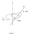
- Fig. 5 is a view showing a locus of the center of a slipper
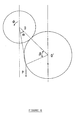
- Fig. 6 is a view showing the layout of a rocker.
- valve drive mechanism 1 designates an engine valve drive mechanism of this embodiment.
- the valve drive mechanism 1 is of a DOHC type in which intake valves 2 and exhaust valves 3 are radially disposed two and two for each cylinder and they are driven by an intake camshaft 4 and an exhaust camshaft 5, respectively.
- intake camshaft 4 On the intake and exhaust camshafts 4, 5 are provided three-dimensional cams 6 one for each of the intake and exhaust valves 2, 3.
- rocker arms 7 between the three-dimensional cams 6 and the intake and exhaust valves 2, 3.
- the rocker arm 7, as shown in Fig. 2 is comprised of a rocker pin 8 fixed to a cylinder head (not shown), a rocker arm body 9 supported on the rocker pin 8 for rocking movement, a slipper 10 provided at the rocking end of the rocker arm body 9, etc.
- the rocker arm 7 constitutes a cam follower.
- the axes of the rocker pins 8 are in a so-called skewed relation with the axes of the intake and exhaust camshafts 4, 5 and inclined, corresponding to the radially disposed intake and exhaust valves 2, 3, in relation to the camshafts 4, 5.
- the valve drive mechanism 1 is similar to the one disclosed in JP-A-H-12-170881.
- the three-dimensional cam 6, as shown in Fig. 3 and Fig. 4, has a cam face 11 inclined such that it decreases its diameter gradually in the axial direction from one end (left side end in Fig. 3) to the other end.
- the cam face 11 is a concave curved surface concaved radially inwardly.
- the cam face 11 is ground with a disk-like grinding wheel 12 into a given shape.
- a grinding surface 13 of the grinding wheel 12 has a convex curved surface of a radius of curvature smaller than the radius of curvature R (see Fig. 4) of the concave portion of the cam face 11.
- the radius of curvature of the grinding surface 13 of the grinding wheel 12 is designated by r in Fig. 4.
- the grinding machine having the grinding wheel 12 comprises grinding wheel drive means 21 for rotating the grinding wheel 12 at high speed, grinding wheel moving means 22 for moving the grinding wheel 12 radially and axially, and camshaft rotation means 23 for rotating the camshafts 4, 5 at low speed to move the grinding point of the grinding wheel 12 circumferentially.
- the grinding wheel moving means 22 and the camshaft rotation means 23 constitute grinding means according to this embodiment.
- the grinding means is designated by numeral 24 in Fig. 3.
- the grinding means 24 is arranged such that the cam face 11 is ground with the grinding wheel 12 based on a target cam profile of the three-dimensional cam 6 and a target shape of the cam face determined for each given rotation angle of the three-dimensional cam 6. Specifically, grinding is performed as shown in Fig. 4 such that the grinding point is moved in the rotational and axial directions of the three-dimensional cam 6 while a normal vector V1 of the grinding wheel at a grinding portion is kept in coincidence with a normal vector V2 of the target shape of the cam face.
- This grinding allows ground marks each constituted by a minute recess formed in the cam face 11 being arranged regularly in rows in the rotational and axial directions of the three-dimensional cam 6, respectively.
- the locus forms a curved surface. Since the center line is a straight line, a velocity vector and a normal vector of the locus surface have a feature of being calculated easily compared with an ordinary free curved surface.
- the curved surface constituted by the locus of the center line is referred to as a slipper center line locus surface. Since the slipper center line locus surface is one that is formed by sweeping a straight line, it has a feature of a ruled surface.
- determining the enveloping surface with respect to the slipper cylinder is to offset the slipper center line locus surface by the radius of the slipper.
- a velocity vector and a normal vector of the offset surface inherit the properties of the original surface such as the velocity vector and the normal vector, so that they can be calculated easily even if direct calculation is impossible. That is, if the velocity vector of the slipper center line for each cam rotation angle and the cam thrust position are established, the contact point between the slipper 10 and the three-dimensional cam 6 can be calculated uniquely.
- a slipper center point at a cam rotation angle ⁇ be P( ⁇ )
- a unit vector in the direction of the slipper center axis be A( ⁇ ).
- Fig. 6 is a drawing as viewed in the axial direction of the camshaft, and the Z-axis is on the point O. The direction of the Z'-axis coincides with an A vector.
- the rocker shaft and the slipper 10 shaft are slanted by ⁇ ° in the direction of a right hand screw around the X-axis,
- the surface of the three-dimensional cam 6 has the shape of the slipper center line locus surface offset by the radius r of the slipper 10.
- the cam face 11C( ⁇ , ⁇ ) can be represented by the following expression (4) using the slipper center line locus surface S( ⁇ , ⁇ ) and a normal vector N( ⁇ , ⁇ ).
- the position, the velocity vector and the second order differential vector of the cam face 11 (offset surface) can all be determined from the position, the velocity vector and the normal vector of the original surface (slipper center line locus surface).
- N ⁇ , N ⁇ , N ⁇ , N ⁇ and N ⁇ can be calculated using the first fundamental quantities E, F, and G and the second fundamental quantities l, m, and n of the curved surface as follows. While the first fundamental quantities are expressed in capital letters, the second fundamental quantities are expressed in lower-case letters to be distinguished from the normal vector N.
- the expression of the partial differential of a unit normal vector by a linear combination of the tangent vector is called the equation of Weingarten. Unless the differential value of the original surface unit normal vector is zero, the tangent vector of the offset surface differs from that of the original surface. This is because the Z-axis is not parallel to the Z'-axis in the present three-dimensional cam 6.
- the contact point with the grinding wheel can be obtained by successive calculations of the position, the tangent vector and the second order differential vector utilizing the foregoing properties.
- direct production of the cam face 11 is advantageous to design review or comparison with the inspection data.
- present calculation is performed of points on the cam curved surface for every angle of 1° and for every thrust direction of 1°, producing 36 drawings of the twin cubic surface of continuous curvature (one drawing/ten degrees).
- a free fitting method in which passing points are specified, is used as an interpolation of the curved surface.
- a vector at a specified point can be calculated using the original surface, breakage will occur unless tangent vector ratios at adjacent points are matched to each other.
- Placement of the intermediate cam curved surface allows the calculation of positions and normal lines to be performed directly from the cam curved surface, and contact point calculation and the valve layout can be treated separately without need of taking account of the valve layout and the position of the rocker arm 7 in the calculation of positions of the grinding wheel and the measurement piece.
- the position for each specified angle can be solved as a contact problem between the cam and the grinding wheel and measurement piece.
- the thrust direction since there is a change in the thrust direction, the situation is different from the flat cam in which preparation of grinding and measurement data is needed only for one cycle.
- the grinding wheel 12 used in this embodiment is of a so-called doughnut type. Specifically, it has a shape produced when a circle of radius r at a location offset by rO from the Z-axis is revolved around the Z-axis. Let E z represent rotation matrix around the Z-axis and e i represent a unit vector in the direction of each axis.
- the three-dimensional cam 6 shaped by the foregoing grinding procedure has multiple grinding marks each constituted by a minute recess formed in the cam face 11, arranged regularly in rows in the rotational and axial directions of the cam, respectively, the height of minute grooves formed by a plurality of grinding marks can be made smaller than the thickness of the oil film, so that cam load can be supported on the entire contact width.
- continuous oil film can be formed between the three-dimensional cam 6 and the slipper 10, providing a three-dimensional cam free from insufficient lubrication.
- the axis of the grinding wheel 12 can be made parallel to that of the camshaft, providing machining on a more ordinary grinding machine.
- no restriction due to interference with the grinding machine is placed on the axial length of the camshaft, so that camshafts for multi-cylinder engines can be manufactured.
- the height of minute grooves formed by a plurality of grinding marks can be made smaller than the thickness of the oil film, so that cam load can be supported on the entire contact width, thereby providing a three-dimensional cam free from insufficient lubrication.
- the axis of the grinding wheel 12 can be made parallel to that of the camshaft, providing machining on a more ordinary grinding machine, so that no restriction due to interference with the grinding machine is placed on the axial length of the camshaft.
- camshafts for multi-cylinder engines with three-dimensional cams can be manufactured.
- the description above discloses a three-dimensional cam adapted to press against a cam follower obliquely to the moving direction of a cam face, wherein the cam face is ground with a grinding wheel such that multiple ground marks each constituted by a minute recess formed in the cam face are arranged regularly in rows in the rotational and axial directions of the cam, respectively.
- the three-dimensional cam adapted to press against a cam follower obliquely to the moving direction of a cam face is characterized by minute grooves extending to the rotational direction of the cam formed by grinding the cam face with a grinding wheel which are multiply formed in condition arranged to the axial directions of the cam.
- the height of minute grooves formed by a plurality of ground marks can be made smaller than the thickness of the oil film, so that cam load can be supported on the entire contact width.
- the grooves are not connected to each other, wherein according to a version which is actually built there are provided 20 to 30 steps in the cam face having a space between each step of about 0.5 mm.
- a three-dimensional cam grinding machine comprising: a grinding wheel having a grinding surface constituted by a convex curved surface with a radius of curvature smaller than that of a concave curved portion of the cam face; grinding wheel drive means for rotating the grinding wheel; and grinding means for grinding the cam face with a grinding wheel based on a target cam profile and a target shape of the cam face set for each given rotation angle of the cam, said grinding means being adapted to grind the cam face with a grinding point moved in the rotational and axial directions while a normal vector of the grinding wheel at the grinding portion is kept in coincidence with a normal vector of the target cam face.
- the axis of the grinding wheel can be made parallel to the axis of the camshaft, so that a more ordinary grinding machine can be used.
- a three-dimensional cam free from insufficient lubrication wherein a cam face 11 is ground with a grinding wheel 12 such that grinding marks each constituted by a minute recess formed in the cam face 11 are arranged regularly in rows in the rotational and axial directions of the cam.
Landscapes
- Engineering & Computer Science (AREA)
- Mechanical Engineering (AREA)
- Valve-Gear Or Valve Arrangements (AREA)
- Grinding And Polishing Of Tertiary Curved Surfaces And Surfaces With Complex Shapes (AREA)
- Gears, Cams (AREA)
Abstract
Description
- The present invention relates to a valve drive mechanism according to the preamble portion of
claim 1, to an internal combustion engine according to the preamble portion ofclaim 9, and to a device and a method for grinding three-dimensional cams. - In particular, the present invention relates to a three-dimensional cam adapted to press against a cam follower obliquely to the moving direction of a cam face, and a three-dimensional cam grinding machine for grinding the cam face of the three-dimensional cam.
- As a three-dimensional cam adapted to press against a cam follower obliquely to the moving direction of the cam face is known, for example, as disclosed in JP-A-H12-170881, a valve drive cam in an engine having radially disposed intake and exhaust valves. The valve drive cam (three-dimensional cam) shown in the foregoing patent application publication is a cam in which the cam face is brought into sliding contact with a slipper of a rocker arm in an inclined relation, and the cam face is ground with a grinding wheel slanted in the same direction as the slipper.
- Specifically, the cam face is ground in such a manner that the axis of the grinding wheel is slanted in relation to the axis of the three-dimensional cam, the grinding wheel is moved along the cam profile in the radial direction of the cam, and the three-dimensional cam is rotated about its axis at a low speed. The grinding wheel is of a disk-shape with a radius of curvature the same as that of the slipper, and grinding is performed with the cylindrical outside circumferential surface of the grinding wheel brought into line contact with the cam face in the axial direction over the entire region.
- Since in the conventional three-dimensional cam described above, a phenomenon might occur that "a contact line between the cam and the slipper" and "a contact line between the cam and the grinding wheel" intersect with each other unless the grinding wheel used for grinding is equal to or smaller than the slipper in diameter, a problem is raised that a gap is produced between a cam face formed after grinding and the circumferential surface of the slipper, resulting in a larger contact pressure, which causes abrasion or insufficient lubrication.
- In addition, since the axis of the grinding wheel is slanted in relation to that of the camshaft during grinding, the length of the camshaft which can be mounted on a grinding machine is necessarily limited for the purpose of avoiding interference between the camshaft and the grinding machine. Only three-dimensional cams for single cylinder engines can be ground on the conventional grinding machine.
- Accordingly, it is an objective of the present invention to provide a valve drive mechanism as indicated above having an improved lubrication ability and showing a reduced abrasion, in particular of the three-dimensional cam.
- This objective is solved in an inventive manner by a valve drive mechanism, in particular for an internal combustion engine having intake and exhaust valves radially disposed for each cylinder of the internal combustion engine, comprising at least one three-dimensional cam adapted to press against a cam follower obliquely to a moving direction of a cam face, wherein the cam face comprises a plurality of lubricant collecting ground marks, wherein an oil film is provided between the three-dimensional cam and the cam follower.
- Thus, there is provided a valve drive mechanism with three-dimensional cams free from insufficient lubrication.
- Preferably, each ground mark is constituted by a minute groove formed in the cam face and extending in an rotational direction of the three-dimensional cam, wherein said ground marks are arranged regularly in an axial direction of the three-dimensional cam.
- According to a preferred embodiment, a height of the minute grooves constituting the ground marks is smaller than a thickness of the oil film lubricating the valve drive mechanism, wherein a continuous oil film is provided between the three-dimensional cam and the cam follower.
- Beneficially, 20 to 30 minute grooves are formed in parallel to each other in the cam face, wherein a distance between adjacent grooves in the axial direction of the three-dimensional cam is about 0.5 mm.
- It is further beneficial if the minute grooves are formed by grinding the cam face with a grinding wheel.
- According to a further preferred embodiment, the cam face of the three-dimensional cam is inclined.
- The three-dimensional cam may be further provided at an intake camshaft or an exhaust camshaft, wherein a diameter of the cam face decreases gradually in the axial direction of the respective camshaft.
- According to yet another preferred embodiment, the cam face is a concave curved surface, wherein the concave curved surface of the cam face is concaved radially inwardly.
- It is a further objective of the present invention to provide an internal combustion engine as indicated above having an improved lubrication and showing a reduced abrasion, in particular of the valve drive mechanism thereof.
- This objective is solved for an internal combustion engine comprising three, four or five intake and exhaust valves radially disposed for each cylinder, and a valve drive mechanism which complies with one of the embodiments of the valve drive mechanism discussed above.
- It is another objective of the present invention to provide a device and a method for grinding three-dimensional cams, enabling a simple and cost-effective manufacture of three-dimensional cams.
- According to the apparatus aspect, this objective is solved by a device for grinding three-dimensional cams, in particular for manufacturing a camshaft for a multi-valve internal combustion engine having at least one three-dimensional cam, comprising a grinding wheel having a grinding surface constituted by a convex curved surface with a radius of curvature smaller than that of a concave curved portion of a cam face of the three-dimensional cam.
- According to a preferred embodiment, there are provided a grinding wheel drive means for rotating the grinding wheel and grinding means comprises a grinding wheel moving means and a camshaft rotation means for grinding the cam face with the grinding wheel based on a target cam profile and a target shape of the cam face set for each given rotation angle of the three-dimensional cam.
- Preferably, said grinding means is adapted to grind the cam face with a grinding point moved in a rotational direction and/or an axial direction of the three-dimensional cam while a normal vector of the grinding wheel at a grinding portion is kept in coincidence with a normal vector of the target cam face.
- According to the method aspect, this objective is solved by a method for grinding three-dimensional cams, in particular for manufacturing at least one three-dimensional cam of a camshaft for a multi-valve internal combustion engine, wherein a cam face of the three-dimensional cam is ground with a grinding point moved in a rotational direction and/or an axial direction of the three-dimensional cam while a normal vector of the grinding wheel at a grinding portion is kept in coincidence with a normal vector of a target cam face.
- With the above device and method, it is particularly possible to provide a three-dimensional cam grinding machine capable of manufacturing a camshaft for a multi-cylinder engine with a three-dimensional cam.
- In the following, the present invention is discussed in greater detail with respect to several embodiments thereof in conjunction with the accompanying drawings, wherein:
- Fig. 1
- is a perspective view of an engine valve drive mechanism using a three-dimensional cam;
- Fig. 2
- is a sectional view of the three-dimensional cam and a rocker arm, on an enlarged scale;
- Fig. 3
- is a block diagram of a three-dimensional cam grinding machine;
- Fig. 4
- is a sectional view of a grinding portion, on an enlarged scale;
- Fig. 5
- is a view showing a locus of the center of a slipper; and
- Fig. 6
- is a view showing the layout of a rocker.
- Now, an embodiment of a three-dimensional cam and a three-dimensional cam grinding machine will be described below in detail by referring to Figs. 1 to 6.
- Fig. 1 is a perspective view of an engine valve drive mechanism using a three-dimensional cam; Fig. 2 is a sectional view of the three-dimensional cam and a rocker arm, on an enlarged scale; Fig. 3 is a block diagram of a three-dimensional cam grinding machine; Fig. 4 is a sectional view of a grinding portion, on an enlarged scale; Fig. 5 is a view showing a locus of the center of a slipper; and Fig. 6 is a view showing the layout of a rocker.
- In these figures,
numeral 1 designates an engine valve drive mechanism of this embodiment. Thevalve drive mechanism 1 is of a DOHC type in whichintake valves 2 andexhaust valves 3 are radially disposed two and two for each cylinder and they are driven by anintake camshaft 4 and anexhaust camshaft 5, respectively. On the intake andexhaust camshafts dimensional cams 6 one for each of the intake andexhaust valves - In the
valve drive mechanism 1 are providedrocker arms 7 between the three-dimensional cams 6 and the intake andexhaust valves rocker arm 7, as shown in Fig. 2, is comprised of arocker pin 8 fixed to a cylinder head (not shown), arocker arm body 9 supported on therocker pin 8 for rocking movement, aslipper 10 provided at the rocking end of therocker arm body 9, etc. Therocker arm 7 constitutes a cam follower. - The axes of the
rocker pins 8 are in a so-called skewed relation with the axes of the intake andexhaust camshafts exhaust valves camshafts valve drive mechanism 1 is similar to the one disclosed in JP-A-H-12-170881. - The three-
dimensional cam 6, as shown in Fig. 3 and Fig. 4, has acam face 11 inclined such that it decreases its diameter gradually in the axial direction from one end (left side end in Fig. 3) to the other end. Thecam face 11 is a concave curved surface concaved radially inwardly. - In this embodiment, the
cam face 11 is ground with a disk-like grindingwheel 12 into a given shape. Agrinding surface 13 of thegrinding wheel 12 has a convex curved surface of a radius of curvature smaller than the radius of curvature R (see Fig. 4) of the concave portion of thecam face 11. The radius of curvature of thegrinding surface 13 of thegrinding wheel 12 is designated by r in Fig. 4. - The grinding machine having the grinding
wheel 12 comprises grinding wheel drive means 21 for rotating the grindingwheel 12 at high speed, grinding wheel moving means 22 for moving the grindingwheel 12 radially and axially, and camshaft rotation means 23 for rotating thecamshafts wheel 12 circumferentially. The grinding wheel moving means 22 and the camshaft rotation means 23 constitute grinding means according to this embodiment. The grinding means is designated bynumeral 24 in Fig. 3. - The grinding means 24 is arranged such that the
cam face 11 is ground with thegrinding wheel 12 based on a target cam profile of the three-dimensional cam 6 and a target shape of the cam face determined for each given rotation angle of the three-dimensional cam 6. Specifically, grinding is performed as shown in Fig. 4 such that the grinding point is moved in the rotational and axial directions of the three-dimensional cam 6 while a normal vector V1 of the grinding wheel at a grinding portion is kept in coincidence with a normal vector V2 of the target shape of the cam face. This grinding allows ground marks each constituted by a minute recess formed in thecam face 11 being arranged regularly in rows in the rotational and axial directions of the three-dimensional cam 6, respectively. - Now, the procedure of determining the target shape of the
cam face 11 will be described by referring to Fig. 5 and Fig. 6. - Suppose a coordinate system in which the three-
dimensional cam 6 is fixed and theslipper 10 androcker arm 7 as a whole rotates around the camshaft. An enveloping surface of the cam rotation angle with respect to the slipper cylinder constitutes thecam face 11. If the position of the center line of the slipper for each cam rotation angle is determined successively, the locus forms a curved surface. Since the center line is a straight line, a velocity vector and a normal vector of the locus surface have a feature of being calculated easily compared with an ordinary free curved surface. The curved surface constituted by the locus of the center line is referred to as a slipper center line locus surface. Since the slipper center line locus surface is one that is formed by sweeping a straight line, it has a feature of a ruled surface. - Since the slipper is of a cylindrical shape, determining the enveloping surface with respect to the slipper cylinder is to offset the slipper center line locus surface by the radius of the slipper. A velocity vector and a normal vector of the offset surface inherit the properties of the original surface such as the velocity vector and the normal vector, so that they can be calculated easily even if direct calculation is impossible. That is, if the velocity vector of the slipper center line for each cam rotation angle and the cam thrust position are established, the contact point between the
slipper 10 and the three-dimensional cam 6 can be calculated uniquely. - Let a slipper center point at a cam rotation angle be P(), and a unit vector in the direction of the slipper center axis be A(). The slipper center line locus surface S(, ξ) is defined as follows (see Fig. 5):
rocker arm 7 moving around the camshaft at a constant speed, and the center velocity of theslipper 10 rotating around the rocker shaft, using a rocker center line unit vector Z' and a rocker center point O' (see Fig. 6 of the rocker layout). - Fig. 6 is a drawing as viewed in the axial direction of the camshaft, and the Z-axis is on the point O. The direction of the Z'-axis coincides with an A vector. In Fig. 6, if with the camshaft taken as a reference line, the rocker shaft and the
slipper 10 shaft are slanted by δ° in the direction of a right hand screw around the X-axis, - Z: unit vector in the direction of the camshaft = (0, 0, 1),
- O: direction of the cam center axis = (0, 0, 0),
- O': rocker center point,
- Z': unit vector in the direction of the rocker shaft = (0, -sin δ, cos δ),
- P: slipper center point, and
- Z': unit vector in the direction of the slipper shaft = (0, -sin δ, cos δ).
-
- A≡dA d=Z×A, where symbol × represents the vector product. Since a normal direction is given as the vector product of the velocity vector of the curved surface, a unit normal vector is written as:
- The surface of the three-
dimensional cam 6 has the shape of the slipper center line locus surface offset by the radius r of theslipper 10. The cam face 11C(, ξ) can be represented by the following expression (4) using the slipper center line locus surface S(, ξ) and a normal vector N(, ξ). The position, the velocity vector and the second order differential vector of the cam face 11 (offset surface) can all be determined from the position, the velocity vector and the normal vector of the original surface (slipper center line locus surface).
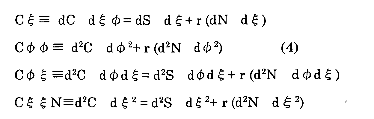
- Where N, Nξ, N, Nξ and Nξξ can be calculated using the first fundamental quantities E, F, and G and the second fundamental quantities l, m, and n of the curved surface as follows. While the first fundamental quantities are expressed in capital letters, the second fundamental quantities are expressed in lower-case letters to be distinguished from the normal vector N. The expression of the partial differential of a unit normal vector by a linear combination of the tangent vector is called the equation of Weingarten. Unless the differential value of the original surface unit normal vector is zero, the tangent vector of the offset surface differs from that of the original surface. This is because the Z-axis is not parallel to the Z'-axis in the present three-
dimensional cam 6.
- Although properties of the offset surface inherit those of the original surface, calculation of the position of the offset surface necessitates information on the position and the tangent vector of the original surface, and calculation of the tangent vector of the offset surface necessitates information of a higher class such as the position, the tangent vector and the second order differential vector of the original surface.
- The contact point with the grinding wheel can be obtained by successive calculations of the position, the tangent vector and the second order differential vector utilizing the foregoing properties. However, direct production of the
cam face 11 is advantageous to design review or comparison with the inspection data. Thus, present calculation is performed of points on the cam curved surface for every angle of 1° and for every thrust direction of 1°, producing 36 drawings of the twin cubic surface of continuous curvature (one drawing/ten degrees). A free fitting method in which passing points are specified, is used as an interpolation of the curved surface. Although a vector at a specified point can be calculated using the original surface, breakage will occur unless tangent vector ratios at adjacent points are matched to each other. The free fitting method in which tangent vector ratios are matched to each other and passing points are specified, is used to dispense with special post-processing. Although error develops in a rising section where change in curvature is discontinuous, no problem is raised because accuracy check at the time of inspection data preparation showed that the error was 0.1 µm or less. - Placement of the intermediate cam curved surface allows the calculation of positions and normal lines to be performed directly from the cam curved surface, and contact point calculation and the valve layout can be treated separately without need of taking account of the valve layout and the position of the
rocker arm 7 in the calculation of positions of the grinding wheel and the measurement piece. In the case of a radial cam, as in a flat cam, the position for each specified angle can be solved as a contact problem between the cam and the grinding wheel and measurement piece. In the radial cam, however, since there is a change in the thrust direction, the situation is different from the flat cam in which preparation of grinding and measurement data is needed only for one cycle. - The grinding
wheel 12 used in this embodiment is of a so-called doughnut type. Specifically, it has a shape produced when a circle of radius r at a location offset by rO from the Z-axis is revolved around the Z-axis. Let Ez represent rotation matrix around the Z-axis and ei represent a unit vector in the direction of each axis. The shape of thegrinding wheel 12 can be written as: - This means that the contact position between the three-
dimensional cam 6 and thegrinding wheel 12 at a specified thrust position and for a specified angle from the cam center line is calculated. Under the restriction of equations - In the actual calculation, there is no need of finding the contact point between the cam and the doughnut shape if only the contact point between the cam and the sphere at the top end is calculated, and the center of the doughnut shape, if required, can be obtained easily by two-dimensional calculation.
- Therefore, since the three-
dimensional cam 6 shaped by the foregoing grinding procedure has multiple grinding marks each constituted by a minute recess formed in thecam face 11, arranged regularly in rows in the rotational and axial directions of the cam, respectively, the height of minute grooves formed by a plurality of grinding marks can be made smaller than the thickness of the oil film, so that cam load can be supported on the entire contact width. As a result, since continuous oil film can be formed between the three-dimensional cam 6 and theslipper 10, providing a three-dimensional cam free from insufficient lubrication. - In addition, in the three-dimensional cam grinding machine of this embodiment, grinding is performed with a grinding point moved in the rotational and axial directions while a normal vector of the
grinding wheel 12 at the grinding portion is kept in coincidence with a normal vector of thetarget cam face 11. Therefore, the axis of thegrinding wheel 12 can be made parallel to that of the camshaft, providing machining on a more ordinary grinding machine. Thus, no restriction due to interference with the grinding machine is placed on the axial length of the camshaft, so that camshafts for multi-cylinder engines can be manufactured. - According to this embodiment as described above, the height of minute grooves formed by a plurality of grinding marks can be made smaller than the thickness of the oil film, so that cam load can be supported on the entire contact width, thereby providing a three-dimensional cam free from insufficient lubrication.
- Further, according to this embodiment, the axis of the
grinding wheel 12 can be made parallel to that of the camshaft, providing machining on a more ordinary grinding machine, so that no restriction due to interference with the grinding machine is placed on the axial length of the camshaft. As a result, camshafts for multi-cylinder engines with three-dimensional cams can be manufactured. - The description above discloses a three-dimensional cam adapted to press against a cam follower obliquely to the moving direction of a cam face, wherein the cam face is ground with a grinding wheel such that multiple ground marks each constituted by a minute recess formed in the cam face are arranged regularly in rows in the rotational and axial directions of the cam, respectively.
- To be precise, the three-dimensional cam adapted to press against a cam follower obliquely to the moving direction of a cam face is characterized by minute grooves extending to the rotational direction of the cam formed by grinding the cam face with a grinding wheel which are multiply formed in condition arranged to the axial directions of the cam.
- Accordingly, the height of minute grooves formed by a plurality of ground marks can be made smaller than the thickness of the oil film, so that cam load can be supported on the entire contact width.
- Thus, according to the embodiments described above, the grooves are not connected to each other, wherein according to a version which is actually built there are provided 20 to 30 steps in the cam face having a space between each step of about 0.5 mm.
- Even though the description above mainly refers to an internal combustion engine having four intake and exhaust valves, the present invention is not limited thereto. In fact, at least three valves are sufficient for radially disposing and, in particular, the concepts of the present invention apply to five valve engine technology.
- The description above further discloses a three-dimensional cam grinding machine, comprising: a grinding wheel having a grinding surface constituted by a convex curved surface with a radius of curvature smaller than that of a concave curved portion of the cam face; grinding wheel drive means for rotating the grinding wheel; and grinding means for grinding the cam face with a grinding wheel based on a target cam profile and a target shape of the cam face set for each given rotation angle of the cam, said grinding means being adapted to grind the cam face with a grinding point moved in the rotational and axial directions while a normal vector of the grinding wheel at the grinding portion is kept in coincidence with a normal vector of the target cam face.
- Accordingly, the axis of the grinding wheel can be made parallel to the axis of the camshaft, so that a more ordinary grinding machine can be used.
- Briefly summarizing the above, there is provided a three-dimensional cam free from insufficient lubrication, wherein a
cam face 11 is ground with agrinding wheel 12 such that grinding marks each constituted by a minute recess formed in thecam face 11 are arranged regularly in rows in the rotational and axial directions of the cam.
Claims (13)
- Valve drive mechanism, in particular for an internal combustion engine having intake and exhaust valves radially disposed for each cylinder of the internal combustion engine, comprising at least one three-dimensional cam (6) adapted to press against a cam follower (7) obliquely to a moving direction of a cam face (11), characterized in that the cam face (11) comprises a plurality of lubricant collecting ground marks, wherein an oil film is provided between the three-dimensional cam (6) and the cam follower (7).
- Valve drive mechanism according to claim 1, characterized in that each ground mark is constituted by a minute groove formed in the cam face (11) and extending in an rotational direction of the three-dimensional cam (6), wherein said plurality of ground marks are arranged regularly in an axial direction of the three-dimensional cam (6).
- Valve drive mechanism according to claim 2, characterized in that a height of the minute grooves constituting the ground marks is smaller than a thickness of the oil film lubricating the valve drive mechanism, wherein a continuous oil film is provided between the three-dimensional cam (6) and the cam follower (7).
- Valve drive mechanism according to claim 2 or 3, characterized by 20 to 30 minute grooves formed in parallel to each other in the cam face (11), wherein a distance between adjacent grooves in the axial direction of the three-dimensional cam (6) is about 0.5 mm.
- Valve drive mechanism according to at least one of the preceding claims 2 to 4, characterized in that the minute grooves are formed by grinding the cam face (11) with a grinding wheel.
- Valve drive mechanism according to at least one of the preceding claims 1 to 5, characterized in that the cam face (11) of the three-dimensional cam (6) is inclined.
- Valve drive mechanism according to at least one of the preceding claims 1 to 6, characterized in that the three-dimensional cam (11) is provided at an intake camshaft (4) or an exhaust camshaft (5), wherein a diameter of the cam face (11) decreases gradually in the axial direction of the respective camshaft (4,5).
- Valve drive mechanism according to at least one of the preceding claims 1 to 7, characterized in that the cam face (11) is a concave curved surface, wherein the concave curved surface of the cam face (11) is concaved radially inwardly.
- Internal combustion engine comprising three, four or five intake and exhaust valves radially disposed for each cylinder, characterized by a valve drive mechanism having the features of at least one of the preceding claims 1 to 8.
- Device for grinding three-dimensional cams, in particular for manufacturing a camshaft (4,5) for a multi-valve internal combustion engine having at least one three-dimensional cam (6), comprising a grinding wheel (12) having a grinding surface (13) constituted by a convex curved surface with a radius of curvature (r) smaller than that of a concave curved portion (R) of a cam face (11) of the three-dimensional cam (6).
- Device for grinding three-dimensional cams according to claim 10, characterized by a grinding wheel drive means (21) for rotating the grinding wheel (12), and grinding means (24) comprises a grinding wheel moving means (22) and a camshaft rotation means (23) for grinding the cam face (11) with the grinding wheel (12) based on a target cam profile and a target shape of the cam face set for each given rotation angle of the three-dimensional cam (6).
- Device for grinding three-dimensional cams according to claim 10 or 11, characterized in that said grinding means (24) is adapted to grind the cam face (11) with a grinding point moved in a rotational direction and/or an axial direction of the three-dimensional cam (6) while a normal vector (V1) of the grinding wheel (12) at a grinding portion is kept in coincidence with a normal vector (V2) of the target cam face.
- Method for grinding three-dimensional cams, in particular for manufacturing at least one three-dimensional cam (6) of a camshaft for a multi-valve internal combustion engine, wherein a cam face (11) of the three-dimensional cam (6) is ground with a grinding point moved in a rotational direction and/or an axial direction of the three-dimensional cam (6) while a normal vector (V1) of the grinding wheel (12) at a grinding portion is kept in coincidence with a normal vector (V2) of a target cam face.
Applications Claiming Priority (2)
| Application Number | Priority Date | Filing Date | Title |
|---|---|---|---|
| JP2001176881A JP4627121B2 (en) | 2001-06-12 | 2001-06-12 | 3D cam and 3D cam grinding machine |
| JP2001176881 | 2001-06-12 |
Publications (2)
| Publication Number | Publication Date |
|---|---|
| EP1270878A2 true EP1270878A2 (en) | 2003-01-02 |
| EP1270878A3 EP1270878A3 (en) | 2007-07-25 |
Family
ID=19017809
Family Applications (1)
| Application Number | Title | Priority Date | Filing Date |
|---|---|---|---|
| EP02013411A Withdrawn EP1270878A3 (en) | 2001-06-12 | 2002-06-12 | Valve drive mechanism for internal combustion engine; device and method for grinding three-dimensional cams |
Country Status (3)
| Country | Link |
|---|---|
| US (1) | US6834629B2 (en) |
| EP (1) | EP1270878A3 (en) |
| JP (1) | JP4627121B2 (en) |
Cited By (1)
| Publication number | Priority date | Publication date | Assignee | Title |
|---|---|---|---|---|
| DE102007032638A1 (en) * | 2007-07-11 | 2009-01-15 | Bayerische Motoren Werke Aktiengesellschaft | Internal combustion engine with a crankshaft and at least one cylinder head and motor vehicle with such an internal combustion engine |
Families Citing this family (3)
| Publication number | Priority date | Publication date | Assignee | Title |
|---|---|---|---|---|
| DE102011106395A1 (en) * | 2011-07-02 | 2013-01-03 | Man Truck & Bus Ag | Valve control for at least one valve of an internal combustion engine |
| WO2015125231A1 (en) * | 2014-02-19 | 2015-08-27 | 日鍛バルブ株式会社 | Processing apparatus and burr removal device |
| CN115401536B (en) * | 2022-08-30 | 2024-04-12 | 深圳数马电子技术有限公司 | Reamer grinding method, device, numerical control machine, computer equipment and storage medium |
Citations (4)
| Publication number | Priority date | Publication date | Assignee | Title |
|---|---|---|---|---|
| GB481722A (en) | 1936-10-27 | 1938-03-16 | Deckel Friedrich | Improved method of grinding cam shafts |
| US5630953A (en) | 1993-05-13 | 1997-05-20 | Maschinenfabrik Gehring Gmbh & Co. | Method of fine-machining a workpiece surface to be supplied with a lubricant during operation of the workpiece |
| EP0990774A1 (en) | 1998-09-30 | 2000-04-05 | Yamaha Hatsudoki Kabushiki Kaisha | Three-dimensional cam device and method of making a three-dimensional cam for a valve drive system for engines |
| JP2000170881A (en) | 1998-09-30 | 2000-06-23 | Yamaha Motor Co Ltd | Three-dimensional cam device, engine valve gear, and method of manufacturing three-dimensional cam for engine valve gear |
Family Cites Families (12)
| Publication number | Priority date | Publication date | Assignee | Title |
|---|---|---|---|---|
| US3618573A (en) * | 1969-05-28 | 1971-11-09 | Trw Inc | Variable cam and follower assembly |
| AT382933B (en) * | 1984-03-14 | 1987-04-27 | Weichsler Hermann | VALVE ACTUATION FOR LIFTING PISTON - INTERNAL COMBUSTION ENGINES |
| DE3444901A1 (en) | 1984-12-08 | 1986-06-12 | Audi AG, 8070 Ingolstadt | Cam control |
| IT1233237B (en) * | 1989-08-04 | 1992-03-20 | Fiat Auto Spa | CYLINDER HEAD FOR AN INTERNAL COMBUSTION ENGINE WITH FIVE VALVES PER CYLINDER |
| JP2811991B2 (en) * | 1991-04-23 | 1998-10-15 | 日産自動車株式会社 | Camshaft for internal combustion engine and processing method thereof |
| JP2656404B2 (en) * | 1991-08-28 | 1997-09-24 | エヌティエヌ株式会社 | Cam follower with roller for engine valve train |
| JPH05212658A (en) * | 1992-01-31 | 1993-08-24 | Maruei Kikai Seisakusho:Kk | Work grinding device by three-dimensional grinding machine with vertical computer numerical control device |
| EP0867601B1 (en) * | 1997-03-27 | 2003-01-22 | Toyota Jidosha Kabushiki Kaisha | Valve driving apparatus for engine |
| JPH11165248A (en) | 1997-12-08 | 1999-06-22 | Toyota Motor Corp | Cam grinding method and grinding apparatus, cam grinding wheel and dresser |
| DE19801606A1 (en) | 1998-01-17 | 1999-07-22 | Audi Ag | Cylinder head |
| US5921210A (en) * | 1998-09-10 | 1999-07-13 | Chrysler Corporation | Tappet assembly for the valve train of an internal combustion engine |
| US6170449B1 (en) * | 1998-09-30 | 2001-01-09 | Yamaha Hatsudoki Kabushiki Kaisha | Valve operating system for engine |
-
2001
- 2001-06-12 JP JP2001176881A patent/JP4627121B2/en not_active Expired - Fee Related
-
2002
- 2002-06-12 US US10/170,256 patent/US6834629B2/en not_active Expired - Fee Related
- 2002-06-12 EP EP02013411A patent/EP1270878A3/en not_active Withdrawn
Patent Citations (4)
| Publication number | Priority date | Publication date | Assignee | Title |
|---|---|---|---|---|
| GB481722A (en) | 1936-10-27 | 1938-03-16 | Deckel Friedrich | Improved method of grinding cam shafts |
| US5630953A (en) | 1993-05-13 | 1997-05-20 | Maschinenfabrik Gehring Gmbh & Co. | Method of fine-machining a workpiece surface to be supplied with a lubricant during operation of the workpiece |
| EP0990774A1 (en) | 1998-09-30 | 2000-04-05 | Yamaha Hatsudoki Kabushiki Kaisha | Three-dimensional cam device and method of making a three-dimensional cam for a valve drive system for engines |
| JP2000170881A (en) | 1998-09-30 | 2000-06-23 | Yamaha Motor Co Ltd | Three-dimensional cam device, engine valve gear, and method of manufacturing three-dimensional cam for engine valve gear |
Cited By (2)
| Publication number | Priority date | Publication date | Assignee | Title |
|---|---|---|---|---|
| DE102007032638A1 (en) * | 2007-07-11 | 2009-01-15 | Bayerische Motoren Werke Aktiengesellschaft | Internal combustion engine with a crankshaft and at least one cylinder head and motor vehicle with such an internal combustion engine |
| US8307798B2 (en) | 2007-07-11 | 2012-11-13 | Bayerische Motoren Werke Aktiengesellschaft | Internal combustion engine with a crankshaft and at least one cylinder head as well as a motor vehicle with such an internal combustion engine |
Also Published As
| Publication number | Publication date |
|---|---|
| JP4627121B2 (en) | 2011-02-09 |
| JP2002372126A (en) | 2002-12-26 |
| US20020187734A1 (en) | 2002-12-12 |
| EP1270878A3 (en) | 2007-07-25 |
| US6834629B2 (en) | 2004-12-28 |
Similar Documents
| Publication | Publication Date | Title |
|---|---|---|
| US9115613B2 (en) | Splined-shaft connection and valve timing mechanism with a splined-shaft connection between a camshaft and displaceable cam carriers | |
| JP4330618B2 (en) | Valve mechanism for internal combustion engine with cylinder head | |
| US7472671B2 (en) | Valve engine | |
| US20100326270A1 (en) | Process for roughening metal surfaces | |
| WO2020099625A1 (en) | Reversible target for a 3-, 4- or 6-cylinder engine | |
| US6170449B1 (en) | Valve operating system for engine | |
| CN101688554B (en) | Needle roller bearing and crankshaft support structure | |
| CN102418573A (en) | Valve lifter for internal combustion engine | |
| JP4326159B2 (en) | Ball bearing | |
| US6834629B2 (en) | Three dimensional cam, grinding method and grinding apparatus | |
| JP4464767B2 (en) | Roller with cage | |
| JP3906754B2 (en) | Crank bearing | |
| CN103711796B (en) | Bearing and cam gear | |
| Volodymyr et al. | Ensuring a stable relative area of burnishing of partially regular microrelief formed on end surfaces of rotary bodies | |
| US6256897B1 (en) | Three dimensional cam, method and apparatus for measuring three dimensional cam profile, and valve drive apparatus | |
| US20020000214A1 (en) | Rocker arm | |
| GB2206179A (en) | Improvements in or relating to driving connections between two rotatable bodies | |
| JP4361635B2 (en) | ENGINE VALVE DEVICE, METHOD FOR PRODUCING THREE-DIMENSIONAL CAM FOR ENGINE VALVE | |
| JP5577969B2 (en) | Tappet roller | |
| WO1992006282A1 (en) | Improvements in or relating to driving connections between two rotatable bodies | |
| CN109306882B (en) | Rocker arm device | |
| EP0990774B1 (en) | Three-dimensional cam device and method of making a three-dimensional cam for a valve drive system for engines | |
| CN115087798A (en) | Gear for camshaft and synchronization method using such gear | |
| CN107435627B (en) | Conveying elements of rotary pumps | |
| KR20150048335A (en) | the burnishing method of camshaft for high hardness |
Legal Events
| Date | Code | Title | Description |
|---|---|---|---|
| PUAI | Public reference made under article 153(3) epc to a published international application that has entered the european phase |
Free format text: ORIGINAL CODE: 0009012 |
|
| AK | Designated contracting states |
Kind code of ref document: A2 Designated state(s): AT BE CH CY DE DK ES FI FR GB GR IE IT LI LU MC NL PT SE TR |
|
| AX | Request for extension of the european patent |
Free format text: AL;LT;LV;MK;RO;SI |
|
| PUAL | Search report despatched |
Free format text: ORIGINAL CODE: 0009013 |
|
| AK | Designated contracting states |
Kind code of ref document: A3 Designated state(s): AT BE CH CY DE DK ES FI FR GB GR IE IT LI LU MC NL PT SE TR |
|
| AX | Request for extension of the european patent |
Extension state: AL LT LV MK RO SI |
|
| 17P | Request for examination filed |
Effective date: 20080118 |
|
| AKX | Designation fees paid |
Designated state(s): DE FR GB |
|
| 17Q | First examination report despatched |
Effective date: 20091012 |
|
| STAA | Information on the status of an ep patent application or granted ep patent |
Free format text: STATUS: THE APPLICATION IS DEEMED TO BE WITHDRAWN |
|
| 18D | Application deemed to be withdrawn |
Effective date: 20130910 |