EP1270303A2 - Method for controlling the power train of a hybrid vehicle - Google Patents
Method for controlling the power train of a hybrid vehicle Download PDFInfo
- Publication number
- EP1270303A2 EP1270303A2 EP02100523A EP02100523A EP1270303A2 EP 1270303 A2 EP1270303 A2 EP 1270303A2 EP 02100523 A EP02100523 A EP 02100523A EP 02100523 A EP02100523 A EP 02100523A EP 1270303 A2 EP1270303 A2 EP 1270303A2
- Authority
- EP
- European Patent Office
- Prior art keywords
- data
- route
- energy
- operating strategy
- drive train
- Prior art date
- Legal status (The legal status is an assumption and is not a legal conclusion. Google has not performed a legal analysis and makes no representation as to the accuracy of the status listed.)
- Granted
Links
Images
Classifications
-
- B—PERFORMING OPERATIONS; TRANSPORTING
- B60—VEHICLES IN GENERAL
- B60W—CONJOINT CONTROL OF VEHICLE SUB-UNITS OF DIFFERENT TYPE OR DIFFERENT FUNCTION; CONTROL SYSTEMS SPECIALLY ADAPTED FOR HYBRID VEHICLES; ROAD VEHICLE DRIVE CONTROL SYSTEMS FOR PURPOSES NOT RELATED TO THE CONTROL OF A PARTICULAR SUB-UNIT
- B60W50/00—Details of control systems for road vehicle drive control not related to the control of a particular sub-unit, e.g. process diagnostic or vehicle driver interfaces
- B60W50/0097—Predicting future conditions
-
- B—PERFORMING OPERATIONS; TRANSPORTING
- B60—VEHICLES IN GENERAL
- B60W—CONJOINT CONTROL OF VEHICLE SUB-UNITS OF DIFFERENT TYPE OR DIFFERENT FUNCTION; CONTROL SYSTEMS SPECIALLY ADAPTED FOR HYBRID VEHICLES; ROAD VEHICLE DRIVE CONTROL SYSTEMS FOR PURPOSES NOT RELATED TO THE CONTROL OF A PARTICULAR SUB-UNIT
- B60W20/00—Control systems specially adapted for hybrid vehicles
- B60W20/10—Controlling the power contribution of each of the prime movers to meet required power demand
- B60W20/12—Controlling the power contribution of each of the prime movers to meet required power demand using control strategies taking into account route information
-
- B—PERFORMING OPERATIONS; TRANSPORTING
- B60—VEHICLES IN GENERAL
- B60K—ARRANGEMENT OR MOUNTING OF PROPULSION UNITS OR OF TRANSMISSIONS IN VEHICLES; ARRANGEMENT OR MOUNTING OF PLURAL DIVERSE PRIME-MOVERS IN VEHICLES; AUXILIARY DRIVES FOR VEHICLES; INSTRUMENTATION OR DASHBOARDS FOR VEHICLES; ARRANGEMENTS IN CONNECTION WITH COOLING, AIR INTAKE, GAS EXHAUST OR FUEL SUPPLY OF PROPULSION UNITS IN VEHICLES
- B60K6/00—Arrangement or mounting of plural diverse prime-movers for mutual or common propulsion, e.g. hybrid propulsion systems comprising electric motors and internal combustion engines ; Control systems therefor, i.e. systems controlling two or more prime movers, or controlling one of these prime movers and any of the transmission, drive or drive units Informative references: mechanical gearings with secondary electric drive F16H3/72; arrangements for handling mechanical energy structurally associated with the dynamo-electric machine H02K7/00; machines comprising structurally interrelated motor and generator parts H02K51/00; dynamo-electric machines not otherwise provided for in H02K see H02K99/00
- B60K6/20—Arrangement or mounting of plural diverse prime-movers for mutual or common propulsion, e.g. hybrid propulsion systems comprising electric motors and internal combustion engines ; Control systems therefor, i.e. systems controlling two or more prime movers, or controlling one of these prime movers and any of the transmission, drive or drive units Informative references: mechanical gearings with secondary electric drive F16H3/72; arrangements for handling mechanical energy structurally associated with the dynamo-electric machine H02K7/00; machines comprising structurally interrelated motor and generator parts H02K51/00; dynamo-electric machines not otherwise provided for in H02K see H02K99/00 the prime-movers consisting of electric motors and internal combustion engines, e.g. HEVs
- B60K6/42—Arrangement or mounting of plural diverse prime-movers for mutual or common propulsion, e.g. hybrid propulsion systems comprising electric motors and internal combustion engines ; Control systems therefor, i.e. systems controlling two or more prime movers, or controlling one of these prime movers and any of the transmission, drive or drive units Informative references: mechanical gearings with secondary electric drive F16H3/72; arrangements for handling mechanical energy structurally associated with the dynamo-electric machine H02K7/00; machines comprising structurally interrelated motor and generator parts H02K51/00; dynamo-electric machines not otherwise provided for in H02K see H02K99/00 the prime-movers consisting of electric motors and internal combustion engines, e.g. HEVs characterised by the architecture of the hybrid electric vehicle
- B60K6/48—Parallel type
- B60K6/485—Motor-assist type
-
- B—PERFORMING OPERATIONS; TRANSPORTING
- B60—VEHICLES IN GENERAL
- B60K—ARRANGEMENT OR MOUNTING OF PROPULSION UNITS OR OF TRANSMISSIONS IN VEHICLES; ARRANGEMENT OR MOUNTING OF PLURAL DIVERSE PRIME-MOVERS IN VEHICLES; AUXILIARY DRIVES FOR VEHICLES; INSTRUMENTATION OR DASHBOARDS FOR VEHICLES; ARRANGEMENTS IN CONNECTION WITH COOLING, AIR INTAKE, GAS EXHAUST OR FUEL SUPPLY OF PROPULSION UNITS IN VEHICLES
- B60K6/00—Arrangement or mounting of plural diverse prime-movers for mutual or common propulsion, e.g. hybrid propulsion systems comprising electric motors and internal combustion engines ; Control systems therefor, i.e. systems controlling two or more prime movers, or controlling one of these prime movers and any of the transmission, drive or drive units Informative references: mechanical gearings with secondary electric drive F16H3/72; arrangements for handling mechanical energy structurally associated with the dynamo-electric machine H02K7/00; machines comprising structurally interrelated motor and generator parts H02K51/00; dynamo-electric machines not otherwise provided for in H02K see H02K99/00
- B60K6/20—Arrangement or mounting of plural diverse prime-movers for mutual or common propulsion, e.g. hybrid propulsion systems comprising electric motors and internal combustion engines ; Control systems therefor, i.e. systems controlling two or more prime movers, or controlling one of these prime movers and any of the transmission, drive or drive units Informative references: mechanical gearings with secondary electric drive F16H3/72; arrangements for handling mechanical energy structurally associated with the dynamo-electric machine H02K7/00; machines comprising structurally interrelated motor and generator parts H02K51/00; dynamo-electric machines not otherwise provided for in H02K see H02K99/00 the prime-movers consisting of electric motors and internal combustion engines, e.g. HEVs
- B60K6/50—Architecture of the driveline characterised by arrangement or kind of transmission units
- B60K6/54—Transmission for changing ratio
-
- B—PERFORMING OPERATIONS; TRANSPORTING
- B60—VEHICLES IN GENERAL
- B60L—PROPULSION OF ELECTRICALLY-PROPELLED VEHICLES; SUPPLYING ELECTRIC POWER FOR AUXILIARY EQUIPMENT OF ELECTRICALLY-PROPELLED VEHICLES; ELECTRODYNAMIC BRAKE SYSTEMS FOR VEHICLES IN GENERAL; MAGNETIC SUSPENSION OR LEVITATION FOR VEHICLES; MONITORING OPERATING VARIABLES OF ELECTRICALLY-PROPELLED VEHICLES; ELECTRIC SAFETY DEVICES FOR ELECTRICALLY-PROPELLED VEHICLES
- B60L1/00—Supplying electric power to auxiliary equipment of vehicles
- B60L1/003—Supplying electric power to auxiliary equipment of vehicles to auxiliary motors, e.g. for pumps, compressors
-
- B—PERFORMING OPERATIONS; TRANSPORTING
- B60—VEHICLES IN GENERAL
- B60L—PROPULSION OF ELECTRICALLY-PROPELLED VEHICLES; SUPPLYING ELECTRIC POWER FOR AUXILIARY EQUIPMENT OF ELECTRICALLY-PROPELLED VEHICLES; ELECTRODYNAMIC BRAKE SYSTEMS FOR VEHICLES IN GENERAL; MAGNETIC SUSPENSION OR LEVITATION FOR VEHICLES; MONITORING OPERATING VARIABLES OF ELECTRICALLY-PROPELLED VEHICLES; ELECTRIC SAFETY DEVICES FOR ELECTRICALLY-PROPELLED VEHICLES
- B60L1/00—Supplying electric power to auxiliary equipment of vehicles
- B60L1/02—Supplying electric power to auxiliary equipment of vehicles to electric heating circuits
-
- B—PERFORMING OPERATIONS; TRANSPORTING
- B60—VEHICLES IN GENERAL
- B60L—PROPULSION OF ELECTRICALLY-PROPELLED VEHICLES; SUPPLYING ELECTRIC POWER FOR AUXILIARY EQUIPMENT OF ELECTRICALLY-PROPELLED VEHICLES; ELECTRODYNAMIC BRAKE SYSTEMS FOR VEHICLES IN GENERAL; MAGNETIC SUSPENSION OR LEVITATION FOR VEHICLES; MONITORING OPERATING VARIABLES OF ELECTRICALLY-PROPELLED VEHICLES; ELECTRIC SAFETY DEVICES FOR ELECTRICALLY-PROPELLED VEHICLES
- B60L1/00—Supplying electric power to auxiliary equipment of vehicles
- B60L1/14—Supplying electric power to auxiliary equipment of vehicles to electric lighting circuits
-
- B—PERFORMING OPERATIONS; TRANSPORTING
- B60—VEHICLES IN GENERAL
- B60L—PROPULSION OF ELECTRICALLY-PROPELLED VEHICLES; SUPPLYING ELECTRIC POWER FOR AUXILIARY EQUIPMENT OF ELECTRICALLY-PROPELLED VEHICLES; ELECTRODYNAMIC BRAKE SYSTEMS FOR VEHICLES IN GENERAL; MAGNETIC SUSPENSION OR LEVITATION FOR VEHICLES; MONITORING OPERATING VARIABLES OF ELECTRICALLY-PROPELLED VEHICLES; ELECTRIC SAFETY DEVICES FOR ELECTRICALLY-PROPELLED VEHICLES
- B60L15/00—Methods, circuits, or devices for controlling the traction-motor speed of electrically-propelled vehicles
- B60L15/20—Methods, circuits, or devices for controlling the traction-motor speed of electrically-propelled vehicles for control of the vehicle or its driving motor to achieve a desired performance, e.g. speed, torque, programmed variation of speed
- B60L15/2045—Methods, circuits, or devices for controlling the traction-motor speed of electrically-propelled vehicles for control of the vehicle or its driving motor to achieve a desired performance, e.g. speed, torque, programmed variation of speed for optimising the use of energy
-
- B—PERFORMING OPERATIONS; TRANSPORTING
- B60—VEHICLES IN GENERAL
- B60L—PROPULSION OF ELECTRICALLY-PROPELLED VEHICLES; SUPPLYING ELECTRIC POWER FOR AUXILIARY EQUIPMENT OF ELECTRICALLY-PROPELLED VEHICLES; ELECTRODYNAMIC BRAKE SYSTEMS FOR VEHICLES IN GENERAL; MAGNETIC SUSPENSION OR LEVITATION FOR VEHICLES; MONITORING OPERATING VARIABLES OF ELECTRICALLY-PROPELLED VEHICLES; ELECTRIC SAFETY DEVICES FOR ELECTRICALLY-PROPELLED VEHICLES
- B60L50/00—Electric propulsion with power supplied within the vehicle
- B60L50/10—Electric propulsion with power supplied within the vehicle using propulsion power supplied by engine-driven generators, e.g. generators driven by combustion engines
- B60L50/16—Electric propulsion with power supplied within the vehicle using propulsion power supplied by engine-driven generators, e.g. generators driven by combustion engines with provision for separate direct mechanical propulsion
-
- B—PERFORMING OPERATIONS; TRANSPORTING
- B60—VEHICLES IN GENERAL
- B60L—PROPULSION OF ELECTRICALLY-PROPELLED VEHICLES; SUPPLYING ELECTRIC POWER FOR AUXILIARY EQUIPMENT OF ELECTRICALLY-PROPELLED VEHICLES; ELECTRODYNAMIC BRAKE SYSTEMS FOR VEHICLES IN GENERAL; MAGNETIC SUSPENSION OR LEVITATION FOR VEHICLES; MONITORING OPERATING VARIABLES OF ELECTRICALLY-PROPELLED VEHICLES; ELECTRIC SAFETY DEVICES FOR ELECTRICALLY-PROPELLED VEHICLES
- B60L50/00—Electric propulsion with power supplied within the vehicle
- B60L50/40—Electric propulsion with power supplied within the vehicle using propulsion power supplied by capacitors
-
- B—PERFORMING OPERATIONS; TRANSPORTING
- B60—VEHICLES IN GENERAL
- B60W—CONJOINT CONTROL OF VEHICLE SUB-UNITS OF DIFFERENT TYPE OR DIFFERENT FUNCTION; CONTROL SYSTEMS SPECIALLY ADAPTED FOR HYBRID VEHICLES; ROAD VEHICLE DRIVE CONTROL SYSTEMS FOR PURPOSES NOT RELATED TO THE CONTROL OF A PARTICULAR SUB-UNIT
- B60W30/00—Purposes of road vehicle drive control systems not related to the control of a particular sub-unit, e.g. of systems using conjoint control of vehicle sub-units, or advanced driver assistance systems for ensuring comfort, stability and safety or drive control systems for propelling or retarding the vehicle
- B60W30/02—Control of vehicle driving stability
-
- B—PERFORMING OPERATIONS; TRANSPORTING
- B60—VEHICLES IN GENERAL
- B60L—PROPULSION OF ELECTRICALLY-PROPELLED VEHICLES; SUPPLYING ELECTRIC POWER FOR AUXILIARY EQUIPMENT OF ELECTRICALLY-PROPELLED VEHICLES; ELECTRODYNAMIC BRAKE SYSTEMS FOR VEHICLES IN GENERAL; MAGNETIC SUSPENSION OR LEVITATION FOR VEHICLES; MONITORING OPERATING VARIABLES OF ELECTRICALLY-PROPELLED VEHICLES; ELECTRIC SAFETY DEVICES FOR ELECTRICALLY-PROPELLED VEHICLES
- B60L2240/00—Control parameters of input or output; Target parameters
- B60L2240/10—Vehicle control parameters
- B60L2240/22—Yaw angle
-
- B—PERFORMING OPERATIONS; TRANSPORTING
- B60—VEHICLES IN GENERAL
- B60L—PROPULSION OF ELECTRICALLY-PROPELLED VEHICLES; SUPPLYING ELECTRIC POWER FOR AUXILIARY EQUIPMENT OF ELECTRICALLY-PROPELLED VEHICLES; ELECTRODYNAMIC BRAKE SYSTEMS FOR VEHICLES IN GENERAL; MAGNETIC SUSPENSION OR LEVITATION FOR VEHICLES; MONITORING OPERATING VARIABLES OF ELECTRICALLY-PROPELLED VEHICLES; ELECTRIC SAFETY DEVICES FOR ELECTRICALLY-PROPELLED VEHICLES
- B60L2240/00—Control parameters of input or output; Target parameters
- B60L2240/60—Navigation input
- B60L2240/62—Vehicle position
- B60L2240/622—Vehicle position by satellite navigation
-
- B—PERFORMING OPERATIONS; TRANSPORTING
- B60—VEHICLES IN GENERAL
- B60L—PROPULSION OF ELECTRICALLY-PROPELLED VEHICLES; SUPPLYING ELECTRIC POWER FOR AUXILIARY EQUIPMENT OF ELECTRICALLY-PROPELLED VEHICLES; ELECTRODYNAMIC BRAKE SYSTEMS FOR VEHICLES IN GENERAL; MAGNETIC SUSPENSION OR LEVITATION FOR VEHICLES; MONITORING OPERATING VARIABLES OF ELECTRICALLY-PROPELLED VEHICLES; ELECTRIC SAFETY DEVICES FOR ELECTRICALLY-PROPELLED VEHICLES
- B60L2240/00—Control parameters of input or output; Target parameters
- B60L2240/60—Navigation input
- B60L2240/64—Road conditions
- B60L2240/642—Slope of road
-
- B—PERFORMING OPERATIONS; TRANSPORTING
- B60—VEHICLES IN GENERAL
- B60L—PROPULSION OF ELECTRICALLY-PROPELLED VEHICLES; SUPPLYING ELECTRIC POWER FOR AUXILIARY EQUIPMENT OF ELECTRICALLY-PROPELLED VEHICLES; ELECTRODYNAMIC BRAKE SYSTEMS FOR VEHICLES IN GENERAL; MAGNETIC SUSPENSION OR LEVITATION FOR VEHICLES; MONITORING OPERATING VARIABLES OF ELECTRICALLY-PROPELLED VEHICLES; ELECTRIC SAFETY DEVICES FOR ELECTRICALLY-PROPELLED VEHICLES
- B60L2240/00—Control parameters of input or output; Target parameters
- B60L2240/60—Navigation input
- B60L2240/64—Road conditions
- B60L2240/647—Surface situation of road, e.g. type of paving
-
- B—PERFORMING OPERATIONS; TRANSPORTING
- B60—VEHICLES IN GENERAL
- B60L—PROPULSION OF ELECTRICALLY-PROPELLED VEHICLES; SUPPLYING ELECTRIC POWER FOR AUXILIARY EQUIPMENT OF ELECTRICALLY-PROPELLED VEHICLES; ELECTRODYNAMIC BRAKE SYSTEMS FOR VEHICLES IN GENERAL; MAGNETIC SUSPENSION OR LEVITATION FOR VEHICLES; MONITORING OPERATING VARIABLES OF ELECTRICALLY-PROPELLED VEHICLES; ELECTRIC SAFETY DEVICES FOR ELECTRICALLY-PROPELLED VEHICLES
- B60L2240/00—Control parameters of input or output; Target parameters
- B60L2240/60—Navigation input
- B60L2240/66—Ambient conditions
- B60L2240/665—Light intensity
-
- B—PERFORMING OPERATIONS; TRANSPORTING
- B60—VEHICLES IN GENERAL
- B60L—PROPULSION OF ELECTRICALLY-PROPELLED VEHICLES; SUPPLYING ELECTRIC POWER FOR AUXILIARY EQUIPMENT OF ELECTRICALLY-PROPELLED VEHICLES; ELECTRODYNAMIC BRAKE SYSTEMS FOR VEHICLES IN GENERAL; MAGNETIC SUSPENSION OR LEVITATION FOR VEHICLES; MONITORING OPERATING VARIABLES OF ELECTRICALLY-PROPELLED VEHICLES; ELECTRIC SAFETY DEVICES FOR ELECTRICALLY-PROPELLED VEHICLES
- B60L2240/00—Control parameters of input or output; Target parameters
- B60L2240/60—Navigation input
- B60L2240/66—Ambient conditions
- B60L2240/667—Precipitation
-
- B—PERFORMING OPERATIONS; TRANSPORTING
- B60—VEHICLES IN GENERAL
- B60L—PROPULSION OF ELECTRICALLY-PROPELLED VEHICLES; SUPPLYING ELECTRIC POWER FOR AUXILIARY EQUIPMENT OF ELECTRICALLY-PROPELLED VEHICLES; ELECTRODYNAMIC BRAKE SYSTEMS FOR VEHICLES IN GENERAL; MAGNETIC SUSPENSION OR LEVITATION FOR VEHICLES; MONITORING OPERATING VARIABLES OF ELECTRICALLY-PROPELLED VEHICLES; ELECTRIC SAFETY DEVICES FOR ELECTRICALLY-PROPELLED VEHICLES
- B60L2240/00—Control parameters of input or output; Target parameters
- B60L2240/60—Navigation input
- B60L2240/68—Traffic data
-
- B—PERFORMING OPERATIONS; TRANSPORTING
- B60—VEHICLES IN GENERAL
- B60L—PROPULSION OF ELECTRICALLY-PROPELLED VEHICLES; SUPPLYING ELECTRIC POWER FOR AUXILIARY EQUIPMENT OF ELECTRICALLY-PROPELLED VEHICLES; ELECTRODYNAMIC BRAKE SYSTEMS FOR VEHICLES IN GENERAL; MAGNETIC SUSPENSION OR LEVITATION FOR VEHICLES; MONITORING OPERATING VARIABLES OF ELECTRICALLY-PROPELLED VEHICLES; ELECTRIC SAFETY DEVICES FOR ELECTRICALLY-PROPELLED VEHICLES
- B60L2240/00—Control parameters of input or output; Target parameters
- B60L2240/80—Time limits
-
- B—PERFORMING OPERATIONS; TRANSPORTING
- B60—VEHICLES IN GENERAL
- B60W—CONJOINT CONTROL OF VEHICLE SUB-UNITS OF DIFFERENT TYPE OR DIFFERENT FUNCTION; CONTROL SYSTEMS SPECIALLY ADAPTED FOR HYBRID VEHICLES; ROAD VEHICLE DRIVE CONTROL SYSTEMS FOR PURPOSES NOT RELATED TO THE CONTROL OF A PARTICULAR SUB-UNIT
- B60W20/00—Control systems specially adapted for hybrid vehicles
-
- B—PERFORMING OPERATIONS; TRANSPORTING
- B60—VEHICLES IN GENERAL
- B60W—CONJOINT CONTROL OF VEHICLE SUB-UNITS OF DIFFERENT TYPE OR DIFFERENT FUNCTION; CONTROL SYSTEMS SPECIALLY ADAPTED FOR HYBRID VEHICLES; ROAD VEHICLE DRIVE CONTROL SYSTEMS FOR PURPOSES NOT RELATED TO THE CONTROL OF A PARTICULAR SUB-UNIT
- B60W2510/00—Input parameters relating to a particular sub-units
- B60W2510/24—Energy storage means
- B60W2510/242—Energy storage means for electrical energy
- B60W2510/244—Charge state
-
- B—PERFORMING OPERATIONS; TRANSPORTING
- B60—VEHICLES IN GENERAL
- B60W—CONJOINT CONTROL OF VEHICLE SUB-UNITS OF DIFFERENT TYPE OR DIFFERENT FUNCTION; CONTROL SYSTEMS SPECIALLY ADAPTED FOR HYBRID VEHICLES; ROAD VEHICLE DRIVE CONTROL SYSTEMS FOR PURPOSES NOT RELATED TO THE CONTROL OF A PARTICULAR SUB-UNIT
- B60W2520/00—Input parameters relating to overall vehicle dynamics
- B60W2520/10—Longitudinal speed
-
- B—PERFORMING OPERATIONS; TRANSPORTING
- B60—VEHICLES IN GENERAL
- B60W—CONJOINT CONTROL OF VEHICLE SUB-UNITS OF DIFFERENT TYPE OR DIFFERENT FUNCTION; CONTROL SYSTEMS SPECIALLY ADAPTED FOR HYBRID VEHICLES; ROAD VEHICLE DRIVE CONTROL SYSTEMS FOR PURPOSES NOT RELATED TO THE CONTROL OF A PARTICULAR SUB-UNIT
- B60W2520/00—Input parameters relating to overall vehicle dynamics
- B60W2520/14—Yaw
-
- B—PERFORMING OPERATIONS; TRANSPORTING
- B60—VEHICLES IN GENERAL
- B60W—CONJOINT CONTROL OF VEHICLE SUB-UNITS OF DIFFERENT TYPE OR DIFFERENT FUNCTION; CONTROL SYSTEMS SPECIALLY ADAPTED FOR HYBRID VEHICLES; ROAD VEHICLE DRIVE CONTROL SYSTEMS FOR PURPOSES NOT RELATED TO THE CONTROL OF A PARTICULAR SUB-UNIT
- B60W2520/00—Input parameters relating to overall vehicle dynamics
- B60W2520/28—Wheel speed
-
- B—PERFORMING OPERATIONS; TRANSPORTING
- B60—VEHICLES IN GENERAL
- B60W—CONJOINT CONTROL OF VEHICLE SUB-UNITS OF DIFFERENT TYPE OR DIFFERENT FUNCTION; CONTROL SYSTEMS SPECIALLY ADAPTED FOR HYBRID VEHICLES; ROAD VEHICLE DRIVE CONTROL SYSTEMS FOR PURPOSES NOT RELATED TO THE CONTROL OF A PARTICULAR SUB-UNIT
- B60W2530/00—Input parameters relating to vehicle conditions or values, not covered by groups B60W2510/00 or B60W2520/00
- B60W2530/16—Driving resistance
-
- B—PERFORMING OPERATIONS; TRANSPORTING
- B60—VEHICLES IN GENERAL
- B60W—CONJOINT CONTROL OF VEHICLE SUB-UNITS OF DIFFERENT TYPE OR DIFFERENT FUNCTION; CONTROL SYSTEMS SPECIALLY ADAPTED FOR HYBRID VEHICLES; ROAD VEHICLE DRIVE CONTROL SYSTEMS FOR PURPOSES NOT RELATED TO THE CONTROL OF A PARTICULAR SUB-UNIT
- B60W2552/00—Input parameters relating to infrastructure
- B60W2552/05—Type of road
-
- B—PERFORMING OPERATIONS; TRANSPORTING
- B60—VEHICLES IN GENERAL
- B60W—CONJOINT CONTROL OF VEHICLE SUB-UNITS OF DIFFERENT TYPE OR DIFFERENT FUNCTION; CONTROL SYSTEMS SPECIALLY ADAPTED FOR HYBRID VEHICLES; ROAD VEHICLE DRIVE CONTROL SYSTEMS FOR PURPOSES NOT RELATED TO THE CONTROL OF A PARTICULAR SUB-UNIT
- B60W2552/00—Input parameters relating to infrastructure
- B60W2552/15—Road slope
-
- B—PERFORMING OPERATIONS; TRANSPORTING
- B60—VEHICLES IN GENERAL
- B60W—CONJOINT CONTROL OF VEHICLE SUB-UNITS OF DIFFERENT TYPE OR DIFFERENT FUNCTION; CONTROL SYSTEMS SPECIALLY ADAPTED FOR HYBRID VEHICLES; ROAD VEHICLE DRIVE CONTROL SYSTEMS FOR PURPOSES NOT RELATED TO THE CONTROL OF A PARTICULAR SUB-UNIT
- B60W2552/00—Input parameters relating to infrastructure
- B60W2552/20—Road profile
-
- B—PERFORMING OPERATIONS; TRANSPORTING
- B60—VEHICLES IN GENERAL
- B60W—CONJOINT CONTROL OF VEHICLE SUB-UNITS OF DIFFERENT TYPE OR DIFFERENT FUNCTION; CONTROL SYSTEMS SPECIALLY ADAPTED FOR HYBRID VEHICLES; ROAD VEHICLE DRIVE CONTROL SYSTEMS FOR PURPOSES NOT RELATED TO THE CONTROL OF A PARTICULAR SUB-UNIT
- B60W2552/00—Input parameters relating to infrastructure
- B60W2552/30—Road curve radius
-
- B—PERFORMING OPERATIONS; TRANSPORTING
- B60—VEHICLES IN GENERAL
- B60W—CONJOINT CONTROL OF VEHICLE SUB-UNITS OF DIFFERENT TYPE OR DIFFERENT FUNCTION; CONTROL SYSTEMS SPECIALLY ADAPTED FOR HYBRID VEHICLES; ROAD VEHICLE DRIVE CONTROL SYSTEMS FOR PURPOSES NOT RELATED TO THE CONTROL OF A PARTICULAR SUB-UNIT
- B60W2552/00—Input parameters relating to infrastructure
- B60W2552/35—Road bumpiness, e.g. pavement or potholes
-
- B—PERFORMING OPERATIONS; TRANSPORTING
- B60—VEHICLES IN GENERAL
- B60W—CONJOINT CONTROL OF VEHICLE SUB-UNITS OF DIFFERENT TYPE OR DIFFERENT FUNCTION; CONTROL SYSTEMS SPECIALLY ADAPTED FOR HYBRID VEHICLES; ROAD VEHICLE DRIVE CONTROL SYSTEMS FOR PURPOSES NOT RELATED TO THE CONTROL OF A PARTICULAR SUB-UNIT
- B60W2552/00—Input parameters relating to infrastructure
- B60W2552/40—Coefficient of friction
-
- B—PERFORMING OPERATIONS; TRANSPORTING
- B60—VEHICLES IN GENERAL
- B60W—CONJOINT CONTROL OF VEHICLE SUB-UNITS OF DIFFERENT TYPE OR DIFFERENT FUNCTION; CONTROL SYSTEMS SPECIALLY ADAPTED FOR HYBRID VEHICLES; ROAD VEHICLE DRIVE CONTROL SYSTEMS FOR PURPOSES NOT RELATED TO THE CONTROL OF A PARTICULAR SUB-UNIT
- B60W2554/00—Input parameters relating to objects
- B60W2554/40—Dynamic objects, e.g. animals, windblown objects
- B60W2554/406—Traffic density
-
- B—PERFORMING OPERATIONS; TRANSPORTING
- B60—VEHICLES IN GENERAL
- B60W—CONJOINT CONTROL OF VEHICLE SUB-UNITS OF DIFFERENT TYPE OR DIFFERENT FUNCTION; CONTROL SYSTEMS SPECIALLY ADAPTED FOR HYBRID VEHICLES; ROAD VEHICLE DRIVE CONTROL SYSTEMS FOR PURPOSES NOT RELATED TO THE CONTROL OF A PARTICULAR SUB-UNIT
- B60W2555/00—Input parameters relating to exterior conditions, not covered by groups B60W2552/00, B60W2554/00
- B60W2555/20—Ambient conditions, e.g. wind or rain
-
- B—PERFORMING OPERATIONS; TRANSPORTING
- B60—VEHICLES IN GENERAL
- B60W—CONJOINT CONTROL OF VEHICLE SUB-UNITS OF DIFFERENT TYPE OR DIFFERENT FUNCTION; CONTROL SYSTEMS SPECIALLY ADAPTED FOR HYBRID VEHICLES; ROAD VEHICLE DRIVE CONTROL SYSTEMS FOR PURPOSES NOT RELATED TO THE CONTROL OF A PARTICULAR SUB-UNIT
- B60W2556/00—Input parameters relating to data
- B60W2556/45—External transmission of data to or from the vehicle
- B60W2556/50—External transmission of data to or from the vehicle for navigation systems
-
- Y—GENERAL TAGGING OF NEW TECHNOLOGICAL DEVELOPMENTS; GENERAL TAGGING OF CROSS-SECTIONAL TECHNOLOGIES SPANNING OVER SEVERAL SECTIONS OF THE IPC; TECHNICAL SUBJECTS COVERED BY FORMER USPC CROSS-REFERENCE ART COLLECTIONS [XRACs] AND DIGESTS
- Y02—TECHNOLOGIES OR APPLICATIONS FOR MITIGATION OR ADAPTATION AGAINST CLIMATE CHANGE
- Y02T—CLIMATE CHANGE MITIGATION TECHNOLOGIES RELATED TO TRANSPORTATION
- Y02T10/00—Road transport of goods or passengers
- Y02T10/10—Internal combustion engine [ICE] based vehicles
- Y02T10/40—Engine management systems
-
- Y—GENERAL TAGGING OF NEW TECHNOLOGICAL DEVELOPMENTS; GENERAL TAGGING OF CROSS-SECTIONAL TECHNOLOGIES SPANNING OVER SEVERAL SECTIONS OF THE IPC; TECHNICAL SUBJECTS COVERED BY FORMER USPC CROSS-REFERENCE ART COLLECTIONS [XRACs] AND DIGESTS
- Y02—TECHNOLOGIES OR APPLICATIONS FOR MITIGATION OR ADAPTATION AGAINST CLIMATE CHANGE
- Y02T—CLIMATE CHANGE MITIGATION TECHNOLOGIES RELATED TO TRANSPORTATION
- Y02T10/00—Road transport of goods or passengers
- Y02T10/60—Other road transportation technologies with climate change mitigation effect
- Y02T10/62—Hybrid vehicles
-
- Y—GENERAL TAGGING OF NEW TECHNOLOGICAL DEVELOPMENTS; GENERAL TAGGING OF CROSS-SECTIONAL TECHNOLOGIES SPANNING OVER SEVERAL SECTIONS OF THE IPC; TECHNICAL SUBJECTS COVERED BY FORMER USPC CROSS-REFERENCE ART COLLECTIONS [XRACs] AND DIGESTS
- Y02—TECHNOLOGIES OR APPLICATIONS FOR MITIGATION OR ADAPTATION AGAINST CLIMATE CHANGE
- Y02T—CLIMATE CHANGE MITIGATION TECHNOLOGIES RELATED TO TRANSPORTATION
- Y02T10/00—Road transport of goods or passengers
- Y02T10/60—Other road transportation technologies with climate change mitigation effect
- Y02T10/70—Energy storage systems for electromobility, e.g. batteries
-
- Y—GENERAL TAGGING OF NEW TECHNOLOGICAL DEVELOPMENTS; GENERAL TAGGING OF CROSS-SECTIONAL TECHNOLOGIES SPANNING OVER SEVERAL SECTIONS OF THE IPC; TECHNICAL SUBJECTS COVERED BY FORMER USPC CROSS-REFERENCE ART COLLECTIONS [XRACs] AND DIGESTS
- Y02—TECHNOLOGIES OR APPLICATIONS FOR MITIGATION OR ADAPTATION AGAINST CLIMATE CHANGE
- Y02T—CLIMATE CHANGE MITIGATION TECHNOLOGIES RELATED TO TRANSPORTATION
- Y02T10/00—Road transport of goods or passengers
- Y02T10/60—Other road transportation technologies with climate change mitigation effect
- Y02T10/72—Electric energy management in electromobility
-
- Y—GENERAL TAGGING OF NEW TECHNOLOGICAL DEVELOPMENTS; GENERAL TAGGING OF CROSS-SECTIONAL TECHNOLOGIES SPANNING OVER SEVERAL SECTIONS OF THE IPC; TECHNICAL SUBJECTS COVERED BY FORMER USPC CROSS-REFERENCE ART COLLECTIONS [XRACs] AND DIGESTS
- Y02—TECHNOLOGIES OR APPLICATIONS FOR MITIGATION OR ADAPTATION AGAINST CLIMATE CHANGE
- Y02T—CLIMATE CHANGE MITIGATION TECHNOLOGIES RELATED TO TRANSPORTATION
- Y02T10/00—Road transport of goods or passengers
- Y02T10/80—Technologies aiming to reduce greenhouse gasses emissions common to all road transportation technologies
- Y02T10/84—Data processing systems or methods, management, administration
-
- Y—GENERAL TAGGING OF NEW TECHNOLOGICAL DEVELOPMENTS; GENERAL TAGGING OF CROSS-SECTIONAL TECHNOLOGIES SPANNING OVER SEVERAL SECTIONS OF THE IPC; TECHNICAL SUBJECTS COVERED BY FORMER USPC CROSS-REFERENCE ART COLLECTIONS [XRACs] AND DIGESTS
- Y02—TECHNOLOGIES OR APPLICATIONS FOR MITIGATION OR ADAPTATION AGAINST CLIMATE CHANGE
- Y02T—CLIMATE CHANGE MITIGATION TECHNOLOGIES RELATED TO TRANSPORTATION
- Y02T90/00—Enabling technologies or technologies with a potential or indirect contribution to GHG emissions mitigation
- Y02T90/10—Technologies relating to charging of electric vehicles
- Y02T90/16—Information or communication technologies improving the operation of electric vehicles
-
- Y—GENERAL TAGGING OF NEW TECHNOLOGICAL DEVELOPMENTS; GENERAL TAGGING OF CROSS-SECTIONAL TECHNOLOGIES SPANNING OVER SEVERAL SECTIONS OF THE IPC; TECHNICAL SUBJECTS COVERED BY FORMER USPC CROSS-REFERENCE ART COLLECTIONS [XRACs] AND DIGESTS
- Y10—TECHNICAL SUBJECTS COVERED BY FORMER USPC
- Y10S—TECHNICAL SUBJECTS COVERED BY FORMER USPC CROSS-REFERENCE ART COLLECTIONS [XRACs] AND DIGESTS
- Y10S903/00—Hybrid electric vehicles, HEVS
- Y10S903/902—Prime movers comprising electrical and internal combustion motors
- Y10S903/903—Prime movers comprising electrical and internal combustion motors having energy storing means, e.g. battery, capacitor
- Y10S903/904—Component specially adapted for hev
- Y10S903/915—Specific drive or transmission adapted for hev
- Y10S903/917—Specific drive or transmission adapted for hev with transmission for changing gear ratio
Definitions
- the invention relates to a method for controlling the drive train of a hybrid vehicle.
- Hybrid drives have in addition to conventional internal combustion engine an additional drive unit on.
- This additional drive unit is common designed as an electric motor that has a rechargeable Energy storage, for example a battery, with energy is supplied.
- Hybrid drives have compared to conventional ones Drives a variety of additional operating states of the drive train. In addition to a purely internal combustion engine Operation is also a purely electric motor operation and a combined operation possible. Furthermore, between Operating states with and without charging the battery differentiated become.
- Future vehicle generations will often be equipped with a navigation system or similar components, which provide a foresight on the route of the future completed route and thus an estimate of the enable expected energy requirements.
- the object of the invention is therefore, taking into account the driving situation and the driving distance in terms of energy requirements optimal control for the drive train to create a hybrid vehicle.
- data that is at least one Part of the route to be completed in the future characterize, requested.
- an operating strategy for the individual components of the drive train established.
- an expected energy consumption calculated.
- a period of time is calculated for which the calculated energy is made available can be.
- the calculated period of time is considered sufficient the individual components of the drive train are recognized controlled according to the operating strategy. Will the on the other hand, the calculated period of time was not recognized as sufficient, an alternative operating strategy is determined and the resulting time period checked again.
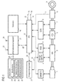
- FIG. 1 shows the drive train of a hybrid motor vehicle by an internal combustion engine 1 is driven, the internal combustion engine 1 is constructed conventionally and is therefore only shown schematically is.
- the internal combustion engine 1 is controlled by an electronic one Motor control (EMS) 2, which also controls the function electronic throttle valve control (ETC) can.
- EMS Electronic one Motor control
- ETC electronic throttle valve control
- the internal combustion engine 1 is on the output side Shaft with an electric motor in the form of an integrated Starter generator (ISG) 3 connected by the running Internal combustion engine 1 an energy storage device 4 can be loaded can.
- the energy store 4 is advantageous as an electrochemical Battery trained, but can also as Fuel cell, as a high-performance capacitor in the form of Ultra-Caps or a combination of different of these Storage technologies to be trained.
- the use of several Energy storage 4 is conceivable.
- ISG control unit ISG control unit
- a clutch not shown be arranged, which allows the internal combustion engine 1 from the drive train. This enables one Decoupling the speed of the integrated starter generator 3 from the internal combustion engine 1, which means the only waste energy generating braking effect of the internal combustion engine 1 switched off and the electrically usable braking effect of the Starter generator 3 is improved.
- a clutch 6 is arranged in the drive train, through which the internal combustion engine 1 and the integrated Starter generator 3 connected to a gear 7 or by this can be separated.
- the clutch 6 can, depending according to vehicle configuration, for example as a dry clutch or converter lockup clutch.
- the Coupling 6 and the transmission 7 are from an electronic Transmission control (EGS) 8 controlled, the electronic Transmission control 8 different gear ratios the gear 7 can adjust. Switching between the different gear ratios are used through the electronic transmission control 8 automatically a corresponding control of the clutch 6 and the actuators of the transmission 7, for. B. for the alley and gear positions Execution of the transmission 7 as an automated manual transmission.
- a gearbox with fixed gears can also be a gearbox with continuously adjustable transmission ratio be used. It is also immaterial whether the transmission 7 as a conventional automatic transmission with planetary gear set, as automated (automatic) Manual transmission or designed as a double clutch transmission is.
- the drive train is via a not shown Differentially connected to the wheels 9 of the motor vehicle. For reasons of clarity, the figure is an example only one wheel 9 is shown.
- a speed sensor 10 arranged, the ongoing the current speed N of the transmission output shaft or on comparable signal, such as wheel speed or vehicle speed, measures and via a line 11 to a cross-system Powertrain management (IPM) 12 transmitted.
- IPM Powertrain management
- Powertrain management receives additional input signals 12 inter alia via lines 13 and 14 signals which the Driver request regarding a drive torque or one Characterize braking torque. These signals can, for example by evaluating the positions of the accelerator pedal 15 or the brake pedal 16 can be obtained.
- Be further the powertrain management 12 further signals from symbolic sensors 18 combined into a block and possibly also data from the decentralized control devices 2, 5 and 8 fed.
- the data source 24 can be a short-range information source 27, e.g. in the form of a camera in conjunction with a Vision system or a radar system that is simple or are attached to the vehicle more than once.
- a short-range information source 26 is on the one hand it is possible to get vehicle-specific information about to get the route to be traveled. For example can be obstacles on the route, in the simplest case a vehicle in front can be recognized.
- On the other hand may receive information from data sources 24 and 25 not provided, incompletely or incorrectly have been meaningfully supplemented, corrected or replaced.
- the route data supplied by the data sources 25, 26 and 27 are managed by Information Management 21 as needed selected, combined, classified and / or compressed.
- the information management 21 additionally has an output interface 28 on, which allows optical or acoustic Transmit signals to the driver.
- the data source 24 can be provided in the vehicle (on board) but can also be wholly or partially outside the motor vehicle (off board). Is the data source 24 arranged at least partially outside the motor vehicle, the data becomes wireless, for example by radio transmission with the help of GSM or UMTS signals, to the information management 21 transferred. Can inside the motor vehicle the data both via lines, for example in the form of a Data bus system, as well as using wireless transmission technologies be transmitted.
- the powertrain management 12 sets depending on the supplied Signals the operating strategy in the form of target states of the drive train. Possible target states, such as for example “sailing”, “extended sailing”, “recuperative Braking "or” boosting "are, for example, from the older one Application WO 02/26520 A1 known and therefore at this point not described in detail. Thereby through the powertrain management 12 also the central operating parameters of the drive train, such as gear ratios and target torques for the drive units, but also Drive type and operating points defined. To implement the operating strategy, this information is the decentralized controls or control devices 2, 5 and 8 supplied in the form of control signals.
- the drive train management is via a bidirectional line 30 12 with an energy management 31 (EPM) - EPM doing so for Electrical Power Management - connected.
- the energy management 31 is in turn via a line 32 with the Energy storage 4 connected.
- the energy management 12 collects all information about the current and future electrical Energy requirements as well as current and future charge states of the electrical energy storage device 4.
- the state of the Energy storage is determined in a sub-function, which is often referred to as battery monitoring.
- This Function includes the transmission of data regarding optimal and maximum power and energy output as well as optimal and maximum power and energy consumption. additionally the energy management 31 controls the switching on and switching off all electrical auxiliary consumers in the motor vehicle, such as window heating, seat heating, wipers, lighting, Air conditioning and so on.
- the controls or control devices 2, 5 and 8 generate depending on these control signals control signals for the individual Powertrain aggregates or components.
- the Powertrain management 12, information management 21 and the energy management 31 are in FIG. 1 as independent Control units shown, but can also be whole or partially housed in a common control unit be or in one or more of the decentralized controls or Control devices 2, 5 or 8 can be integrated.
- the decentralized control devices 2, 5 and 8 as independent control units shown. These units too but can be combined in any way in one or several multifunctional control units become.
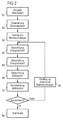
- a step S1 the driver or the destination Target position of the motor vehicle via the input interface 22 entered into the information management 21.
- the length of the section and thus the amount of data is preferably dependent on the current state of charge of the energy store 4 and / or of the storage capacity of the energy storage device 4.
- the route data for the next route section is requested.
- the length of the section and therefore the length Data volume again depends on the state of charge of the energy storage 4 at the time of the data request.
- energy management 31 depending on the transmitted energy demand value Kind of control plan for the electrical auxiliary consumers established.
- some Secondary consumers such as vehicle lighting or the windshield wipers are not switched off automatically by the system may be allowed, whereas other secondary consumers, such as for example the seat heating, for short-term energy savings can be put out of operation for a short time.
- the energy consumption of the electrical Ancillary consumers to the currently requested energy requirement be adjusted and thus the required energy requirement provided for as long as possible become.
- a step S7 the calculated period of time is sent to the energy management 31 reported back.
- the reported Time period from powertrain management 12 to implementation of optimal operating strategy for the specified route section Powertrain management recognizes it as insufficient 12 in an step S8 an alternative operating strategy set that results in lower energy requirements leads.
- the recalculated energy requirement (Step S4) is then transmitted to the energy management 31 again (Step S5) and from there a corresponding one Recalculated time period reported back (steps S6 and S7). This process is repeated until the reported one Time period from powertrain management 12 as sufficient is recognized.
- step S9 the powertrain management 12 a coordinated calculation performs the central operating parameters of the drive train and gear ratios and target torques for the drive units, but also the drive type and operating points sets.
- This information will be decentralized Controls or controls 2, 5 and 8 in Form of control signals supplied.
- the controls or control devices 2, 5 and 8 generate depending on these control signals Control signals for the individual units or components of the drive train.
- the energy management 31 determines that a lower or falls below the upper limit of the charge of the energy store 4 or is exceeded, a corresponding one Request signal to the powertrain management 12 transmitted.
- the powertrain management 12 can then this information depending on the priority of the request signal either when defining the operating strategy for take into account the next section of the route or immediately the current operating strategy for the moment change the route section to be completed so that the energy storage is charged or discharged as soon as possible becomes.
- Is information management 21 a current change in Route data already transmitted - for example a reported one Traffic jam, a short-term diversion on the route or an unforeseen change in the condition of the road, for example by rain - recognized the updated data is not required for the powertrain management 12 transmitted. Depending on the updated Data then becomes one based on the changed environmental conditions adjusted new operating strategy and go through steps S4 to S9 accordingly.
Abstract
Description
Die Erfindung betrifft ein Verfahren zum Steuern des Antriebsstrangs eines Hybridfahrzeugs.The invention relates to a method for controlling the drive train of a hybrid vehicle.
Zukünftige Fahrzeuggenerationen werden zunehmend mit Hybridantrieben ausgestattet sein. Hybridantriebe weisen neben dem herkömmlichen Verbrennungsmotor ein zusätzliches Antriebsaggregat auf. Dieses zusätzliche Antriebsaggregat ist häufig als Elektromotor ausgeführt, der über einen wieder aufladbaren Energiespeicher, zum Beispiel eine Batterie, mit Energie versorgt wird. Hybridantriebe weisen im Vergleich zu herkömmlichen Antrieben eine Vielzahl zusätzlicher Betriebszustände des Antriebsstrangs auf. Neben einem rein verbrennungsmotorischen Betrieb sind auch ein rein elektromotorischer Betrieb und ein kombinierter Betrieb möglich. Des Weiteren kann zwischen Betriebszuständen mit und ohne Ladung der Batterie unterschieden werden.Future generations of vehicles will increasingly be equipped with hybrid drives be equipped. Hybrid drives have in addition to conventional internal combustion engine an additional drive unit on. This additional drive unit is common designed as an electric motor that has a rechargeable Energy storage, for example a battery, with energy is supplied. Hybrid drives have compared to conventional ones Drives a variety of additional operating states of the drive train. In addition to a purely internal combustion engine Operation is also a purely electric motor operation and a combined operation possible. Furthermore, between Operating states with and without charging the battery differentiated become.
Um die in einem Hybridfahrzeug gespeicherte Energie - im flüssigen Kraftstoff und in dem Energiespeicher - möglichst effizient zu nutzen und somit eine Überdimensionierung einzelner Komponenten des Antriebsstrangs zu vermeiden, werden hohe Anforderungen an die Steuerung des Antriebsstrangs gestellt. Abhängig vom Betriebszustand des Antriebsstrangs werden dem Kraftstoff und dem Energiespeicher unterschiedliche Energiemengen entnommen oder unterschiedliche Energiemengen in den Energiespeicher eingespeist. Bei der Steuerung ist insbesondere zu berücksichtigen, dass der Streckenverlauf der zukünftig zu absolvierenden Fahrstrecke entscheidenden Einfluss auf die benötigte oder rückzugewinnende Energiemenge hat.To the energy stored in a hybrid vehicle - in liquid fuel and in the energy storage - if possible to use efficiently and thus oversizing individual Avoid powertrain components high demands are placed on the control of the drive train. Depending on the operating state of the drive train the fuel and the energy storage different Amounts of energy taken or different amounts of energy fed into the energy storage. When it comes to control in particular to take into account that the route of the decisive influence in the future on the required or recoverable amount of energy Has.
Zukünftige Fahrzeuggenerationen werden häufig mit einem Navigationssystem oder ähnlichen Komponenten ausgestattet sein, die eine Vorausschau auf den Streckenverlauf der zukünftig zu absolvierenden Fahrstrecke und somit eine Abschätzung des zu erwartenden Energiebedarfs ermöglichen.Future vehicle generations will often be equipped with a navigation system or similar components, which provide a foresight on the route of the future completed route and thus an estimate of the enable expected energy requirements.
Aus der DE 198 31 487 C1 ist ein Verfahren zum Betrieb eines eine Batterie aufweisenden Hybridantriebes eines Kraftfahrzeuges bekannt, bei dem Informationen bezüglich einer zu absolvierenden Fahrstrecke erfasst werden. Unter Berücksichtigung dieser Informationen werden dann zu erwartende Leistungsanforderungen an den Hybridantrieb über den Verlauf der Fahrstrecke berechnet und abhängig von den berechneten Leistungsanforderungen und unter Berücksichtigung der Wirkungsgrade der Antriebskomponenten oder Betriebsarten wird schließlich ein Zeitplan ermittelt, der die Steuerung der einzelnen Antriebskomponenten oder Betriebsarten steuert.DE 198 31 487 C1 describes a method for operating a a hybrid drive of a motor vehicle having a battery known, where information regarding a course to be completed Travel distance are recorded. Considering this information then becomes expected performance requirements to the hybrid drive over the course of the Travel distance calculated and depending on the calculated performance requirements and taking into account the efficiencies the drive components or operating modes Finally, a schedule is established that will control the controls individual drive components or operating modes.
Aufgabe der Erfindung ist es daher, unter Berücksichtigung der Fahrsituation und der Fahrstrecke eine bezüglich des Energiebedarfs möglichst optimale Steuerung für den Antriebsstrang eines Hybridfahrzeugs zu schaffen.The object of the invention is therefore, taking into account the driving situation and the driving distance in terms of energy requirements optimal control for the drive train to create a hybrid vehicle.
Diese Aufgabe wird durch ein Verfahren mit den Merkmalen des
Patentsanspruchs 1 gelöst. Vorteilhafte Weiterbildungen der
Erfindung sind in den Unteransprüchen niedergelegt.This task is accomplished by a process with the characteristics of
Erfindungsgemäß werden zunächst Daten, die zumindest einen Teilabschnitt der zukünftig zu absolvierenden Fahrstrecke charakterisieren, angefordert. Abhängig von diesen Daten wird eine Betriebsstrategie für die einzelnen Komponenten des Antriebsstrangs festgelegt. Abhängig von der Betriebsstrategie und von den Streckendaten wird ein zu erwartender Energieverbrauch berechnet. Anschließend wird eine Zeitspanne berechnet, für die die berechnete Energie zur Verfügung gestellt werden kann. Wird die berechnete Zeitspanne als ausreichend erkannt, so werden die einzelnen Komponenten des Antriebsstrangs gemäß der Betriebsstrategie gesteuert. Wird die berechnete Zeitspanne dagegen als nicht ausreichend erkannt, so wird eine alternative Betriebsstrategie festgelegt und die sich daraus ergebenden Zeitspanne erneut geprüft.According to the invention, data that is at least one Part of the route to be completed in the future characterize, requested. Depends on this data an operating strategy for the individual components of the drive train established. Depending on the operating strategy and from the route data is an expected energy consumption calculated. Then a period of time is calculated for which the calculated energy is made available can be. The calculated period of time is considered sufficient the individual components of the drive train are recognized controlled according to the operating strategy. Will the on the other hand, the calculated period of time was not recognized as sufficient, an alternative operating strategy is determined and the resulting time period checked again.
Ein Ausführungsbeispiel der Erfindung wird im folgenden anhand der Figuren erläutert. Es zeigen:
Figur 1- eine schematische Darstellung eines Antriebsstrangs eines Hybridfahrzeugs und
Figur 2- ein Flussdiagramm eines erfindungsgemäßen Verfahrens
zum Steuern eines Antriebsstrangs gemäß
Figur 1.
- Figure 1
- a schematic representation of a drive train of a hybrid vehicle and
- Figure 2
- 2 shows a flowchart of a method according to the invention for controlling a drive train according to FIG. 1.
Die in Figur 1 dargestellte Anordnung zeigt den Antriebsstrang
eines hybriden Kraftfahrzeuges, der von einem Verbrennungsmotor
1 angetrieben wird, wobei der Verbrennungsmotor 1
herkömmlich aufgebaut ist und deshalb nur schematisch dargestellt
ist. Der Verbrennungsmotor 1 wird durch eine elektronische
Motorsteuerung (EMS) 2 gesteuert, die auch die Funktion
einer elektronischen Drosselklappenregelung (ETC) übernehmen
kann. Ausgangsseitig ist der Verbrennungsmotor 1 über eine
Welle mit einem Elektromotor in Form eines integrierten
Startergenerators (ISG) 3 verbunden, durch den bei laufendem
Verbrennungsmotor 1 ein Energiespeicher 4 geladen werden
kann. Der Energiespeicher 4 ist dabei vorteilhaft als elektrochemische
Batterie ausgebildet, kann aber ebenso als
Brennstoffzelle, als Hochleistungs-Kondensator in Form von
Ultra-Caps oder als Kombination aus verschiedenen dieser
Speichertechnologien ausgebildet sein. Auch der Einsatz mehrerer
Energiespeicher 4 ist denkbar. Bei stillstehendem
Verbrennungsmotor 1 kann der integrierte Startergenerator 3
auch zum Anlassen des Verbrennungsmotors 1 verwendet werden.
Der integrierte Startergenerator 3 ist dabei vorzugsweise als
Asynchronmaschine ausgebildet, kann aber auch als Synchronmaschine
oder Gleichstrommotor ausgebildet sein. Gesteuert wird
der integrierte Startergenerator 3 durch eine ISG-Steuereinheit
(ISGS) 5. The arrangement shown in Figure 1 shows the drive train
of a hybrid motor vehicle by an
Vorteilhaft kann zwischen dem Verbrennungsmotor 1 und dem integrierten
Startergenerator 3 eine nicht dargestellte Kupplung
angeordnet sein, die es ermöglicht, den Verbrennungsmotor
1 von dem Antriebsstrang abzutrennen. Dies ermöglicht eine
Entkopplung der Drehzahl des integrierten Startergenerators
3 von dem Verbrennungsmotor 1, wodurch die nur Verlustenergie
erzeugende Bremswirkung des Verbrennungsmotor 1 ausgeschaltet
wird und die elektrisch nutzbare Bremswirkung des
Startergenerators 3 verbessert wird.Can advantageously between the
Weiterhin ist in dem Antriebsstrang eine Kupplung 6 angeordnet,
durch die der Verbrennungsmotor 1 und der integrierte
Startergenerator 3 mit einem Getriebe 7 verbunden oder von
diesem getrennt werden kann. Die Kupplung 6 kann dabei, je
nach Fahrzeugkonfiguration, beispielsweise als Trockenkupplung
oder Wandlerüberbrückungskupplung ausgeführt sein. Die
Kupplung 6 und das Getriebe 7 werden von einer elektronischen
Getriebesteuerung (EGS) 8 angesteuert, wobei die elektronische
Getriebesteuerung 8 verschiedene Übersetzungsverhältnisse
des Getriebes 7 einstellen kann. Die Umschaltung zwischen
den verschiedenen Übersetzungsverhältnissen erfolgt hierbei
durch die elektronische Getriebesteuerung 8 automatisch durch
eine entsprechende Regelung der Kupplung 6 und der Aktuatoren
des Getriebes 7, z. B. für die Gassen- und Gangstellungen bei
Ausführung des Getriebes 7 als automatisiertes Handschaltgetriebe.
Alternativ zu einem Getriebe mit festen Gangstufen
kann auch ein Getriebe mit kontinuierlich einstellbarem Übersetzungsverhältnis
verwendet werden. Ebenso ist es unwesentlich,
ob das Getriebe 7 als konventionelles Automatikgetriebe
mit Planetenradsatz, als automatisiertes (automatisches)
Handschaltgetriebe oder als Doppelkupplungsgetriebe ausgeführt
ist.Furthermore, a
Ferner ist der Antriebsstrang über ein nicht dargestelltes
Differential mit den Rädern 9 des Kraftfahrzeugs verbunden.
Aus Gründen der Übersichtlichkeit ist in der Figur beispielhaft
nur ein Rad 9 dargestellt. Schließlich ist in dem Antriebsstrang
ein Drehzahlsensor 10 angeordnet, der laufend
die aktuelle Drehzahl N der Getriebeausgangswelle oder ein
vergleichbares Signal, wie Raddrehzahl oder Fahrzeuggeschwindigkeit,
misst und über eine Leitung 11 an ein systemübergreifendes
Antriebsstrangmanagement (IPM) 12 übermittelt. Als
weitere Eingangssignale erhält das Antriebsstrangmanagement
12 unter anderem über Leitungen 13 und 14 Signale, die den
Fahrerwunsch bezüglich eines Antriebsmoments bzw. eines
Bremsmoments charakterisieren. Diese Signale können beispielsweise
durch Auswertung der Stellungen des Fahrpedals 15
bzw. des Bremspedals 16 gewonnen werden. Des weiteren werden
dem Antriebsstrangmanagement 12 weitere Signale von symbolisch
zu einem Block zusammengefassten Sensoren 18 und eventuell
auch Daten aus den dezentralen Steuereinrichtungen 2, 5
und 8 zugeführt.Furthermore, the drive train is via a not shown
Differentially connected to the
Über eine Leitung 20 werden dem Antriebsstrangmanagement 12
auch Daten über die zukünftig zu absolvierende Fahrstrecke
von einem Informationsmanagement 21 zur Verfügung gestellt.
Hierzu weist das Informationsmanagement 21 eine Eingabeschnittstelle
22 zur Eingabe des Fahrziels oder der Zielposition
des Kraftfahrzeugs durch den Fahrer auf. Das Informationsmanagement
21 ist über eine Datenschnittstelle 23 mit einer
Datenquelle 24 verbunden. Die Datenquelle 24 weist eine
digitalisierte Straßenkarte 25 auf. Der Begriff "Straßenkarte"
soll dabei aber nicht einschränkend wirken. Neben Informationen
über den bloßen Richtungsverlauf von Straßen kann
die digitalisierte Straßenkarte beliebige Zusatzinformationen
über die zu befahrenden Straßen oder Wege beinhalten. Die
verfügbaren Streckeninformationen lassen sich dabei in drei
Kategorien einteilen:
Neben der Straßenkarte 25 weist die Datenquelle 24 vorteilhaft eine Verkehrinformationsquelle 26 auf, die die aktuellen Werte variabler Größen bezüglich der zu absolvierenden Fahrstrecke zur Verfügung stellt. Beispielhaft sind dabei folgende Informationen denkbar:
- Informationen über den Verkehrfluss (z.B. aktuelle Staumeldungen),
- Informationen über aktuell auftretende Änderungen der Straßenbeschaffenheit (z.B. Glatteis),
- Informationen über aktuelle oder zu erwartende, zum Beispiel die Sicht betreffende Witterungseinflüsse (Niederschläge, Nebel, Wettervorhersage),
- Informationen über den aktuellen Funktionszustand von Anlagen zur Verkehrsregelung (z.B. aktuelle Ampelphase),
- Informationen über außerordentliche Verkehrsreglementierungen (z.B. vorübergehend gesperrte Straßen oder umweltbedingte Vorschriften bezüglich eines emissionsarmen Betriebs) .
- Information about the traffic flow (e.g. current traffic jam reports),
- Information about currently occurring changes in road conditions (e.g. black ice),
- Information about current or expected weather influences (precipitation, fog, weather forecast), for example the view,
- Information about the current functional status of traffic control systems (e.g. current traffic light phase),
- Information about extraordinary traffic regulations (e.g. temporarily closed roads or environmental regulations regarding low-emission operations).
Zudem kann die Datenquelle 24 eine Nahbereichs-Informationsquelle
27, z.B. in Form einer Kamera in Verbindung mit einem
Bildverarbeitungssystem oder eines Radarsystems, die einfach
oder mehrfach am Fahrzeug angebracht sind, aufweisen. Mit
Hilfe einer derartigen Nahbereichs-Informationsquelle 26 ist
es zum einen möglich, fahrzeugspezifische Informationen über
die zu befahrende Fahrstrecke zu erlangen. Beispielsweise
können Hindernisse auf der Fahrstrecke, im einfachsten Fall
ein vorausfahrendes Fahrzeug, erkannt werden. Zum anderen
können Informationen, die von den Datenquellen 24 und 25
nicht, unvollständig oder fehlerhaft zur Verfügung gestellt
wurden, sinnvoll ergänzt, berichtigt oder ersetzt werden.In addition, the
Die von den Datenquellen 25, 26 und 27 gelieferten Streckendaten
werden vom Informationsmanagement 21 je nach Bedarf
ausgewählt, kombiniert, klassifiziert und/oder komprimiert.
Das Informationsmanagement 21 weist zusätzlich eine Ausgabeschnittstelle
28 auf, die es ermöglicht, optische oder akustische
Signale an den Fahrer zu übermitteln.The route data supplied by the data sources 25, 26 and 27
are managed by
Außerdem wird durch das Informationsmanagement 21 die aktuelle Fahrzeugposition bestimmt. Zur Ermittlung einer möglichst genauen Fahrzeugposition wird beispielsweise eines der folgenden Verfahren, auch in Kombination, angewendet:
- Positionsbestimmung über GPS (Global Positioning System, Satellitenortung),
- Koppelnavigation aus aktuellen Zustandsdaten des Fahrzeugs (Gierwinkel und Fahrzeuggeschwindigkeit),
- Differentielle Radsensordaten,
- Kompassdaten und/oder
- verschiedene Map-Matching Algorithmen.
- Position determination via GPS (Global Positioning System, satellite positioning),
- Dead reckoning from current vehicle status data (yaw angle and vehicle speed),
- Differential wheel sensor data,
- Compass data and / or
- different map matching algorithms.
Die Datenquelle 24 kann im Fahrzeug (on board) vorgesehen
sein, kann aber auch ganz oder teilweise außerhalb des Kraftfahrzeugs
(off board) angeordnet sein. Ist die Datenquelle 24
zumindest teilweise außerhalb des Kraftfahrzeugs angeordnet,
werden die Daten drahtlos, zum Beispiel durch Funkübertragung
mit Hilfe von GSM- oder UMTS-Signalen, an das Informationsmanagement
21 übertragen. Innerhalb des Kraftfahrzeugs können
die Daten sowohl über Leitungen, zum Beispiel in Form eines
Datenbus-Systems, als auch mittels drahtlosen Übertragungstechniken
übertragen werden.The
Das Antriebsstrangmanagement 12 legt abhängig von den zugeführten
Signalen die Betriebsstrategie in Form von Sollzuständen
des Antriebsstrangs fest. Mögliche Sollzustände, wie
zum Beispiel "Segeln", "erweitertes Segeln", "rekuperatives
Bremsen" oder "Boosten", sind beispielsweise aus der älteren
Anmeldung WO 02/26520 A1 bekannt und daher an dieser Stelle
nicht im Einzelnen beschrieben. Dabei werden durch das Antriebsstrangmanagement
12 auch die zentralen Betriebsparameter
des Antriebsstrangs, wie zum Beispiel Getriebeübersetzungen
und Soll-Drehmomente für die Antriebsaggregate, aber auch
Antriebsart und Betriebspunkte festgelegt. Zur Umsetzung der
festgelegten Betriebsstrategie werden diese Informationen den
dezentralen Steuerungen oder Steuereinrichtungen 2, 5 und 8
in Form von Steuersignalen zugeführt.The
Über eine bidirektionale Leitung 30 ist das Antriebsstrangmanagement
12 mit einem Energiemanagement 31 (EPM) - EPM steht
dabei für Electrical Power Management - verbunden. Das Energiemanagement
31 ist seinerseits über eine Leitung 32 mit dem
Energiespeicher 4 verbunden. Das Energiemanagement 12 sammelt
alle Informationen über den aktuellen und zukünftigen elektrischen
Energiebedarf sowie aktuelle und zukünftige Ladezustände
des elektrischen Energiespeichers 4. Der Zustand des
Energiespeichers wird dabei in einer Unterfunktion ermittelt,
die häufig als Batterie-Monitoring bezeichnet wird. Diese
Funktion beinhaltet die Übermittlung von Daten bezüglich optimaler
und maximaler Leistungs- und Energieabgabe sowie optimaler
und maximaler Leistungs- und Energieaufnahme. Zusätzlich
steuert das Energiemanagement 31 das Zuschalten und Abschalten
aller elektrischen Nebenverbraucher im Kraftfahrzeug,
wie Scheibenheizung, Sitzheizung, Scheibenwischer, Beleuchtung,
Klimaanlage und so weiter.The drive train management is via a
Die Steuerungen oder Steuereinrichtungen 2, 5 und 8 erzeugen
abhängig von diesen Steuersignalen Stellsignale für die einzelnen
Aggregate oder Komponenten des Antriebsstrangs. Das
Antriebsstrangmanagement 12, das Informationsmanagement 21
und das Energiemanagement 31 sind in Figur 1 als eigenständige
Steuereinheiten dargestellt, können aber ebenso ganz oder
teilweise in einer gemeinsamen Steuereinheit untergebracht
sein oder in eine oder mehrere der dezentralen Steuerungen oder
Steuereinrichtungen 2, 5 oder 8 integriert sein. Ebenso
sind auch die dezentralen Steuereinrichtungen 2, 5 und 8 als
eigenständige Steuereinheiten dargestellt. Auch diese Einheiten
können aber in beliebiger Art und Weise kombiniert in einem
oder mehreren multifunktionalen Steuergeräten untergebracht
werden.The controls or
Im Folgenden wird anhand der Figur 2 das erfindungsgemäße Steuerverfahren für den Antriebsstrang eines Hybridfahrzeugs erläutert:In the following, the invention according to FIG Control method for the drive train of a hybrid vehicle explains:
In einem Schritt S1 wird vom Fahrer das Fahrziel oder die
Zielposition des Kraftfahrzeugs über die Eingabeschnittstelle
22 in das Informationsmanagement 21 eingegeben. Auf ein Anforderungssignal
des Antriebsstrangmanagements 12 hin übermittelt
das Informationsmanagement 21 in einem Schritt S2
Streckendaten über die zukünftig zu absolvierende Fahrstrecke
an das Antriebsstrangmanagement 12. In einer bevorzugten Ausführungsform
werden dabei lediglich Daten bezüglich einer
Teilstrecke der zu absolvierenden Fahrstrecke angefordert und
übermittelt. Die Länge der Teilstrecke und somit die Datenmenge
ist dabei vorzugsweise abhängig vom aktuellen Ladezustand
des Energiespeichers 4 und/oder von der Speicherkapazität
des Energiespeichers 4. Am Ende oder kurz vor dem Ende
der Teilstrecke werden dann vom Antriebsstrangmanagement 12
die Streckendaten für den nächsten Streckenabschnitt angefordert.
Auch dabei ist die Länge der Teilstrecke und somit die
Datenmenge wieder abhängig vom Ladezustand des Energiespeichers
4 zum Zeitpunkt der Datenanforderung.In a step S1, the driver or the destination
Target position of the motor vehicle via the
Abhängig von den übermittelten Streckendaten für den angeforderten Streckenabschnitt und von den übrigen Eingangssignalen, die die aktuelle Fahrsituation charakterisieren, legt das Antriebsstrangmanagement 12 in einem Schritt S3 eine bezüglich eines Gütefunktionals aus Gesamtwirkungsgrad, Gesamtenergieverbrauch und Gesamtemission optimale Betriebsstrategie für diesen Streckenabschnitt fest. Dabei werden im wesentlichen folgende Betriebsparameter und Systemgrößen bestimmt:
- Sollzustände des Antriebsstrangs - inklusive der notwendigen Ein- und Ausschaltzeitpunkte für den Verbrennungsmotor und der Leistungsaufteilung zwischen Verbrennungsmotor, Elektromotor und Energiespeicher
- Getriebeübersetzung - hat Auswirkungen auf die Wirkungsgrade von Verbrennungsmotor und Elektromotor
- Sollgeschwindigkeitsprofil - dabei werden alle Streckendaten berücksichtigt, die die voraussichtliche Fahrgeschwindigkeit beeinflussen, zum Beispiel Geschwindigkeitsbeschränkungen, Stop-Schilder, Ortsdurchfahrten, Staumeldungen, Kurven, nasse Fahrbahn oder Glatteis
- Leistung zur Überwindung des Luftwiderstands des Kraftfahrzeugs,
- Leistung zur Überwindung des Rollwiderstands des Kraftfahrzeugs (Reibleistung),
- Leistung zu Überwindung des Steigungswiderstands,
- Leistung für die positive oder negative Fahrzeugbeschleunigung
- Target states of the drive train - including the necessary switch-on and switch-off times for the internal combustion engine and the power distribution between internal combustion engine, electric motor and energy storage
- Gear ratio - has an impact on the efficiency of the internal combustion engine and electric motor
- Target speed profile - all route data that influence the anticipated driving speed are taken into account, for example speed restrictions, stop signs, passage through town, traffic jams, bends, wet roads or black ice
- Power to overcome the air resistance of the motor vehicle,
- Power to overcome the rolling resistance of the motor vehicle (friction),
- Power to overcome the gradient resistance,
- Performance for positive or negative vehicle acceleration
Der berechnete Energiebedarfswert wird dann in einem Schritt S5 von dem Antriebsstrangmanagement 12 über die Leitung 30 an das Energiemanagement 31 übermittelt. Vom Energiemanagement 31 wird daraufhin in einem Schritt S6 eine Zeitspanne berechnet, für die der geforderte Energiebedarf zur Verfügung gestellt werden kann. Dabei wird auch der voraussichtliche Energiebedarf für elektrische Nebenverbraucher berücksichtigt. So wird beispielsweise der Energieverbrauch folgender Komponenten berücksichtigt:
- Fahrzeugbeleuchtung bei Dunkelheit, Nebel oder in einem Tunnel
- Klimaanlage bei starker Sonneneinstrahlung
- Heizung bei niedriger Außentemperatur
- elektrische Lenkung oder elektrische Bremse bei Kurven
- aktive Dämpfung bei schlechtem Straßenzustand
- Vehicle lighting in the dark, fog or in a tunnel
- Air conditioning in strong sunlight
- Heating when the outside temperature is low
- electric steering or electric brake when cornering
- active damping in poor road conditions
In einer bevorzugten Ausführungsform wird vom Energiemanagement
31 abhängig vom übermittelten Energiebedarfswert eine
Art Steuerungsplan für die elektrischen Nebenverbraucher
festgelegt. Dabei wird insbesondere berücksichtigt, dass einige
Nebenverbraucher, wie beispielsweise Fahrzeugbeleuchtung
oder Scheibenwischer vom System nicht selbständig abgeschaltet
werden dürfen, wohingegen andere Nebenverbraucher, wie
zum Beispiel die Sitzheizung, zur kurzfristigen Energieeinsparung
durchaus kurzzeitig außer Betrieb gesetzt werden können.
Auf diese Weise kann der Energieverbrauch der elektrischen
Nebenverbraucher an den aktuell angeforderten Energiebedarf
angepasst werden und somit der geforderte Energiebedarf
für eine möglichst lange Zeitspanne zur Verfügung gestellt
werden. In a preferred embodiment,
In einem Schritt S7 wird die berechnete Zeitspanne an das Energiemanagement
31 zurückgemeldet. Wird die zurückgemeldete
Zeitspanne vom Antriebsstrangmanagement 12 zur Umsetzung der
optimalen Betriebsstrategie für den vorgegebenen Streckenabschnitt
als nicht ausreichend erkannt, so wird vom Antriebsstrangmanagement
12 in einem Schritt S8 eine alternative Betriebsstrategie
festgelegt, die zu einem geringeren Energiebedarf
führt. Der darauf hin neu berechnete Energiebedarf
(Schritt S4) wird dann erneut an das Energiemanagement 31 übertragen
(Schritt S5) und von dort wird eine entsprechende
neuberechnete Zeitspanne zurückgemeldet (Schritte S6 und S7).
Dieser Vorgang wird solange wiederholt, bis die zurückgemeldete
Zeitspanne vom Antriebsstrangmanagement 12 als ausreichend
erkannt wird.In a step S7, the calculated period of time is sent to the
Ist auf diese Weise eine realisierbare Betriebsstrategie gefunden,
wird diese in einem Schritt S9 derart umgesetzt, dass
das Antriebsstrangmanagement 12 eine koordinierte Berechnung
der zentralen Betriebsparameter des Antriebsstrangs durchführt
und dabei Getriebeübersetzungen und Soll-Drehmomente
für die Antriebsaggregate, aber auch Antriebsart und Betriebspunkte
festlegt. Diese Informationen werden den dezentralen
Steuerungen oder Steuereinrichtungen 2, 5 und 8 in
Form von Steuersignalen zugeführt. Die Steuerungen oder Steuereinrichtungen
2, 5 und 8 erzeugen abhängig von diesen Steuersignalen
Stellsignale für die einzelnen Aggregate oder Komponenten
des Antriebsstrangs.If a feasible operating strategy is found in this way,
is implemented in a step S9 such that
the powertrain management 12 a coordinated calculation
performs the central operating parameters of the drive train
and gear ratios and target torques
for the drive units, but also the drive type and operating points
sets. This information will be decentralized
Controls or controls 2, 5 and 8 in
Form of control signals supplied. The controls or
Wird vom Energiemanagement 31 festgestellt, dass ein unterer
oder oberer Grenzwert der Ladung des Energiespeichers 4 unterschritten
beziehungsweise überschritten ist, wird ein entsprechendes
Anforderungssignal an das Antriebsstrangmanagement
12 übermittelt. Das Antriebsstrangmanagement 12 kann
dann je nach Priorität des Anforderungssignals diese Information
entweder bei der Festlegung der Betriebsstrategie für
den nächstfolgenden Streckenabschnitt berücksichtigen oder
unmittelbar die aktuelle Betriebsstrategie für den momentan
zu absolvierenden Streckenabschnitt dahin gehend ändern, dass
der Energiespeicher möglichst umgehend geladen oder entladen
wird.If the
Wird vom Informationsmanagement 21 eine aktuelle Änderung der
bereits übermittelten Streckendaten - zum Beispiel ein gemeldeter
Stau, eine kurzfristige Umleitung auf der Fahrstrecke
oder eine unvorhergesehen eingetretene Veränderung der Fahrbahnbeschaffenheit,
beispielsweise durch Regen - erkannt,
werden die aktualisierten Daten ohne Anforderung an das Antriebsstrangmanagement
12 übermittelt. Abhängig von den aktualisierten
Daten wird dann eine an die veränderten Umgebungsbedingungen
angepasste neue Betriebsstrategie festgelegt und
die Schritte S4 bis S9 entsprechend durchlaufen.Is information management 21 a current change in
Route data already transmitted - for example a reported one
Traffic jam, a short-term diversion on the route
or an unforeseen change in the condition of the road,
for example by rain - recognized
the updated data is not required for the
Claims (5)
Applications Claiming Priority (2)
| Application Number | Priority Date | Filing Date | Title |
|---|---|---|---|
| DE10128260 | 2001-06-11 | ||
| DE10128260 | 2001-06-11 |
Publications (3)
| Publication Number | Publication Date |
|---|---|
| EP1270303A2 true EP1270303A2 (en) | 2003-01-02 |
| EP1270303A3 EP1270303A3 (en) | 2006-03-01 |
| EP1270303B1 EP1270303B1 (en) | 2007-07-11 |
Family
ID=7687896
Family Applications (1)
| Application Number | Title | Priority Date | Filing Date |
|---|---|---|---|
| EP02100523A Expired - Fee Related EP1270303B1 (en) | 2001-06-11 | 2002-05-21 | Method for controlling the power train of a hybrid vehicle |
Country Status (3)
| Country | Link |
|---|---|
| US (1) | US6687607B2 (en) |
| EP (1) | EP1270303B1 (en) |
| DE (1) | DE50210441D1 (en) |
Cited By (32)
| Publication number | Priority date | Publication date | Assignee | Title |
|---|---|---|---|---|
| DE102006062584A1 (en) * | 2006-12-29 | 2008-07-10 | Clean Mobile Gmbh | Vehicle e.g. passenger car, drive unit, has computation unit computing route which can be traveled on by vehicle, where drive unit stores electric power in battery while driving vehicle depending on computed route |
| DE102007008694A1 (en) * | 2007-02-20 | 2008-08-21 | Deutsche Post Ag | Logistics vehicle with hybrid drive |
| WO2008113836A1 (en) | 2007-03-20 | 2008-09-25 | Continental Teves Ag & Co. Ohg | Method and device for predictive control and/or regulation of a hybrid drive in a motor vehicle and hybrid vehicle |
| DE102007053279A1 (en) * | 2007-11-08 | 2009-05-20 | Robert Bosch Gmbh | Two drive systems controlling method for vehicle i.e. hybrid vehicle, involves controlling drive systems depending on data, which are detected by air quality sensor and/or video camera and/or communication system |
| FR2927042A1 (en) * | 2008-02-04 | 2009-08-07 | Renault Sas | Hybrid propulsion i.e. power train, control method for hybrid vehicle, involves stopping and releasing stop of thermal engine part based on speed information, slope information and electric energy information available from battery |
| WO2009106852A1 (en) * | 2008-02-29 | 2009-09-03 | Ricardo Uk Limited | A method of controlling vehicle speed change |
| WO2009156217A1 (en) * | 2008-06-23 | 2009-12-30 | Robert Bosch Gmbh | Method for calculating a journey route, method for controlling a drive mechanism, and apparatus |
| WO2010012778A1 (en) * | 2008-07-31 | 2010-02-04 | Continental Automotive Gmbh | Method and device for operating a motor vehicle |
| WO2010054727A1 (en) * | 2008-11-12 | 2010-05-20 | Bayerische Motoren Werke Aktiengesellschaft | Method for operating a hybrid drive |
| WO2010079022A1 (en) * | 2009-01-07 | 2010-07-15 | Robert Bosch Gmbh | Method for energy efficient charging of a vehicle battery |
| DE102009046341A1 (en) * | 2009-11-03 | 2011-05-05 | Zf Friedrichshafen Ag | Method for controlling a rolling or sailing function of a vehicle |
| WO2011033529A3 (en) * | 2009-09-15 | 2011-05-26 | Kpit Cummins Infosystems Ltd. | Method of providing assistance for a hybrid vehicle based on user input |
| DE102010008019A1 (en) * | 2010-02-08 | 2011-08-11 | Dr. Ing. h.c. F. Porsche Aktiengesellschaft, 70435 | Method and device for determining a boost control strategy of a hybrid vehicle drive |
| WO2011128410A1 (en) * | 2010-04-16 | 2011-10-20 | Continental Automotive Gmbh | Method and apparatus for drive control for a hybrid vehicle |
| WO2011134992A1 (en) * | 2010-04-29 | 2011-11-03 | Avl List Gmbh | Method for operating an electric vehicle |
| CN102470910A (en) * | 2009-08-10 | 2012-05-23 | 罗伯特·博世有限公司 | Power management system for a vehicle having combined electric and muscle power drive and method for operating such a vehicle |
| WO2012069533A1 (en) * | 2010-11-25 | 2012-05-31 | Continental Automotive Gmbh | Method and device for controlling the drive of a hybrid vehicle |
| WO2012150113A1 (en) * | 2011-05-04 | 2012-11-08 | Bayerische Motoren Werke Aktiengesellschaft | Method for operating a hybrid drive |
| DE102011116184A1 (en) * | 2011-10-14 | 2013-04-18 | Volkswagen Aktiengesellschaft | Method for operating e.g. electric car, involves determining power requirement of auxiliary equipments of vehicle, and determining driving mode for vehicle based on power requirement, where driving mode influences estimated travel time |
| US8784267B2 (en) | 2009-11-03 | 2014-07-22 | Zf Friedrichshafen Ag | Method for controlling a rolling or coasting function of a vehicle |
| DE102013020759A1 (en) * | 2013-12-09 | 2015-06-11 | Audi Ag | Method and device for controlling a hybrid drive in a vehicle |
| DE102013225558A1 (en) | 2013-12-11 | 2015-06-11 | Volkswagen Aktiengesellschaft | Method for determining a driving state of a hybrid vehicle for route segments of a preceding route and hybrid vehicle |
| WO2016041661A1 (en) * | 2014-09-16 | 2016-03-24 | Robert Bosch Gmbh | Control device and method for the predictive, consumption-optimised operation of a hybrid vehicle |
| US9744873B2 (en) | 2011-10-12 | 2017-08-29 | Volkswagen Ag | Method and control device for charging a battery of a vehicle |
| DE102008063088B4 (en) * | 2008-12-24 | 2017-09-07 | Eberspächer Climate Control Systems GmbH & Co. KG | Operating method of a fuel cell system arranged in a vehicle |
| DE112006002061B4 (en) * | 2005-08-11 | 2017-10-19 | Toyota Jidosha Kabushiki Kaisha | Mobile body including a power generation device |
| US9884615B2 (en) | 2009-09-15 | 2018-02-06 | Kpit Technologies Limited | Motor assistance for a hybrid vehicle based on predicted driving range |
| DE102017204607A1 (en) | 2017-03-20 | 2018-09-20 | Bayerische Motoren Werke Aktiengesellschaft | Automatic and individual adaptation of consumption information |
| DE102018209434A1 (en) * | 2018-06-13 | 2019-12-19 | Audi Ag | Method for operating a fuel cell device assigned to a motor vehicle and motor vehicle with a fuel cell device |
| US10525965B2 (en) | 2014-08-19 | 2020-01-07 | Audi Ag | Method for predicting the consumption of a motor vehicle, motor vehicle and computer program |
| DE102019129706A1 (en) * | 2019-11-05 | 2021-05-20 | Bayerische Motoren Werke Aktiengesellschaft | Control method for optimizing the operating strategy for hybrid vehicles with a high degree of electrification |
| EP3974268A1 (en) * | 2020-09-23 | 2022-03-30 | Toyota Jidosha Kabushiki Kaisha | Control system for and control method of hybrid vehicle |
Families Citing this family (39)
| Publication number | Priority date | Publication date | Assignee | Title |
|---|---|---|---|---|
| JP3896973B2 (en) * | 2003-02-25 | 2007-03-22 | 株式会社デンソー | Management method of electric system for vehicle |
| US7147072B2 (en) * | 2003-04-24 | 2006-12-12 | Delphi Technologies, Inc. | Method and apparatus for providing hybrid power in vehicle |
| JP2005035349A (en) * | 2003-07-17 | 2005-02-10 | Toyota Motor Corp | Mobile body energy management device and mobile body energy management method |
| DE10341838A1 (en) * | 2003-09-09 | 2005-04-28 | Siemens Ag | Method for controlling energy flows |
| US20050228553A1 (en) * | 2004-03-30 | 2005-10-13 | Williams International Co., L.L.C. | Hybrid Electric Vehicle Energy Management System |
| DE102004016186A1 (en) * | 2004-04-01 | 2005-10-20 | Volkswagen Ag | Method for operating a hybrid vehicle |
| EP1666321A1 (en) * | 2004-12-06 | 2006-06-07 | Ford Global Technologies, LLC, A subsidary of Ford Motor Company | Method and device for braking, and vehicle with such a device |
| US7665559B2 (en) * | 2005-06-10 | 2010-02-23 | De La Torre-Bueno Jose | Inputs for optimizing performance in hybrid vehicles |
| DE102005037553A1 (en) * | 2005-08-09 | 2007-02-15 | Robert Bosch Gmbh | Method for controlling a hybrid vehicle and hybrid vehicle |
| US20070179681A1 (en) * | 2006-01-31 | 2007-08-02 | Ford Global Technologies, Llc | System and method for operating a vehicle |
| US8010263B2 (en) * | 2006-03-22 | 2011-08-30 | GM Global Technology Operations LLC | Method and apparatus for multivariate active driveline damping |
| US7806210B2 (en) * | 2006-08-03 | 2010-10-05 | Ford Global Technologies, Llc | Congestion-based control of vehicle hybrid propulsion system |
| US7659698B2 (en) * | 2006-10-02 | 2010-02-09 | Ford Global Technologies, Llc | System and method for controlling a state of charge of an energy storage system |
| US7669676B2 (en) * | 2006-10-24 | 2010-03-02 | Larry D. Miller Trust | Hybrid propulsion system and method for its operation |
| JP4438812B2 (en) * | 2007-03-27 | 2010-03-24 | アイシン・エィ・ダブリュ株式会社 | Hybrid travel assist method and hybrid travel assist device |
| FR2916893A1 (en) * | 2007-05-30 | 2008-12-05 | Eurolum Soc Par Actions Simpli | METHOD AND DEVICE FOR DRIVING ASSISTANCE FOR A VEHICLE INTRODUCING A DEFINED PATH BETWEEN A FIRST POINT AND A SECOND POINT |
| US7849944B2 (en) * | 2007-06-12 | 2010-12-14 | Ut-Battelle, Llc | Self-learning control system for plug-in hybrid vehicles |
| US7774109B2 (en) * | 2007-09-19 | 2010-08-10 | Gm Global Technology Operations, Inc. | Method and apparatus for managing torque inputs to an electro-mechanical transmission |
| US8360180B2 (en) | 2007-12-31 | 2013-01-29 | Caterpillar Inc. | System for controlling a hybrid energy system |
| US8005587B2 (en) * | 2008-01-25 | 2011-08-23 | Ford Motor Company | Method and system for controlling a motive power system of an automotive vehicle |
| DE102008040308A1 (en) * | 2008-07-10 | 2010-01-14 | Robert Bosch Gmbh | Method for detecting the state of charge of a vehicle battery and electronic control |
| JP5330812B2 (en) * | 2008-11-20 | 2013-10-30 | トヨタ自動車株式会社 | Hybrid vehicle |
| US8155867B2 (en) * | 2009-01-29 | 2012-04-10 | General Motors Llc | System and method for communicating with a vehicle about then-current vehicle operating conditions using a telematics unit |
| MX2012002959A (en) * | 2009-09-15 | 2012-06-25 | Kpit Cummins Infosystems Ltd | Hybrid drive system with reduced power requirement for vehicle. |
| WO2011033528A2 (en) | 2009-09-15 | 2011-03-24 | Kpit Cummins Infosystems Limited | Motor assistance for a hybrid vehicle |
| WO2011039770A2 (en) | 2009-09-15 | 2011-04-07 | Kpit Cummins Infosystems Ltd. | Method of converting vehicle into hybrid vehicle |
| US20110237274A1 (en) * | 2010-03-25 | 2011-09-29 | Palm, Inc. | Mobile computing device having relative positioning circuit |
| US8423273B2 (en) * | 2010-03-30 | 2013-04-16 | Honda Motor Co., Ltd. | Minimum energy route for a motor vehicle |
| US8527132B2 (en) | 2010-03-30 | 2013-09-03 | Honda Motor Co., Ltd. | Energy maps and method of making |
| US8538617B2 (en) * | 2011-06-15 | 2013-09-17 | GM Global Technology Operations LLC | Mode selection technique for onboard energy management |
| DE102011111211A1 (en) * | 2011-08-20 | 2013-02-21 | GM Global Technology Operations LLC (n. d. Gesetzen des Staates Delaware) | Energy management device for at least one electrical energy consumption device of a vehicle |
| US9122567B2 (en) | 2013-03-14 | 2015-09-01 | Ford Global Technologies, Llc | User interface system and method |
| AU2015296645A1 (en) | 2014-07-28 | 2017-02-16 | Econolite Group, Inc. | Self-configuring traffic signal controller |
| KR102444661B1 (en) * | 2017-11-01 | 2022-09-19 | 현대자동차주식회사 | Hybrid vehicle and method of changing operation mode for the same |
| US11117567B2 (en) * | 2018-06-26 | 2021-09-14 | Toyota Motor Engineering & Manufacturing North America, Inc. | Real time trajectory optimization for hybrid energy management utilizing connected information technologies |
| US11548494B2 (en) * | 2019-02-11 | 2023-01-10 | Ford Global Technologies, Llc | Lap learning for vehicle energy management optimization |
| DE102020203127A1 (en) * | 2020-03-11 | 2021-09-16 | Continental Teves Ag & Co. Ohg | Method for controlling the longitudinal dynamics of a vehicle |
| US11845416B2 (en) * | 2020-10-27 | 2023-12-19 | GM Global Technology Operations LLC | Vehicle control system and geographic location-based operation thereof |
| US11742683B2 (en) * | 2021-04-14 | 2023-08-29 | Toyota Motor Engineering & Manufacturing North America, Inc. | Managing storage of electrical energy |
Citations (11)
| Publication number | Priority date | Publication date | Assignee | Title |
|---|---|---|---|---|
| US5487002A (en) * | 1992-12-31 | 1996-01-23 | Amerigon, Inc. | Energy management system for vehicles having limited energy storage |
| EP0800951A1 (en) * | 1996-03-26 | 1997-10-15 | Toyota Jidosha Kabushiki Kaisha | Power output apparatus and method of controlling the same |
| EP0829389A2 (en) * | 1996-09-17 | 1998-03-18 | Toyota Jidosha Kabushiki Kaisha | Power output apparatus and method of controlling the same |
| US5815824A (en) * | 1995-03-06 | 1998-09-29 | Mitsubishi Jidosha Kogyo Kabushiki Kaisha | Navigation system for electric automobile |
| US5832396A (en) * | 1994-10-25 | 1998-11-03 | Kabushikikaisha Equos Research | Hybrid vehicle including means for maintaining residual charge capacity based on destination information |
| DE19747265A1 (en) * | 1997-10-25 | 1999-05-06 | Mannesmann Sachs Ag | Vehicle with hybrid drive using IC engine and electric motor |
| DE19831487C1 (en) * | 1998-07-14 | 2000-03-16 | Daimler Chrysler Ag | Method of operating hybrid vehicle drive with battery involves computing anticipated power requirements over route, determining time plan regulating drives or operating modes accordingly |
| JP2000188802A (en) * | 1998-12-22 | 2000-07-04 | Toyota Motor Corp | Charge control apparatus of hybrid vehicle |
| DE10005581A1 (en) * | 1999-02-09 | 2000-10-26 | Hitachi Ltd | Operation control method of hybrid vehicle, involves discharging energy recovered by regeneration system and performing schedule of engine output based on computed central value of altitude of vehicle |
| FR2793930A1 (en) * | 1999-05-18 | 2000-11-24 | Peugeot Citroen Automobiles Sa | Management system for vehicle drive chain includes IC engine and electric motor managed in conjunction with navigation system |
| WO2002026520A1 (en) * | 2000-09-27 | 2002-04-04 | Siemens Aktiengesellschaft | Drivetrain controller for a motor vehicle with at least two power units and a gearbox |
Family Cites Families (5)
| Publication number | Priority date | Publication date | Assignee | Title |
|---|---|---|---|---|
| US5495912A (en) * | 1994-06-03 | 1996-03-05 | The United States Of America As Represented By The Administrator Of The U.S. Environmental Protection Agency | Hybrid powertrain vehicle |
| CA2182630C (en) * | 1996-08-02 | 2003-02-11 | Piotr Drozdz | A control system for a hybrid vehicle |
| US6209672B1 (en) * | 1998-09-14 | 2001-04-03 | Paice Corporation | Hybrid vehicle |
| DE19937381A1 (en) | 1999-08-07 | 2001-03-22 | Daimler Chrysler Ag | Motor vehicle with hybrid drive has event detector generating signals identifying external event; control signal affecting engine and/or motor can be generated depending on event signal |
| US6573675B2 (en) * | 2000-12-27 | 2003-06-03 | Transportation Techniques Llc | Method and apparatus for adaptive energy control of hybrid electric vehicle propulsion |
-
2002
- 2002-05-21 EP EP02100523A patent/EP1270303B1/en not_active Expired - Fee Related
- 2002-05-21 DE DE50210441T patent/DE50210441D1/en not_active Expired - Lifetime
- 2002-06-11 US US10/166,815 patent/US6687607B2/en not_active Expired - Lifetime
Patent Citations (11)
| Publication number | Priority date | Publication date | Assignee | Title |
|---|---|---|---|---|
| US5487002A (en) * | 1992-12-31 | 1996-01-23 | Amerigon, Inc. | Energy management system for vehicles having limited energy storage |
| US5832396A (en) * | 1994-10-25 | 1998-11-03 | Kabushikikaisha Equos Research | Hybrid vehicle including means for maintaining residual charge capacity based on destination information |
| US5815824A (en) * | 1995-03-06 | 1998-09-29 | Mitsubishi Jidosha Kogyo Kabushiki Kaisha | Navigation system for electric automobile |
| EP0800951A1 (en) * | 1996-03-26 | 1997-10-15 | Toyota Jidosha Kabushiki Kaisha | Power output apparatus and method of controlling the same |
| EP0829389A2 (en) * | 1996-09-17 | 1998-03-18 | Toyota Jidosha Kabushiki Kaisha | Power output apparatus and method of controlling the same |
| DE19747265A1 (en) * | 1997-10-25 | 1999-05-06 | Mannesmann Sachs Ag | Vehicle with hybrid drive using IC engine and electric motor |
| DE19831487C1 (en) * | 1998-07-14 | 2000-03-16 | Daimler Chrysler Ag | Method of operating hybrid vehicle drive with battery involves computing anticipated power requirements over route, determining time plan regulating drives or operating modes accordingly |
| JP2000188802A (en) * | 1998-12-22 | 2000-07-04 | Toyota Motor Corp | Charge control apparatus of hybrid vehicle |
| DE10005581A1 (en) * | 1999-02-09 | 2000-10-26 | Hitachi Ltd | Operation control method of hybrid vehicle, involves discharging energy recovered by regeneration system and performing schedule of engine output based on computed central value of altitude of vehicle |
| FR2793930A1 (en) * | 1999-05-18 | 2000-11-24 | Peugeot Citroen Automobiles Sa | Management system for vehicle drive chain includes IC engine and electric motor managed in conjunction with navigation system |
| WO2002026520A1 (en) * | 2000-09-27 | 2002-04-04 | Siemens Aktiengesellschaft | Drivetrain controller for a motor vehicle with at least two power units and a gearbox |
Non-Patent Citations (1)
| Title |
|---|
| PATENT ABSTRACTS OF JAPAN Bd. 2000, Nr. 10, 17. November 2000 (2000-11-17) -& JP 2000 188802 A (TOYOTA MOTOR CORP), 4. Juli 2000 (2000-07-04) * |
Cited By (47)
| Publication number | Priority date | Publication date | Assignee | Title |
|---|---|---|---|---|
| DE112006002061B4 (en) * | 2005-08-11 | 2017-10-19 | Toyota Jidosha Kabushiki Kaisha | Mobile body including a power generation device |
| DE102006062584A1 (en) * | 2006-12-29 | 2008-07-10 | Clean Mobile Gmbh | Vehicle e.g. passenger car, drive unit, has computation unit computing route which can be traveled on by vehicle, where drive unit stores electric power in battery while driving vehicle depending on computed route |
| WO2008101650A3 (en) * | 2007-02-20 | 2008-10-16 | Deutsche Post Ag | Logistics vehicle comprising a hybrid drive |
| WO2008101650A2 (en) * | 2007-02-20 | 2008-08-28 | Deutsche Post Ag | Logistics vehicle comprising a hybrid drive |
| DE102007008694B4 (en) * | 2007-02-20 | 2013-11-28 | Deutsche Post Ag | Method for controlling a logistics vehicle with a hybrid drive |
| DE102007008694A1 (en) * | 2007-02-20 | 2008-08-21 | Deutsche Post Ag | Logistics vehicle with hybrid drive |
| WO2008113836A1 (en) | 2007-03-20 | 2008-09-25 | Continental Teves Ag & Co. Ohg | Method and device for predictive control and/or regulation of a hybrid drive in a motor vehicle and hybrid vehicle |
| DE102007053279A1 (en) * | 2007-11-08 | 2009-05-20 | Robert Bosch Gmbh | Two drive systems controlling method for vehicle i.e. hybrid vehicle, involves controlling drive systems depending on data, which are detected by air quality sensor and/or video camera and/or communication system |
| FR2927042A1 (en) * | 2008-02-04 | 2009-08-07 | Renault Sas | Hybrid propulsion i.e. power train, control method for hybrid vehicle, involves stopping and releasing stop of thermal engine part based on speed information, slope information and electric energy information available from battery |
| WO2009106852A1 (en) * | 2008-02-29 | 2009-09-03 | Ricardo Uk Limited | A method of controlling vehicle speed change |
| WO2009156217A1 (en) * | 2008-06-23 | 2009-12-30 | Robert Bosch Gmbh | Method for calculating a journey route, method for controlling a drive mechanism, and apparatus |
| WO2010012778A1 (en) * | 2008-07-31 | 2010-02-04 | Continental Automotive Gmbh | Method and device for operating a motor vehicle |
| US8489268B2 (en) | 2008-07-31 | 2013-07-16 | Continental Automotive Gmbh | Method and device for operating a motor vehicle |
| WO2010054727A1 (en) * | 2008-11-12 | 2010-05-20 | Bayerische Motoren Werke Aktiengesellschaft | Method for operating a hybrid drive |
| CN102123897A (en) * | 2008-11-12 | 2011-07-13 | 宝马股份公司 | Method for operating a hybrid drive |
| US8452471B2 (en) | 2008-11-12 | 2013-05-28 | Bayerische Motoren Werke Aktiengesellschaft | Process for operating a hybrid vehicle |
| DE102008063088B4 (en) * | 2008-12-24 | 2017-09-07 | Eberspächer Climate Control Systems GmbH & Co. KG | Operating method of a fuel cell system arranged in a vehicle |
| WO2010079022A1 (en) * | 2009-01-07 | 2010-07-15 | Robert Bosch Gmbh | Method for energy efficient charging of a vehicle battery |
| CN102470910A (en) * | 2009-08-10 | 2012-05-23 | 罗伯特·博世有限公司 | Power management system for a vehicle having combined electric and muscle power drive and method for operating such a vehicle |
| CN102470910B (en) * | 2009-08-10 | 2014-09-24 | 罗伯特·博世有限公司 | Power management system for a vehicle having combined electric and muscle power drive and method for operating such a vehicle |
| US9884615B2 (en) | 2009-09-15 | 2018-02-06 | Kpit Technologies Limited | Motor assistance for a hybrid vehicle based on predicted driving range |
| WO2011033529A3 (en) * | 2009-09-15 | 2011-05-26 | Kpit Cummins Infosystems Ltd. | Method of providing assistance for a hybrid vehicle based on user input |
| DE102009046341B4 (en) | 2009-11-03 | 2021-08-26 | Zf Friedrichshafen Ag | Method for controlling a rolling or sailing function of a vehicle and transmission control unit |
| US8784267B2 (en) | 2009-11-03 | 2014-07-22 | Zf Friedrichshafen Ag | Method for controlling a rolling or coasting function of a vehicle |
| US8939870B2 (en) | 2009-11-03 | 2015-01-27 | Zf Friedrichshafen Ag | Method for controlling a rolling or coasting function of a vehicle |
| DE102009046341A1 (en) * | 2009-11-03 | 2011-05-05 | Zf Friedrichshafen Ag | Method for controlling a rolling or sailing function of a vehicle |
| DE102010008019B4 (en) * | 2010-02-08 | 2020-09-24 | Dr. Ing. H.C. F. Porsche Aktiengesellschaft | Method and device for defining a boost control strategy for a hybrid vehicle drive |
| DE102010008019A1 (en) * | 2010-02-08 | 2011-08-11 | Dr. Ing. h.c. F. Porsche Aktiengesellschaft, 70435 | Method and device for determining a boost control strategy of a hybrid vehicle drive |
| WO2011128410A1 (en) * | 2010-04-16 | 2011-10-20 | Continental Automotive Gmbh | Method and apparatus for drive control for a hybrid vehicle |
| WO2011134992A1 (en) * | 2010-04-29 | 2011-11-03 | Avl List Gmbh | Method for operating an electric vehicle |
| WO2012069533A1 (en) * | 2010-11-25 | 2012-05-31 | Continental Automotive Gmbh | Method and device for controlling the drive of a hybrid vehicle |
| CN103313897B (en) * | 2011-05-04 | 2016-02-17 | 宝马股份公司 | For running the method for hybrid drive |
| CN103313897A (en) * | 2011-05-04 | 2013-09-18 | 宝马股份公司 | Method for operating a hybrid drive |
| WO2012150113A1 (en) * | 2011-05-04 | 2012-11-08 | Bayerische Motoren Werke Aktiengesellschaft | Method for operating a hybrid drive |
| US9448082B2 (en) | 2011-05-04 | 2016-09-20 | Bayerische Motoren Werke Aktiengesellschaft | Method for operating a hybrid drive |
| US9744873B2 (en) | 2011-10-12 | 2017-08-29 | Volkswagen Ag | Method and control device for charging a battery of a vehicle |
| DE102011116184A1 (en) * | 2011-10-14 | 2013-04-18 | Volkswagen Aktiengesellschaft | Method for operating e.g. electric car, involves determining power requirement of auxiliary equipments of vehicle, and determining driving mode for vehicle based on power requirement, where driving mode influences estimated travel time |
| DE102013020759A1 (en) * | 2013-12-09 | 2015-06-11 | Audi Ag | Method and device for controlling a hybrid drive in a vehicle |
| DE102013225558A1 (en) | 2013-12-11 | 2015-06-11 | Volkswagen Aktiengesellschaft | Method for determining a driving state of a hybrid vehicle for route segments of a preceding route and hybrid vehicle |
| WO2015086227A1 (en) | 2013-12-11 | 2015-06-18 | Volkswagen Aktiengesellschaft | Method for ascertaining a driving state of a hybrid vehicle for route segments of a driving route lying ahead, and hybrid vehicle |
| EP3333036A1 (en) | 2013-12-11 | 2018-06-13 | Volkswagen Aktiengesellschaft | Method for determining a driving state of a hybrid vehicle for segments of a route ahead and hybrid vehicle |
| US10525965B2 (en) | 2014-08-19 | 2020-01-07 | Audi Ag | Method for predicting the consumption of a motor vehicle, motor vehicle and computer program |
| WO2016041661A1 (en) * | 2014-09-16 | 2016-03-24 | Robert Bosch Gmbh | Control device and method for the predictive, consumption-optimised operation of a hybrid vehicle |
| DE102017204607A1 (en) | 2017-03-20 | 2018-09-20 | Bayerische Motoren Werke Aktiengesellschaft | Automatic and individual adaptation of consumption information |
| DE102018209434A1 (en) * | 2018-06-13 | 2019-12-19 | Audi Ag | Method for operating a fuel cell device assigned to a motor vehicle and motor vehicle with a fuel cell device |
| DE102019129706A1 (en) * | 2019-11-05 | 2021-05-20 | Bayerische Motoren Werke Aktiengesellschaft | Control method for optimizing the operating strategy for hybrid vehicles with a high degree of electrification |
| EP3974268A1 (en) * | 2020-09-23 | 2022-03-30 | Toyota Jidosha Kabushiki Kaisha | Control system for and control method of hybrid vehicle |
Also Published As
| Publication number | Publication date |
|---|---|
| EP1270303B1 (en) | 2007-07-11 |
| EP1270303A3 (en) | 2006-03-01 |
| US20030009269A1 (en) | 2003-01-09 |
| US6687607B2 (en) | 2004-02-03 |
| DE50210441D1 (en) | 2007-08-23 |
Similar Documents
| Publication | Publication Date | Title |
|---|---|---|
| EP1270303B1 (en) | Method for controlling the power train of a hybrid vehicle | |
| DE10226143B4 (en) | Method for controlling a hybrid drive in a motor vehicle | |
| DE102008000357B4 (en) | Vehicle, engine and control method for both | |
| DE10302504A1 (en) | Electric vehicle range determination method in which parameters and information relating to the vehicle, route, environment and driving manner are input to a computer so that a range can be determined prior to or during a journey | |
| DE102012216115A1 (en) | A vehicle and method for estimating a range for the vehicle | |
| DE102012001740A1 (en) | Method for operating a hybrid drive unit for a motor vehicle and hybrid drive unit | |
| DE102008005328A1 (en) | Motor vehicle operating method, involves determining energy-saving operation mode of motor vehicle and adapting driving route minimizing energy consumption based on set of parameters and data describing present vehicle environment | |
| DE102010010149A1 (en) | Motor vehicle driving device | |
| DE102017213088A1 (en) | Energy management of a fuel cell vehicle | |
| WO2013071990A1 (en) | Method and device for controlling a hybrid drive train of a vehicle having a power take-off function | |
| DE102008042228A1 (en) | Method for adjusting a motor drive device in a motor vehicle | |
| EP2692604A1 (en) | Method for controlling the charge level of an energy storage device of a hybrid vehicle | |
| DE102011116184A1 (en) | Method for operating e.g. electric car, involves determining power requirement of auxiliary equipments of vehicle, and determining driving mode for vehicle based on power requirement, where driving mode influences estimated travel time | |
| EP1456049B1 (en) | Method and device for the coordinated control of mechanical, electrical and thermal power flows in a motor vehicle | |
| EP1358405B1 (en) | Method for controlling the drive train of a motor vehicle | |
| WO2021175423A1 (en) | Model-based predictive control of a vehicle taking into account a time of arrival factor | |
| DE102022100295A1 (en) | ENERGY BRAKING CONTROL SYSTEM FOR A HYBRID OR ELECTRIC VEHICLE | |
| DE102017204224A1 (en) | Method for operating a motor vehicle | |
| DE102016005212A1 (en) | Method and device for optimizing the drivability of a motor vehicle | |
| DE102007005030A1 (en) | Method for controlling a vehicle with hybrid drive | |
| DE102020216251B4 (en) | Model-based predictive control of a motor vehicle | |
| DE102008000576A1 (en) | Method and device for operating a vehicle with hybrid drive | |
| DE102020128815A1 (en) | SYSTEM AND PROCEDURE FOR ROUTE-BASED OPTIMIZATION FOR BATTERY ELECTRIC VEHICLES | |
| WO2012069580A1 (en) | Device and method for operating a hybrid vehicle | |
| EP3639246A1 (en) | Method for optimising the journey of a motor vehicle on a route |
Legal Events
| Date | Code | Title | Description |
|---|---|---|---|
| PUAI | Public reference made under article 153(3) epc to a published international application that has entered the european phase |
Free format text: ORIGINAL CODE: 0009012 |
|
| AK | Designated contracting states |
Kind code of ref document: A2 Designated state(s): AT BE CH CY DE DK ES FI FR GB GR IE IT LI LU MC NL PT SE TR |
|
| AX | Request for extension of the european patent |
Free format text: AL;LT;LV;MK;RO;SI |
|
| PUAL | Search report despatched |
Free format text: ORIGINAL CODE: 0009013 |
|
| AK | Designated contracting states |
Kind code of ref document: A3 Designated state(s): AT BE CH CY DE DK ES FI FR GB GR IE IT LI LU MC NL PT SE TR |
|
| AX | Request for extension of the european patent |
Extension state: AL LT LV MK RO SI |
|
| 17P | Request for examination filed |
Effective date: 20060206 |
|
| 17Q | First examination report despatched |
Effective date: 20060623 |
|
| AKX | Designation fees paid |
Designated state(s): DE FR GB IT |
|
| GRAP | Despatch of communication of intention to grant a patent |
Free format text: ORIGINAL CODE: EPIDOSNIGR1 |
|
| GRAS | Grant fee paid |
Free format text: ORIGINAL CODE: EPIDOSNIGR3 |
|
| GRAA | (expected) grant |
Free format text: ORIGINAL CODE: 0009210 |
|
| AK | Designated contracting states |
Kind code of ref document: B1 Designated state(s): DE FR GB IT |
|
| REG | Reference to a national code |
Ref country code: GB Ref legal event code: FG4D Free format text: NOT ENGLISH |
|
| REF | Corresponds to: |
Ref document number: 50210441 Country of ref document: DE Date of ref document: 20070823 Kind code of ref document: P |
|
| GBT | Gb: translation of ep patent filed (gb section 77(6)(a)/1977) |
Effective date: 20070815 |
|
| ET | Fr: translation filed | ||
| PLBE | No opposition filed within time limit |
Free format text: ORIGINAL CODE: 0009261 |
|
| STAA | Information on the status of an ep patent application or granted ep patent |
Free format text: STATUS: NO OPPOSITION FILED WITHIN TIME LIMIT |
|
| 26N | No opposition filed |
Effective date: 20080414 |
|
| PGFP | Annual fee paid to national office [announced via postgrant information from national office to epo] |
Ref country code: IT Payment date: 20080522 Year of fee payment: 7 |
|
| PGFP | Annual fee paid to national office [announced via postgrant information from national office to epo] |
Ref country code: GB Payment date: 20080522 Year of fee payment: 7 |
|
| GBPC | Gb: european patent ceased through non-payment of renewal fee |
Effective date: 20090521 |
|
| PG25 | Lapsed in a contracting state [announced via postgrant information from national office to epo] |
Ref country code: GB Free format text: LAPSE BECAUSE OF NON-PAYMENT OF DUE FEES Effective date: 20090521 |
|
| PG25 | Lapsed in a contracting state [announced via postgrant information from national office to epo] |
Ref country code: IT Free format text: LAPSE BECAUSE OF NON-PAYMENT OF DUE FEES Effective date: 20090521 |
|
| REG | Reference to a national code |
Ref country code: FR Ref legal event code: TP |
|
| REG | Reference to a national code |
Ref country code: FR Ref legal event code: PLFP Year of fee payment: 15 |
|
| REG | Reference to a national code |
Ref country code: FR Ref legal event code: PLFP Year of fee payment: 16 |
|
| REG | Reference to a national code |
Ref country code: FR Ref legal event code: PLFP Year of fee payment: 17 |
|
| PGFP | Annual fee paid to national office [announced via postgrant information from national office to epo] |
Ref country code: DE Payment date: 20180531 Year of fee payment: 17 |
|
| PGFP | Annual fee paid to national office [announced via postgrant information from national office to epo] |
Ref country code: FR Payment date: 20180522 Year of fee payment: 17 |
|
| REG | Reference to a national code |
Ref country code: DE Ref legal event code: R119 Ref document number: 50210441 Country of ref document: DE |
|
| PG25 | Lapsed in a contracting state [announced via postgrant information from national office to epo] |
Ref country code: DE Free format text: LAPSE BECAUSE OF NON-PAYMENT OF DUE FEES Effective date: 20191203 |
|
| REG | Reference to a national code |
Ref country code: DE Ref legal event code: R081 Ref document number: 50210441 Country of ref document: DE Owner name: VITESCO TECHNOLOGIES GMBH, DE Free format text: FORMER OWNER: CONTINENTAL AUTOMOTIVE GMBH, 30165 HANNOVER, DE |
|
| PG25 | Lapsed in a contracting state [announced via postgrant information from national office to epo] |
Ref country code: FR Free format text: LAPSE BECAUSE OF NON-PAYMENT OF DUE FEES Effective date: 20190531 |