EP1270130A1 - Vorrichtung sowie Verfahren zur Herstellung einer Lötverbindung zwischen zwei über eine gemeinsame Kontaktfläche verfügbare Fügepartner - Google Patents
Vorrichtung sowie Verfahren zur Herstellung einer Lötverbindung zwischen zwei über eine gemeinsame Kontaktfläche verfügbare Fügepartner Download PDFInfo
- Publication number
- EP1270130A1 EP1270130A1 EP02405366A EP02405366A EP1270130A1 EP 1270130 A1 EP1270130 A1 EP 1270130A1 EP 02405366 A EP02405366 A EP 02405366A EP 02405366 A EP02405366 A EP 02405366A EP 1270130 A1 EP1270130 A1 EP 1270130A1
- Authority
- EP
- European Patent Office
- Prior art keywords
- solder
- soldering
- reservoir
- contact surface
- joining
- Prior art date
- Legal status (The legal status is an assumption and is not a legal conclusion. Google has not performed a legal analysis and makes no representation as to the accuracy of the status listed.)
- Granted
Links
Images

Classifications
-
- B—PERFORMING OPERATIONS; TRANSPORTING
- B23—MACHINE TOOLS; METAL-WORKING NOT OTHERWISE PROVIDED FOR
- B23K—SOLDERING OR UNSOLDERING; WELDING; CLADDING OR PLATING BY SOLDERING OR WELDING; CUTTING BY APPLYING HEAT LOCALLY, e.g. FLAME CUTTING; WORKING BY LASER BEAM
- B23K1/00—Soldering, e.g. brazing, or unsoldering
- B23K1/20—Preliminary treatment of work or areas to be soldered, e.g. in respect of a galvanic coating
-
- B—PERFORMING OPERATIONS; TRANSPORTING
- B23—MACHINE TOOLS; METAL-WORKING NOT OTHERWISE PROVIDED FOR
- B23K—SOLDERING OR UNSOLDERING; WELDING; CLADDING OR PLATING BY SOLDERING OR WELDING; CUTTING BY APPLYING HEAT LOCALLY, e.g. FLAME CUTTING; WORKING BY LASER BEAM
- B23K1/00—Soldering, e.g. brazing, or unsoldering
- B23K1/0008—Soldering, e.g. brazing, or unsoldering specially adapted for particular articles or work
- B23K1/0018—Brazing of turbine parts
-
- B—PERFORMING OPERATIONS; TRANSPORTING
- B23—MACHINE TOOLS; METAL-WORKING NOT OTHERWISE PROVIDED FOR
- B23K—SOLDERING OR UNSOLDERING; WELDING; CLADDING OR PLATING BY SOLDERING OR WELDING; CUTTING BY APPLYING HEAT LOCALLY, e.g. FLAME CUTTING; WORKING BY LASER BEAM
- B23K2101/00—Articles made by soldering, welding or cutting
- B23K2101/001—Turbines
-
- F—MECHANICAL ENGINEERING; LIGHTING; HEATING; WEAPONS; BLASTING
- F05—INDEXING SCHEMES RELATING TO ENGINES OR PUMPS IN VARIOUS SUBCLASSES OF CLASSES F01-F04
- F05B—INDEXING SCHEME RELATING TO WIND, SPRING, WEIGHT, INERTIA OR LIKE MOTORS, TO MACHINES OR ENGINES FOR LIQUIDS COVERED BY SUBCLASSES F03B, F03D AND F03G
- F05B2240/00—Components
- F05B2240/80—Platforms for stationary or moving blades
- F05B2240/801—Platforms for stationary or moving blades cooled platforms
-
- F—MECHANICAL ENGINEERING; LIGHTING; HEATING; WEAPONS; BLASTING
- F05—INDEXING SCHEMES RELATING TO ENGINES OR PUMPS IN VARIOUS SUBCLASSES OF CLASSES F01-F04
- F05B—INDEXING SCHEME RELATING TO WIND, SPRING, WEIGHT, INERTIA OR LIKE MOTORS, TO MACHINES OR ENGINES FOR LIQUIDS COVERED BY SUBCLASSES F03B, F03D AND F03G
- F05B2260/00—Function
- F05B2260/20—Heat transfer, e.g. cooling
- F05B2260/201—Heat transfer, e.g. cooling by impingement of a fluid
-
- Y—GENERAL TAGGING OF NEW TECHNOLOGICAL DEVELOPMENTS; GENERAL TAGGING OF CROSS-SECTIONAL TECHNOLOGIES SPANNING OVER SEVERAL SECTIONS OF THE IPC; TECHNICAL SUBJECTS COVERED BY FORMER USPC CROSS-REFERENCE ART COLLECTIONS [XRACs] AND DIGESTS
- Y10—TECHNICAL SUBJECTS COVERED BY FORMER USPC
- Y10T—TECHNICAL SUBJECTS COVERED BY FORMER US CLASSIFICATION
- Y10T29/00—Metal working
- Y10T29/49—Method of mechanical manufacture
- Y10T29/49316—Impeller making
- Y10T29/4932—Turbomachine making
- Y10T29/49321—Assembling individual fluid flow interacting members, e.g., blades, vanes, buckets, on rotary support member
-
- Y—GENERAL TAGGING OF NEW TECHNOLOGICAL DEVELOPMENTS; GENERAL TAGGING OF CROSS-SECTIONAL TECHNOLOGIES SPANNING OVER SEVERAL SECTIONS OF THE IPC; TECHNICAL SUBJECTS COVERED BY FORMER USPC CROSS-REFERENCE ART COLLECTIONS [XRACs] AND DIGESTS
- Y10—TECHNICAL SUBJECTS COVERED BY FORMER USPC
- Y10T—TECHNICAL SUBJECTS COVERED BY FORMER US CLASSIFICATION
- Y10T29/00—Metal working
- Y10T29/49—Method of mechanical manufacture
- Y10T29/49316—Impeller making
- Y10T29/49336—Blade making
Definitions
- the invention relates to a device and method for manufacturing a solder connection between two available via a common contact area Joining partner, with a soldering material that can be inserted between both joining partners is.
- soldering technique For permanent, firm joining of two made of metal or metal-like Joining materials existing materials is usually a known soldering technique applied, in which the joining partners initially have a common contact surface get in touch with one another in which a soldering material is already provided or is introduced subsequently.
- the one between the two joining partners Soldering material is liquefied by heating and is distributed between the two Joining partners as evenly as possible. After cooling off between the two As a rule, a solder layer forming joining partners forms an intimate one Fabric compound.
- baffle cooling plates apply within the Integrate platforms of gas turbine blades in which cooling duct systems are provided for effective cooling of the gas turbine blades.
- Impingement cooling plates serve to cool the surrounding cooling system more efficiently inner bucket walls, which increases the thermal resistance of the Gas turbine blade can be improved significantly.
- the extremely extreme Operating conditions that a gas turbine blade when operating a Gas turbines are exposed to everyone within a gas turbine blade components and the related joint connections Highest degree of resilience as well as mechanical and thermal reliability. Solder connections that have to withstand such adverse operating conditions and a permanent connection between the baffle cooling plate and the support areas within a platform in a gas turbine blade, are made using liquid solder materials.
- liquid Soldering materials are better than alternative soldering materials, for example in the form of Solder foils, solder pastes or semi-liquid fillers are available, especially since liquid solder in the Compared to other types of solder as homogeneous as possible between two Distribute joining partners to be used.
- liquid soldering materials provides that two joining partners have one common contact surface are brought into intimate contact and that then the liquid solder in the narrow gap between the two Joining partners is introduced.
- the liquid solder layer thickness which is on the part of a Forms the peripheral edge between the two joining partners along their contact surface, is typically between 0.03 and 0.05 mm. Just the training the most homogeneous liquid solder layer possible between the two joining partners contributes significantly to the quality of the joining of the solder joint being formed.
- the object is an apparatus and a method for producing a Solder connection between two available via a common contact area Joining partner, with a soldering material that can be inserted between both joining partners is to be further developed such that, using liquid solder material, the between the two joining partners, it can be ensured that if possible, the entire contact area between the two joining partners with the Liquid solder material is wetted. Moreover, it should be possible to measure the degree of To be able to determine liquid contact material wetted contact surface.
- soldering reservoir is completely from the Limited and surrounded contact area.
- the idea of the invention looks alternatively or in combination with the addition liquid solder material through the circumferential gap of two firmly joined Join partner the provision of liquid solder material in the middle of the contact area between the two joining partners by at least one joining partner Has contact surface open recess in the liquid solder material is introduced or can be introduced. It is preferably this Joining partners around a flat material in which the at least one recess, hereinafter referred to as the solder reservoir, which completely penetrates the flat material. So is it is possible to already have liquid solder material in the solder reservoir in the state of both fill in assembled joining partners.
- Joining partners can have recesses that are designed as open on one side be provided in the before the joining of both joining partners as the soldering reservoir serving recesses is filled with liquid soldering material, which after disposing Both joining partners penetrate into the gap between the two joining partners can.
- the recess referred to as the solder reservoir preferably has an elongated hole-shaped one Contour on the most rounded edges to avoid Material breaks.
- the one facing the contact surface in particular Circumferential edge of the solder reservoir is rounded, so that in the Existing liquid solder material in the soldering reservoir as unhindered as possible The gap between the two joining partners can penetrate.
- soldering reservoirs Depending on the size of the contact area between the two available A large number of such soldering reservoirs should be provided for joining partners, if possible are equally spaced from each other.
- the arrangement of the soldering reservoirs preferably takes place under the condition of a complete wettability of the Contact surface using liquid soldering material, which is provided by the large number of Soldering reservoirs can be supplied.
- it should be through the soldering reservoir reduced contact area should not be too large, so that the permanent The joining area guaranteeing the contact surface remains as large as possible.
- soldering reservoir determines whether soldering material from neighboring solder reservoirs in the Area of a respective solder reservoir has spread out along the contact surface, even before the respective soldering reservoir has been filled with liquid soldering material.
- the joining partner 1 shown in FIG. 1 is designed as a flat material and provides a semi-finished product of a so-called baffle cooling plate, which is in a cooling system is to be integrated within a platform of a gas turbine blade.
- the baffle cooling plate 1 does not yet have any for air baffle cooling required flow through openings, but only sees one Outside contour in front of the receiving contour within a platform Gas turbine blade is adjusted.
- one is on the turbine airfoil profile adapted through opening 2 is provided through which for cooling the Gas turbine blade required cooling channels radially to the airfoil run.
- the platform shown in FIG. 1 has a web-like design within the platform Provided contact areas on which the joining partner 1 is placed.
- the bridge-like Contact areas run according to the arrangement of the in Fig. 1 in the Joining partner 1 has recesses 3 that completely join the joining partner 1 push through.
- the recesses 3 or solder reservoirs are elongated Through openings are formed and corresponding to the center of the not shown web-shaped contact surfaces within the platform of a Gas turbine blade arranged.
- soldering reservoirs 3 are made of a super alloy Joining partner 1 preferably incorporated using conventional drilling or milling techniques, however, laser drilling methods are also used for reasons of economic production or EDM techniques applicable. In the manufacture of such solder reservoirs make sure that sharp-edged contours are avoided as much as possible, internal material stresses and corresponding stress concentrations to avoid.
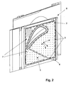
- baffle cooling plate 1 is a perspective view of one already in a platform 4 Gas turbine blade 5 integrated baffle cooling plate 1 shown.
- the baffle cooling plate 1 has 3 impact cooling air openings in addition to the soldering reservoirs already explained above 6, through which cooling air can pass.
- the web-like contact surface 7 can also be seen from FIG which the impact cooling plate 1 is connected to the platform 4.
- the contact surface 7 is on the one hand from the peripheral edge of the baffle cooling plate 1 and on the other hand through the broken lines limited in Fig. 2.
- the solder reservoirs 3 are largely the same distributed to each other and equally spaced from the respective edges of the Contact surface 7 arranged.
- baffle cooling plate 1 provided platform 4, which is otherwise the inner Platform of a rotor blade arranged in a first row of rotor blades in one Gas turbine stage is gas-tight by a cover plate, not shown is closed and thus the baffle cooling plate is an important part of a represents internal cooling system within a gas turbine blade.
Landscapes
- Engineering & Computer Science (AREA)
- Mechanical Engineering (AREA)
- Turbine Rotor Nozzle Sealing (AREA)
Abstract
Description
- Fig. 1
- Flachmaterial mit einer Vielzahl von Lötreservoiren und
- Fig. 2
- perspektivische Darstellung einer Prallluft-gekühlten Plattform einer Gasturbinenschaufel.
- 1
- Fügepartner, Prall-Kühlplatte
- 2
- Durchgangsöffnungen
- 3
- Ausnehmung, Lötreservoir
- 4
- Plattform
- 5
- Gasturbinenschaufel
- 6
- Prall-Kühlluftöffnungen
- 7
- Stegartig ausgebildete Kontaktfläche
Claims (13)
- Vorrichtung zur Herstellung einer Lötverbindung zwischen zwei über eine gemeinsame Kontaktfläche (7) verfügbare Fügepartner, mit einem Lötmaterial das zwischen beiden Fügepartnern einbringbar ist,
dadurch gekennzeichnet, dass wenigstens ein Fügepartner (1) im Bereich der Kontaktfläche (7) wenigstens eine zur Kontaktfläche zugewandte Ausnehmung, ein sogenanntes Lötreservoire (3) vorsieht, in das das Lötmaterial einbringbar ist, und dass das Lötreservoir (3) vollständig von der Kontaktfläche (7) begrenzt und umgeben ist. - Vorrichtung nach Anspruch 1,
dadurch gekennzeichnet, dass wenigstens ein Fügepartner (1), in dem das wenigstens eine Lötreservoir (3) vorgesehen ist, als Flachmaterial ausgebildet ist, und
dass das Lötreservoir (3) eine das Flachmaterial vollständig durchsetzende Öffnung ist. - Vorrichtung nach Anspruch 1 oder 2,
dadurch gekennzeichnet, dass das Lötreservoir (3) eine geradlinig oder gekrümmt verlaufende Langloch-förmige Ausnehmung ist. - Vorrichtung nach einem der Ansprüche 1 bis 3,
dadurch gekennzeichnet, dass das Lötmaterial ein Flüssiglot oder ein verflüssigbares Lötmaterial ist. - Vorrichtung nach einem der Ansprüche 1 bis 4,
dadurch gekennzeichnet, dass das Lötreservoir (3) zur Ausnehmung orientierte abgerundete Begrenzungskanten aufweist. - Vorrichtung nach einem der Ansprüche 1 bis 5,
dadurch gekennzeichnet, dass das wenigstens eine Lötreservoir (3) mittig zur Kontaktfläche (7) angeordnet ist. - Vorrichtung nach einem der Ansprüche 1 bis 6,
dadurch gekennzeichnet, dass eine Vielzahl von Lötreservoirs (3) in dem wenigstens einen Fügepartner (1) vorgesehen sind, die gleich verteilt relativ zur Kontaktfläche (7) angeordnet sind. - Verfahren zur Herstellung einer Lötverbindung zwischen zwei über eine gemeinsame Kontaktfläche (7) verfügbare Fügepartner unter Verwendung der Vorrichtung nach einem der Ansprüche 1 bis 7,
dadurch gekennzeichnet, dass beide Fügepartner über die gemeinsame Kontaktfläche (7) in Kontakt gebracht und gegeneinander fixiert werden,
dass flüssiges Lötmaterial vor in Kontakt bringen oder nachträglich in das wenigstens eine Lötreservoir (3) eingebracht wird,
dass unter Einwirken thermischer Energie das Lötmaterial aus dem Lötreservoir (3) zwischen beide Fügepartner längs der Kontaktfläche (7) eindringt und einen homogenen Lötfilm bildet, und
dass nach Erkalten des Lötfilmes eine homogene flächige Lötverbindung erhalten wird. - Verfahren nach Anspruch 8,
dadurch gekennzeichnet, dass unter Verwendung eines Flachmaterials als Fügepartner, in dem wenigstens ein das Flachmaterial vollständig durchsetzendes Lötreservoir (3) vorgesehen ist, das Lötmaterials in das Lötreservoir (3) eingefüllt wird bis das Lötmaterial nicht mehr weiter zwischen beide Fügepartner eindringt. - Verfahren nach Anspruch 8,
dadurch gekennzeichnet, dass das gegenseitige Fixieren beider Fügepartner mittels Punktschweissen erfolgt. - Verwendung der Vorrichtung zum Verfügen zweier Metallflächenteile.
- Verwendung der Vorrichtung zum Verfügen eines aus einer Super-Legierung bestehenden Flachmaterials mit einem Metallflächenteils.
- Verwendung nach Anspruch 11 oder 12,
dadurch gekennzeichnet, dass eine Prall-Kühlplatte (1) das wenigstens eine Lötreservoir (3) aufweist und mit einer Plattform einer Gasturbinenschaufel (5) verfügt wird.
Applications Claiming Priority (2)
| Application Number | Priority Date | Filing Date | Title |
|---|---|---|---|
| CH11282001 | 2001-06-20 | ||
| CH11282001 | 2001-06-20 |
Publications (2)
| Publication Number | Publication Date |
|---|---|
| EP1270130A1 true EP1270130A1 (de) | 2003-01-02 |
| EP1270130B1 EP1270130B1 (de) | 2010-03-24 |
Family
ID=4559016
Family Applications (1)
| Application Number | Title | Priority Date | Filing Date |
|---|---|---|---|
| EP02405366A Expired - Lifetime EP1270130B1 (de) | 2001-06-20 | 2002-05-06 | Lötverbindung und Verfahren zur Herstellung einer Lötverbindung |
Country Status (3)
| Country | Link |
|---|---|
| US (1) | US6732910B2 (de) |
| EP (1) | EP1270130B1 (de) |
| DE (1) | DE50214298D1 (de) |
Families Citing this family (5)
| Publication number | Priority date | Publication date | Assignee | Title |
|---|---|---|---|---|
| EP1270130B1 (de) * | 2001-06-20 | 2010-03-24 | ALSTOM Technology Ltd | Lötverbindung und Verfahren zur Herstellung einer Lötverbindung |
| DE10327623B4 (de) * | 2003-06-19 | 2006-07-13 | Mtu Aero Engines Gmbh | Fräsverfahren zur Fertigung von Bauteilen |
| US7503113B2 (en) * | 2005-10-13 | 2009-03-17 | Siemens Energy, Inc. | Turbine vane airfoil reconfiguration system |
| US10533425B2 (en) | 2017-12-28 | 2020-01-14 | United Technologies Corporation | Doublet vane assembly for a gas turbine engine |
| JP6508499B1 (ja) * | 2018-10-18 | 2019-05-08 | 三菱日立パワーシステムズ株式会社 | ガスタービン静翼、これを備えているガスタービン、及びガスタービン静翼の製造方法 |
Citations (6)
| Publication number | Priority date | Publication date | Assignee | Title |
|---|---|---|---|---|
| GB330885A (en) | 1928-12-12 | 1930-06-12 | Jakob Schmitt | Improved process and arrangement for manufacturing a soldered or brazed joint |
| FR977750A (fr) * | 1942-10-30 | 1951-04-04 | Radio Electr Soc Fr | Perfectionnements aux procédés de brasage des métaux |
| DE837949C (de) * | 1951-01-30 | 1952-05-05 | Stahl Und Walzwerke Rasselstei | Verfahren zum Verfestigen von Loetnaehten |
| DE2454457B1 (de) * | 1974-11-16 | 1975-06-19 | Voith Getriebe Kg | Hartgelötete verbindung |
| JPS5992161A (ja) * | 1982-11-16 | 1984-05-28 | Sumitomo Electric Ind Ltd | 焼結金属の接合方法 |
| US4787209A (en) * | 1987-04-29 | 1988-11-29 | Avco Corporation | Stacked ring combustor assembly |
Family Cites Families (6)
| Publication number | Priority date | Publication date | Assignee | Title |
|---|---|---|---|---|
| US4125216A (en) * | 1977-01-05 | 1978-11-14 | Stephen Ozimec | Apparatus for accomplishing solder bonding |
| US4747533A (en) * | 1986-04-28 | 1988-05-31 | International Business Machines Corporation | Bonding method and apparatus |
| JPS63140763A (ja) * | 1986-12-03 | 1988-06-13 | Tamura Seisakusho Co Ltd | 自動はんだ付け装置 |
| US5971058A (en) * | 1997-06-13 | 1999-10-26 | International Business Machines Corporation | Apparatus and method for continuous casting solder onto discrete parts |
| US6129257A (en) * | 1999-12-01 | 2000-10-10 | Allison Engine Company, Inc. | High temperature brazing fixture |
| EP1270130B1 (de) * | 2001-06-20 | 2010-03-24 | ALSTOM Technology Ltd | Lötverbindung und Verfahren zur Herstellung einer Lötverbindung |
-
2002
- 2002-05-06 EP EP02405366A patent/EP1270130B1/de not_active Expired - Lifetime
- 2002-05-06 DE DE50214298T patent/DE50214298D1/de not_active Expired - Lifetime
- 2002-06-18 US US10/173,169 patent/US6732910B2/en not_active Expired - Lifetime
Patent Citations (6)
| Publication number | Priority date | Publication date | Assignee | Title |
|---|---|---|---|---|
| GB330885A (en) | 1928-12-12 | 1930-06-12 | Jakob Schmitt | Improved process and arrangement for manufacturing a soldered or brazed joint |
| FR977750A (fr) * | 1942-10-30 | 1951-04-04 | Radio Electr Soc Fr | Perfectionnements aux procédés de brasage des métaux |
| DE837949C (de) * | 1951-01-30 | 1952-05-05 | Stahl Und Walzwerke Rasselstei | Verfahren zum Verfestigen von Loetnaehten |
| DE2454457B1 (de) * | 1974-11-16 | 1975-06-19 | Voith Getriebe Kg | Hartgelötete verbindung |
| JPS5992161A (ja) * | 1982-11-16 | 1984-05-28 | Sumitomo Electric Ind Ltd | 焼結金属の接合方法 |
| US4787209A (en) * | 1987-04-29 | 1988-11-29 | Avco Corporation | Stacked ring combustor assembly |
Non-Patent Citations (1)
| Title |
|---|
| PATENT ABSTRACTS OF JAPAN vol. 008, no. 203 (M - 326) 18 September 1984 (1984-09-18) * |
Also Published As
| Publication number | Publication date |
|---|---|
| US6732910B2 (en) | 2004-05-11 |
| EP1270130B1 (de) | 2010-03-24 |
| DE50214298D1 (de) | 2010-05-06 |
| US20020195479A1 (en) | 2002-12-26 |
Similar Documents
| Publication | Publication Date | Title |
|---|---|---|
| EP1711298B1 (de) | Reparatur-lotverfahren zum reparieren eines bauteils, welches ein basismaterial mit einer gerichteten mikrostruktur umfasst | |
| DE102019215968A1 (de) | Laserschweißverfahren für Eckverbindungen von Werkstückteilen | |
| WO2018145912A1 (de) | Verfahren und vorrichtung für den pulverbettbasierten additiven aufbau einer mehrzahl gleichartiger bauteile | |
| WO2006106061A1 (de) | Verfahren zum reparieren oder erneuern von kühllöchern einer beschichteten komponente einer gasturbine | |
| DE112013004639B4 (de) | Schweißverfahren zum Auftragsschweißen von erosionsbeständigem Metallmaterial und Turbinenschaufel | |
| DE102013213260A1 (de) | Verfahren und Vorrichtung zum Reparieren eines beschädigten Bauteils einer Gasturbine | |
| DE102019001482A1 (de) | Verfahren zum reparieren einer keramischen beschichtung, keramische beschichtung, turbinenelement und gasturbine | |
| WO2019001900A1 (de) | Absaugvorrichtung für die additive fertigung | |
| WO2009065385A1 (de) | Verfahren zur reparatur eines gasturbinenbauteils | |
| EP4317887A1 (de) | Kühlkörper mit einer pulsierenden heatpipe | |
| EP3124162B1 (de) | Verfahren zum herstellen von überlappungsstossschweissverbindungen und überlappungsstossschweissverbindung | |
| EP1270130A1 (de) | Vorrichtung sowie Verfahren zur Herstellung einer Lötverbindung zwischen zwei über eine gemeinsame Kontaktfläche verfügbare Fügepartner | |
| DE19924905C2 (de) | Verfahren zur Erzeugung einer Schweißnaht-Oberfläche beim Laserstrahlschweißen, die für die korrosionssichere Aufbringung eines Oberflächenschutzsystems geeignet ist | |
| DE19630703C2 (de) | Verfahren und Vorrichtung zum Reparaturschweissen von Teilen aus Ni-Basis-Legierungen sowie Anwendung des Verfahrens und Vorrichtung | |
| EP1672690B2 (de) | Mikrokühlkörper | |
| DE102019127813A1 (de) | Kühlvorrichtung, Struktur und Schweißverfahren | |
| EP1293285A1 (de) | Verfahren zur Montage eines Prallblechs | |
| WO2016062396A1 (de) | Verfahren zur herstellung eines plattenwärmetauschers durch zwei schweissungen und entsprechender plattenwärmetauscher | |
| DE102017200123B4 (de) | Befestigungsanordnung | |
| EP1940581B1 (de) | Verfahren zur herstellung einer schweissverbindung | |
| DE102006005364A1 (de) | Verfahren zum Reparieren eines Bauteils | |
| EP2485863A1 (de) | Verfahren zum schmelzschweissen eines einkristallinen werkstücks mit einem polykristallinen werkstück und rotor | |
| DE102018200964A1 (de) | Rotorschaufeldeckband für eine Strömungsmaschine, Rotorschaufel, Verfahren zum Herstellen eines Rotorschaufeldeckbands und einer Rotorschaufel | |
| DE102005015153B4 (de) | Verfahren zum Reparieren oder Erneuern von Kühllöchern einer beschichteten Komponente und beschichtete Komponente mit Kühllöchern einer Gasturbine | |
| DE102015201686A1 (de) | Additives Herstellungsverfahren unter Verwendung dickerer Pulverschichten und Bauteil |
Legal Events
| Date | Code | Title | Description |
|---|---|---|---|
| PUAI | Public reference made under article 153(3) epc to a published international application that has entered the european phase |
Free format text: ORIGINAL CODE: 0009012 |
|
| AK | Designated contracting states |
Kind code of ref document: A1 Designated state(s): AT BE CH CY DE DK ES FI FR GB GR IE IT LI LU MC NL PT SE TR |
|
| AX | Request for extension of the european patent |
Free format text: AL;LT;LV;MK;RO;SI |
|
| 17P | Request for examination filed |
Effective date: 20030604 |
|
| AKX | Designation fees paid |
Designated state(s): DE GB |
|
| RAP1 | Party data changed (applicant data changed or rights of an application transferred) |
Owner name: ALSTOM TECHNOLOGY LTD |
|
| 17Q | First examination report despatched |
Effective date: 20070411 |
|
| RTI1 | Title (correction) |
Free format text: SOLDERED JOINT AND METHOD FOR PRODUCING A SOLDERED JOINT |
|
| GRAP | Despatch of communication of intention to grant a patent |
Free format text: ORIGINAL CODE: EPIDOSNIGR1 |
|
| RIN1 | Information on inventor provided before grant (corrected) |
Inventor name: STENGELE, JOERG, DR. Inventor name: BENEDETTI, BRUNO Inventor name: NAGLER, CHRISTOPH |
|
| GRAS | Grant fee paid |
Free format text: ORIGINAL CODE: EPIDOSNIGR3 |
|
| GRAA | (expected) grant |
Free format text: ORIGINAL CODE: 0009210 |
|
| RIN1 | Information on inventor provided before grant (corrected) |
Inventor name: STENGELE, JOERG, DR. Inventor name: NAGLER, CHRISTOPH Inventor name: BENEDETTI, BRUNO |
|
| AK | Designated contracting states |
Kind code of ref document: B1 Designated state(s): DE GB |
|
| REG | Reference to a national code |
Ref country code: GB Ref legal event code: FG4D Free format text: NOT ENGLISH |
|
| REF | Corresponds to: |
Ref document number: 50214298 Country of ref document: DE Date of ref document: 20100506 Kind code of ref document: P |
|
| PLBE | No opposition filed within time limit |
Free format text: ORIGINAL CODE: 0009261 |
|
| STAA | Information on the status of an ep patent application or granted ep patent |
Free format text: STATUS: NO OPPOSITION FILED WITHIN TIME LIMIT |
|
| 26N | No opposition filed |
Effective date: 20101228 |
|
| PGFP | Annual fee paid to national office [announced via postgrant information from national office to epo] |
Ref country code: DE Payment date: 20160520 Year of fee payment: 15 Ref country code: GB Payment date: 20160520 Year of fee payment: 15 |
|
| REG | Reference to a national code |
Ref country code: DE Ref legal event code: R082 Ref document number: 50214298 Country of ref document: DE Representative=s name: ROESLER, UWE, DIPL.-PHYS.UNIV., DE Ref country code: DE Ref legal event code: R081 Ref document number: 50214298 Country of ref document: DE Owner name: GENERAL ELECTRIC TECHNOLOGY GMBH, CH Free format text: FORMER OWNER: ALSTOM TECHNOLOGY LTD., BADEN, CH |
|
| REG | Reference to a national code |
Ref country code: DE Ref legal event code: R119 Ref document number: 50214298 Country of ref document: DE |
|
| GBPC | Gb: european patent ceased through non-payment of renewal fee |
Effective date: 20170506 |
|
| PG25 | Lapsed in a contracting state [announced via postgrant information from national office to epo] |
Ref country code: DE Free format text: LAPSE BECAUSE OF NON-PAYMENT OF DUE FEES Effective date: 20171201 Ref country code: GB Free format text: LAPSE BECAUSE OF NON-PAYMENT OF DUE FEES Effective date: 20170506 |