EP1270129B1 - Selective removal of brazing compound from joined assemblies - Google Patents
Selective removal of brazing compound from joined assemblies Download PDFInfo
- Publication number
- EP1270129B1 EP1270129B1 EP02253140A EP02253140A EP1270129B1 EP 1270129 B1 EP1270129 B1 EP 1270129B1 EP 02253140 A EP02253140 A EP 02253140A EP 02253140 A EP02253140 A EP 02253140A EP 1270129 B1 EP1270129 B1 EP 1270129B1
- Authority
- EP
- European Patent Office
- Prior art keywords
- nickel
- brazing composition
- components
- composition
- alloy
- Prior art date
- Legal status (The legal status is an assumption and is not a legal conclusion. Google has not performed a legal analysis and makes no representation as to the accuracy of the status listed.)
- Expired - Lifetime
Links
- 238000005219 brazing Methods 0.000 title claims description 37
- 150000001875 compounds Chemical class 0.000 title description 7
- 230000000712 assembly Effects 0.000 title description 3
- 238000000429 assembly Methods 0.000 title description 3
- 239000000203 mixture Substances 0.000 claims description 36
- 238000000034 method Methods 0.000 claims description 32
- XEEYBQQBJWHFJM-UHFFFAOYSA-N Iron Chemical compound [Fe] XEEYBQQBJWHFJM-UHFFFAOYSA-N 0.000 claims description 15
- 229910045601 alloy Inorganic materials 0.000 claims description 15
- 239000000956 alloy Substances 0.000 claims description 15
- PXHVJJICTQNCMI-UHFFFAOYSA-N nickel Substances [Ni] PXHVJJICTQNCMI-UHFFFAOYSA-N 0.000 claims description 12
- 229910000623 nickel–chromium alloy Inorganic materials 0.000 claims description 10
- VEXZGXHMUGYJMC-UHFFFAOYSA-N Hydrochloric acid Chemical compound Cl VEXZGXHMUGYJMC-UHFFFAOYSA-N 0.000 claims description 9
- 229910000990 Ni alloy Inorganic materials 0.000 claims description 9
- 239000003792 electrolyte Substances 0.000 claims description 8
- 229910021607 Silver chloride Inorganic materials 0.000 claims description 6
- 239000011651 chromium Substances 0.000 claims description 6
- 229910052742 iron Inorganic materials 0.000 claims description 6
- 239000010955 niobium Substances 0.000 claims description 6
- HKZLPVFGJNLROG-UHFFFAOYSA-M silver monochloride Chemical compound [Cl-].[Ag+] HKZLPVFGJNLROG-UHFFFAOYSA-M 0.000 claims description 6
- OKTJSMMVPCPJKN-UHFFFAOYSA-N Carbon Chemical compound [C] OKTJSMMVPCPJKN-UHFFFAOYSA-N 0.000 claims description 5
- XUIMIQQOPSSXEZ-UHFFFAOYSA-N Silicon Chemical compound [Si] XUIMIQQOPSSXEZ-UHFFFAOYSA-N 0.000 claims description 5
- RTAQQCXQSZGOHL-UHFFFAOYSA-N Titanium Chemical compound [Ti] RTAQQCXQSZGOHL-UHFFFAOYSA-N 0.000 claims description 5
- 229910052710 silicon Inorganic materials 0.000 claims description 5
- 239000010703 silicon Substances 0.000 claims description 5
- ZOXJGFHDIHLPTG-UHFFFAOYSA-N Boron Chemical compound [B] ZOXJGFHDIHLPTG-UHFFFAOYSA-N 0.000 claims description 3
- 229910052782 aluminium Inorganic materials 0.000 claims description 3
- XAGFODPZIPBFFR-UHFFFAOYSA-N aluminium Chemical compound [Al] XAGFODPZIPBFFR-UHFFFAOYSA-N 0.000 claims description 3
- 229910052796 boron Inorganic materials 0.000 claims description 3
- 229910052799 carbon Inorganic materials 0.000 claims description 3
- 238000002844 melting Methods 0.000 claims description 3
- 230000008018 melting Effects 0.000 claims description 3
- 229910052758 niobium Inorganic materials 0.000 claims description 3
- GUCVJGMIXFAOAE-UHFFFAOYSA-N niobium atom Chemical compound [Nb] GUCVJGMIXFAOAE-UHFFFAOYSA-N 0.000 claims description 3
- 229910052715 tantalum Inorganic materials 0.000 claims description 3
- GUVRBAGPIYLISA-UHFFFAOYSA-N tantalum atom Chemical compound [Ta] GUVRBAGPIYLISA-UHFFFAOYSA-N 0.000 claims description 3
- 239000010936 titanium Substances 0.000 claims description 3
- 229910052719 titanium Inorganic materials 0.000 claims description 3
- RYGMFSIKBFXOCR-UHFFFAOYSA-N Copper Chemical compound [Cu] RYGMFSIKBFXOCR-UHFFFAOYSA-N 0.000 claims description 2
- NINIDFKCEFEMDL-UHFFFAOYSA-N Sulfur Chemical compound [S] NINIDFKCEFEMDL-UHFFFAOYSA-N 0.000 claims description 2
- 229910017052 cobalt Inorganic materials 0.000 claims description 2
- 239000010941 cobalt Substances 0.000 claims description 2
- GUTLYIVDDKVIGB-UHFFFAOYSA-N cobalt atom Chemical compound [Co] GUTLYIVDDKVIGB-UHFFFAOYSA-N 0.000 claims description 2
- 239000010949 copper Substances 0.000 claims description 2
- 229910052802 copper Inorganic materials 0.000 claims description 2
- WPBNNNQJVZRUHP-UHFFFAOYSA-L manganese(2+);methyl n-[[2-(methoxycarbonylcarbamothioylamino)phenyl]carbamothioyl]carbamate;n-[2-(sulfidocarbothioylamino)ethyl]carbamodithioate Chemical compound [Mn+2].[S-]C(=S)NCCNC([S-])=S.COC(=O)NC(=S)NC1=CC=CC=C1NC(=S)NC(=O)OC WPBNNNQJVZRUHP-UHFFFAOYSA-L 0.000 claims description 2
- 239000005864 Sulphur Substances 0.000 claims 1
- 239000004411 aluminium Substances 0.000 claims 1
- 239000000243 solution Substances 0.000 description 17
- 239000000463 material Substances 0.000 description 10
- 239000002253 acid Substances 0.000 description 8
- 238000013019 agitation Methods 0.000 description 5
- 229910052759 nickel Inorganic materials 0.000 description 5
- 150000007513 acids Chemical class 0.000 description 4
- 238000004090 dissolution Methods 0.000 description 4
- 229910052709 silver Inorganic materials 0.000 description 4
- 239000004332 silver Substances 0.000 description 4
- 238000012360 testing method Methods 0.000 description 4
- 238000005530 etching Methods 0.000 description 3
- 229910052500 inorganic mineral Inorganic materials 0.000 description 3
- 238000003760 magnetic stirring Methods 0.000 description 3
- 229910052751 metal Inorganic materials 0.000 description 3
- 239000002184 metal Substances 0.000 description 3
- 239000011707 mineral Substances 0.000 description 3
- XLYOFNOQVPJJNP-UHFFFAOYSA-N water Substances O XLYOFNOQVPJJNP-UHFFFAOYSA-N 0.000 description 3
- GRYLNZFGIOXLOG-UHFFFAOYSA-N Nitric acid Chemical compound O[N+]([O-])=O GRYLNZFGIOXLOG-UHFFFAOYSA-N 0.000 description 2
- NBIIXXVUZAFLBC-UHFFFAOYSA-N Phosphoric acid Chemical compound OP(O)(O)=O NBIIXXVUZAFLBC-UHFFFAOYSA-N 0.000 description 2
- QAOWNCQODCNURD-UHFFFAOYSA-N Sulfuric acid Chemical compound OS(O)(=O)=O QAOWNCQODCNURD-UHFFFAOYSA-N 0.000 description 2
- 239000010953 base metal Substances 0.000 description 2
- 239000008151 electrolyte solution Substances 0.000 description 2
- 239000010439 graphite Substances 0.000 description 2
- 229910002804 graphite Inorganic materials 0.000 description 2
- 230000004048 modification Effects 0.000 description 2
- 238000012986 modification Methods 0.000 description 2
- 229910017604 nitric acid Inorganic materials 0.000 description 2
- 239000000126 substance Substances 0.000 description 2
- 241001630118 Chrysomphalus bifasciculatus Species 0.000 description 1
- 230000009286 beneficial effect Effects 0.000 description 1
- 238000005422 blasting Methods 0.000 description 1
- 238000001311 chemical methods and process Methods 0.000 description 1
- 239000003153 chemical reaction reagent Substances 0.000 description 1
- 239000011248 coating agent Substances 0.000 description 1
- 238000000576 coating method Methods 0.000 description 1
- 239000000306 component Substances 0.000 description 1
- 230000007797 corrosion Effects 0.000 description 1
- 238000005260 corrosion Methods 0.000 description 1
- 230000003247 decreasing effect Effects 0.000 description 1
- 230000001627 detrimental effect Effects 0.000 description 1
- 238000000502 dialysis Methods 0.000 description 1
- 238000009792 diffusion process Methods 0.000 description 1
- 238000004821 distillation Methods 0.000 description 1
- 238000002848 electrochemical method Methods 0.000 description 1
- 230000007613 environmental effect Effects 0.000 description 1
- 229910001026 inconel Inorganic materials 0.000 description 1
- 229910001055 inconels 600 Inorganic materials 0.000 description 1
- NPURPEXKKDAKIH-UHFFFAOYSA-N iodoimino(oxo)methane Chemical compound IN=C=O NPURPEXKKDAKIH-UHFFFAOYSA-N 0.000 description 1
- 238000010030 laminating Methods 0.000 description 1
- 238000005259 measurement Methods 0.000 description 1
- 238000002156 mixing Methods 0.000 description 1
- 230000010287 polarization Effects 0.000 description 1
- 230000000717 retained effect Effects 0.000 description 1
- 229910052717 sulfur Inorganic materials 0.000 description 1
- 239000011593 sulfur Substances 0.000 description 1
Images

Classifications
-
- C—CHEMISTRY; METALLURGY
- C25—ELECTROLYTIC OR ELECTROPHORETIC PROCESSES; APPARATUS THEREFOR
- C25F—PROCESSES FOR THE ELECTROLYTIC REMOVAL OF MATERIALS FROM OBJECTS; APPARATUS THEREFOR
- C25F1/00—Electrolytic cleaning, degreasing, pickling or descaling
- C25F1/02—Pickling; Descaling
- C25F1/04—Pickling; Descaling in solution
-
- C—CHEMISTRY; METALLURGY
- C25—ELECTROLYTIC OR ELECTROPHORETIC PROCESSES; APPARATUS THEREFOR
- C25F—PROCESSES FOR THE ELECTROLYTIC REMOVAL OF MATERIALS FROM OBJECTS; APPARATUS THEREFOR
- C25F5/00—Electrolytic stripping of metallic layers or coatings
-
- B—PERFORMING OPERATIONS; TRANSPORTING
- B23—MACHINE TOOLS; METAL-WORKING NOT OTHERWISE PROVIDED FOR
- B23K—SOLDERING OR UNSOLDERING; WELDING; CLADDING OR PLATING BY SOLDERING OR WELDING; CUTTING BY APPLYING HEAT LOCALLY, e.g. FLAME CUTTING; WORKING BY LASER BEAM
- B23K1/00—Soldering, e.g. brazing, or unsoldering
- B23K1/018—Unsoldering; Removal of melted solder or other residues
-
- B—PERFORMING OPERATIONS; TRANSPORTING
- B23—MACHINE TOOLS; METAL-WORKING NOT OTHERWISE PROVIDED FOR
- B23K—SOLDERING OR UNSOLDERING; WELDING; CLADDING OR PLATING BY SOLDERING OR WELDING; CUTTING BY APPLYING HEAT LOCALLY, e.g. FLAME CUTTING; WORKING BY LASER BEAM
- B23K2101/00—Articles made by soldering, welding or cutting
- B23K2101/001—Turbines
-
- B—PERFORMING OPERATIONS; TRANSPORTING
- B23—MACHINE TOOLS; METAL-WORKING NOT OTHERWISE PROVIDED FOR
- B23K—SOLDERING OR UNSOLDERING; WELDING; CLADDING OR PLATING BY SOLDERING OR WELDING; CUTTING BY APPLYING HEAT LOCALLY, e.g. FLAME CUTTING; WORKING BY LASER BEAM
- B23K35/00—Rods, electrodes, materials, or media, for use in soldering, welding, or cutting
- B23K35/22—Rods, electrodes, materials, or media, for use in soldering, welding, or cutting characterised by the composition or nature of the material
- B23K35/24—Selection of soldering or welding materials proper
- B23K35/30—Selection of soldering or welding materials proper with the principal constituent melting at less than 1550 degrees C
- B23K35/3033—Ni as the principal constituent
- B23K35/304—Ni as the principal constituent with Cr as the next major constituent
Definitions
- the invention relates to a process for selective removal of brazing compound from underlying assemblies and, more particularly, to a process for selective removal of a nickel alloy brazing composition from a nickel-base alloy component according to the preamble of claim 1 (see, for example, US-A-4 324 626)
- Brazing compounds have lower melting points than the materials to be joined.
- the brazing compound will melt and flow into the joint under capillary action.
- brazed assemblies frequently requires the removal of brazing compound so that the joined components can be separated.
- Conventional chemical processes for braze removal from gas turbine engine stators can require 120 hours or longer of exposure to aggressive chemical solutions at high temperature (93°C, 200°F) under continuous ultrasonic agitation. This process requires the use of complex and non-recyclable stripping solutions, and frequently produces detrimental etching of the components.
- EP-A-1010782 discloses a process for electrochemically stripping a coating from an airfoil. recycled so as to reduce environmental impact and cost as well.
- the invention relates to a process for selective removal of nickel alloy brazing compositions from a nickel-base alloy component.
- the process has been developed such that the brazing composition is selectively removed without etching or damaging the underlying components and without the need for aggressive chemicals at high temperatures. Further, the present process does not require the use of non-recyclable stripping solutions.
- a typical environment of use for the process of the present invention is in removing brazing composition from a brazed assembly wherein several nickel-base alloy components are joined together by the brazing composition. It is desirable to remove the brazing composition so as to obtain clean and re-useable underlying components without damaging the underlying components.
- the brazing composition has a lower melting point than the material of the components.
- the brazing composition is selectively removed by immersing the entire assembly including components and brazing composition in a suitable electrolyte or electrolyte-containing solution, and applying a potential across the electrolyte at a magnitude selected so as to dissolve the brazing composition while the underlying components are electrochemically passive whereby the brazing composition is removed without substantial damage to the underlying components.
- brazing composition and component materials include nickel-chromium alloy brazing composition and nickel-chromium alloy components.
- the brazing composition is more preferably a nickel-chromium alloy containing boron, silicon, iron and small amounts of carbon, for example as described in Table 1: TABLE 1 Cr: 7.0 % wt. B: 3.10% wt. Si: 4.50% wt. Fe: 3.0 % wt. C: 0.06% wt. max Ni: remainder.
- the underlying nickel-chromium alloy components are nickel-chromium alloy containing iron, titanium, niobium, tantalum and aluminum, manganese, cobalt, carbon, silicon, copper and small amounts of sulfur.
- the nominal composition, by weight percent, is as set forth in Table 2: TABLE 2 Nominal Composition by Percent C Mn Si S Cr Co Nb+Ta Ni Cu Ti Al Fe - Min - - - - 14.0 - 0.70 70.0 - 2.25 0.40 5.0 % Max 0.80 1.00 0.50 0.01 17.0 1.0 1.20 - 0.50 2.75 1.00 9.0 %
- a particularly desirable electrolyte for use in removing nickel alloy brazing compositions from nickel-base alloy components is a mineral acid solution containing HCl.
- a potential is applied across the electrolyte, for example versus a silver/silver chloride reference electrode, and potential is applied at a magnitude which provides for a relatively high dissolution rate of the brazing composition while the underlying nickel-base alloy components are electrochemically passive.
- the assembly is immersed and potential applied for a suitable period of time until the brazing composition is sufficiently removed from various components and, preferably, the components of the assembly can be removed and separated.
- the used solution can readily be recycled, for example using known techniques such as distillation and diffusion dialysis, so as to provide recycled mineral acid solution for use in further processes in accordance with the present invention.
- the process can advantageously be carried out at ambient temperature, and ultrasonic agitation is not needed.
- the removed solution can advantageously be recycled as described above, and fresh or recycled solution can be fed to the chamber or cell wherein the process is being carried out.
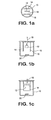
- FIG. 1 schematically illustrates a process in accordance with the present invention.
- a suitable vessel 10 is provided, and an assembly 12 to be treated is positioned therein.
- Assembly 12 is preferably positioned between cathodes 14, 16, which may advantageously be graphite cathodes, and a reference electrode 18 is positioned extending into the solution.
- Assembly 12 may advantageously be suspended in a solution contained within vessel 10, and structures used to suspend assembly 12 should be selected of a material which will not be affected by the conditions and materials within vessel 10.
- a material which will not be affected by the conditions and materials within vessel 10.
- titanium wire is particularly suitable for securing assembly 12 as desired.
- agitation may be accomplished at lab scale using a magnetic stirring bar 20 as shown.
- the process of the present invention provides for effective removal of nickel brazing composition from underlying nickel-based components while avoiding etching or other damage to the components, and this is accomplished using environmentally friendly recyclable materials.
- This example illustrates the beneficial results obtained using a selective removal process in accordance with the present invention.
- the AMS 4777 nickel alloy braze had a composition as follows: Cr 7.0 B 3.10 Si 4.50 Fe 3.0 C 0.06 max Ni REM
- the IN-X750 nickel base alloy had a nominal composition as follows: C Mn Si S Cr Co Nb+Ta Ni Cu Ti Al Fe - Min - - - - 14.0 - 0.70 70.0 - 2.25 0.40 5.0 % Max 0.80 1.00 0.50 0.01 17.0 1.0 1.20 - 0.50 2.75 1.00 9.0 %
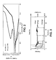
- the IN-X750 base metal is electrochemically passive between the potentials of 0.0 and 0.1 volts versus a silver/silver chloride reference electrode. From the same figure, it can be seen that the AMS 4777 brazing compound dissolves at a relatively high rate (corresponding to a corrosion current density of approximately 10 -2 A/cm 2 ) in this same regime.
- the selective removal of AMS 4777 braze from an IN-X750 component was demonstrated.
- the component was a section of a PW2000 10th stage HPC stator inner shroud.
- a PW2000 10th stage inner shroud section with five vane stubs was suspended in a 2-liter stripping cell as shown in Fig. 1.
- the specimen was approximately four inches (100 mm) in length.
- Honeycomb material was brazed to the inner diameter of the piece.
- Inconel 600 wire was used to suspend the sample in the cell. This wire corroded and failed after 24 hours of testing and was replaced with 99.997% purity titanium wire for the remainder of the test.
- the cell was filled with a 5 volume % solution of technical grade HC1. Gentle magnetic stirring (150 rpm) was used. The sample was polarized to 0.035 V vs. a silver/silver chloride reference electrode. The stripping current was recorded during the run.
- the sample was removed and inspected after 4,8, 16,24, 64 and 89 hours.
- braze fillets were approximately their original size.
- a black smut was produced on the vane stubs.
- the stator base metal was brightened.
- the braze joint was stripped to a depth of approximately 50% of the pocket.
- the vanes were hand-removable from the pockets of the stator.
- the honeycomb detached from the inner shroud with light hand pressure.
- the machined edge of the shroud retained a bright reflective finish.
- FIGS 4a and 4b show, respectively, a stator pocket and vane stub after the process of the present invention. As shown, the stator pocket is free of residual braze, and the vane stub was cleanly removed from the stator pocket.
- This example illustrates current density which is proportional to dissolution rate using different acids.
- Electrochemical measurements on braze material AMS 4777 were made in 4 mineral acids (HCl, HNO 3 ,H 2 SO 4 and H 3 PO 4 ) at three different concentrations of each acid, 5, 10, and 15 volume % of a concentrated technical grade reagent. The measurements were conducted in an EG&G flat cell with 1 cm 2 exposed area of the specimen. The potential was controlled versus Ag/AgCl reference electrode and a high density graphite rod was used as a counter electrode. Polarization scans in all test were from -0.3 V to 1.2 V versus open circuit potential. The Scan rate was 1 V/hr in all tests.
- the current density (which is proportional to the dissolution rate of AMS 4777) in the passive region of the Iconel X-750 was ranging for the different acids as follows: HCl 10 - 100 mA/cm 2 HNO 3 * 2 - 30 mA/cm 2 H 2 SO 4 * 5 - 20 mA/cm 2 H 3 PO 4 * 2 - 6 mA/cm 2 * illustrative examples, not covered by the present invention
- hydrochloric acid in accordance with the present invention provides much higher dissolution rate than the other acids, which makes this acid particularly advantageous for use in the present invention.
Landscapes
- Chemical & Material Sciences (AREA)
- Engineering & Computer Science (AREA)
- Metallurgy (AREA)
- Chemical Kinetics & Catalysis (AREA)
- Electrochemistry (AREA)
- Materials Engineering (AREA)
- Organic Chemistry (AREA)
- Mechanical Engineering (AREA)
- ing And Chemical Polishing (AREA)
- Cleaning And De-Greasing Of Metallic Materials By Chemical Methods (AREA)
- Battery Electrode And Active Subsutance (AREA)
- Laminated Bodies (AREA)
- Braking Arrangements (AREA)
Description
- The invention relates to a process for selective removal of brazing compound from underlying assemblies and, more particularly, to a process for selective removal of a nickel alloy brazing composition from a nickel-base alloy component according to the preamble of claim 1 (see, for example, US-A-4 324 626)
- Metal components are often joined by brazing. Brazing compounds have lower melting points than the materials to be joined. When a metal assembly to be joined is heated with brazing compound near the joint, the brazing compound will melt and flow into the joint under capillary action.
- The repair of brazed assemblies frequently requires the removal of brazing compound so that the joined components can be separated. Conventional chemical processes for braze removal from gas turbine engine stators can require 120 hours or longer of exposure to aggressive chemical solutions at high temperature (93°C, 200°F) under continuous ultrasonic agitation. This process requires the use of complex and non-recyclable stripping solutions, and frequently produces detrimental etching of the components.
- It is clear that the need remains for an improved selective process for removing alloy brazing compositions from nickel-base alloy components without using aggressive stripping solutions and the like so as to provide a more environmentally friendly process.
- In is therefore the primary object of the present invention to provide such a process.
- It is a further object of the invention to provide such a process wherein the materials used can be EP-A-1010782 discloses a process for electrochemically stripping a coating from an airfoil. recycled so as to reduce environmental impact and cost as well.
- In accordance with the present invention, a process is provided as claimed in
claim 1. The invention is characterised over DI by the characterising portion ofclaim 1. - A detailed description of preferred embodiments of the present invention follows, with reference to the attached drawings, wherein:
- Figures 1a, b and c schematically illustrate a process in accordance with the present invention;
- Figure 2 illustrates the relationship between potential versus a silver/silver chloride electrode and current density for a nickel alloy braze composition (AMS 4777) and a nickel base alloy component (INCO X-750) ;
- Figure 3 illustrates the electrochemical record of a braze stripping run in accordance with the present invention; and
- Figures 4a and b show results of a selective process in accordance with the present invention on a stator pocket (Fig. a) and a vane stub (Fig. 4b).
- The invention relates to a process for selective removal of nickel alloy brazing compositions from a nickel-base alloy component. The process has been developed such that the brazing composition is selectively removed without etching or damaging the underlying components and without the need for aggressive chemicals at high temperatures. Further, the present process does not require the use of non-recyclable stripping solutions.
- A typical environment of use for the process of the present invention is in removing brazing composition from a brazed assembly wherein several nickel-base alloy components are joined together by the brazing composition. It is desirable to remove the brazing composition so as to obtain clean and re-useable underlying components without damaging the underlying components.
- The brazing composition has a lower melting point than the material of the components.
- The brazing composition is selectively removed by immersing the entire assembly including components and brazing composition in a suitable electrolyte or electrolyte-containing solution, and applying a potential across the electrolyte at a magnitude selected so as to dissolve the brazing composition while the underlying components are electrochemically passive whereby the brazing composition is removed without substantial damage to the underlying components.
- Particularly suitable combinations of brazing composition and component materials include nickel-chromium alloy brazing composition and nickel-chromium alloy components.
- The brazing composition is more preferably a nickel-chromium alloy containing boron, silicon, iron and small amounts of carbon, for example as described in Table 1:
TABLE 1 Cr: 7.0 % wt. B: 3.10% wt. Si: 4.50% wt. Fe: 3.0 % wt. C: 0.06% wt. max Ni: remainder. - The underlying nickel-chromium alloy components are nickel-chromium alloy containing iron, titanium, niobium, tantalum and aluminum, manganese, cobalt, carbon, silicon, copper and small amounts of sulfur. The nominal composition, by weight percent, is as set forth in Table 2:
TABLE 2 Nominal Composition by Percent C Mn Si S Cr Co Nb+Ta Ni Cu Ti Al Fe - Min - - - - 14.0 - 0.70 70.0 - 2.25 0.40 5.0 % Max 0.80 1.00 0.50 0.01 17.0 1.0 1.20 - 0.50 2.75 1.00 9.0 % - This combination of nickel-chromium alloy braze containing appreciable amounts of boron, silicon and iron and components of nickel-chromium alloy containing iron, titanium, niobium and/or tantalum, and aluminum has been found particularly well suited to use in the method of the present invention for removing the braze from the component.
- It has been found that a particularly desirable electrolyte for use in removing nickel alloy brazing compositions from nickel-base alloy components, in accordance with the present invention, is a mineral acid solution containing HCl.
- A potential is applied across the electrolyte, for example versus a silver/silver chloride reference electrode, and potential is applied at a magnitude which provides for a relatively high dissolution rate of the brazing composition while the underlying nickel-base alloy components are electrochemically passive.
- The assembly is immersed and potential applied for a suitable period of time until the brazing composition is sufficiently removed from various components and, preferably, the components of the assembly can be removed and separated.
- When necessary and/or at the conclusion of the process, the used solution can readily be recycled, for example using known techniques such as distillation and diffusion dialysis, so as to provide recycled mineral acid solution for use in further processes in accordance with the present invention.
- The process can advantageously be carried out at ambient temperature, and ultrasonic agitation is not needed.
- It may be desirable to apply a gentle agitation to the solution using any suitable means, for example so as to mix at a rate equivalent to approximately 150 rpm. At a lab scale, this can be accomplished by positioning a magnetic stirring bar in the electrolyte solution.
- It may also be desirable to remove and replace the solution after certain periods of time. In this case, the removed solution can advantageously be recycled as described above, and fresh or recycled solution can be fed to the chamber or cell wherein the process is being carried out.
- Figure 1 schematically illustrates a process in accordance with the present invention. As shown in Figure 1, a
suitable vessel 10 is provided, and anassembly 12 to be treated is positioned therein.Assembly 12 is preferably positioned betweencathodes reference electrode 18 is positioned extending into the solution. -
Assembly 12 may advantageously be suspended in a solution contained withinvessel 10, and structures used to suspendassembly 12 should be selected of a material which will not be affected by the conditions and materials withinvessel 10. For example, in accordance with the present invention, titanium wire is particularly suitable for securingassembly 12 as desired. - As set forth above, it may be desirable to agitate the electrolyte solution within the
vessel 10, and this may be accomplished, for example using any suitable mixing or agitation device as would be readily known to a person skilled in the art. As set forth above, agitation may be accomplished at lab scale using amagnetic stirring bar 20 as shown. - As will be demonstrated in the following example, the process of the present invention provides for effective removal of nickel brazing composition from underlying nickel-based components while avoiding etching or other damage to the components, and this is accomplished using environmentally friendly recyclable materials.
- This example illustrates the beneficial results obtained using a selective removal process in accordance with the present invention.
- In this example, removal of an AMS 4777 nickel alloy braze from IN-X750 nickel base alloy is demonstrated.
- The AMS 4777 nickel alloy braze had a composition as follows:
Cr 7.0 B 3.10 Si 4.50 Fe 3.0 C 0.06 max Ni REM - The IN-X750 nickel base alloy had a nominal composition as follows:
C Mn Si S Cr Co Nb+Ta Ni Cu Ti Al Fe - Min - - - - 14.0 - 0.70 70.0 - 2.25 0.40 5.0 % Max 0.80 1.00 0.50 0.01 17.0 1.0 1.20 - 0.50 2.75 1.00 9.0 % - Referring to Fig. 2, it can be seen that in a solution of 5 volume % hydrochloric acid in water, the IN-X750 base metal is electrochemically passive between the potentials of 0.0 and 0.1 volts versus a silver/silver chloride reference electrode. From the same figure, it can be seen that the AMS 4777 brazing compound dissolves at a relatively high rate (corresponding to a corrosion current density of approximately 10-2 A/cm2) in this same regime.
- The selective removal of
AMS 4777 braze from an IN-X750 component was demonstrated. The component was a section of a PW2000 10th stage HPC stator inner shroud. - A PW2000 10th stage inner shroud section with five vane stubs was suspended in a 2-liter stripping cell as shown in Fig. 1. The specimen was approximately four inches (100 mm) in length. Honeycomb material was brazed to the inner diameter of the piece.
- Initially, 0.010" (0.254 mm) diameter Inconel 600 wire was used to suspend the sample in the cell. This wire corroded and failed after 24 hours of testing and was replaced with 99.997% purity titanium wire for the remainder of the test.
- The cell was filled with a 5 volume % solution of technical grade HC1. Gentle magnetic stirring (150 rpm) was used. The sample was polarized to 0.035 V vs. a silver/silver chloride reference electrode. The stripping current was recorded during the run.
- The solution was replaced after 16 and 41 hours.
- The sample was removed and inspected after 4,8, 16,24, 64 and 89 hours.
- The current drawn by the sample decreased as the exposed braze area was reduced as shown Fig. 3.
- After 4 hours of the strip cycle, the braze fillets were approximately their original size. A black smut was produced on the vane stubs. The stator base metal was brightened.
- After 8 hours, much of the external braze was removed. The braze joint laminating the two pieces of sheet metal forming the inner shroud was etched.
- After 16 hours, all exterior braze on the OD was removed and the rounded braze fillet was stripped flush with the stator OD. The brown scale on the specimen was removed and engraved serial numbers rendered visible. The machined, smooth surface IN-X750 showed no sign of attack.
- After 41 hours, the braze joint was stripped to a depth of approximately 50% of the pocket.
- After 64 hours, one vane was lightly loose to finger pressure. Rinse water was observed in all of the braze pockets even after repeated compressed air blasting. It was concluded that all of the vane pocket braze joints had perforated to the underlying honeycomb, where water was trapped in the cells and available to wick through the vane pocket. The vanes were file notched to identify them. The process of hand filing the notches produced motion in all five vane sections. The machined, smooth surface IN-X750 still showed no sign of attack.
- After 89 hours, the vanes were hand-removable from the pockets of the stator. The honeycomb detached from the inner shroud with light hand pressure. The machined edge of the shroud retained a bright reflective finish.
- Figures 4a and 4b show, respectively, a stator pocket and vane stub after the process of the present invention. As shown, the stator pocket is free of residual braze, and the vane stub was cleanly removed from the stator pocket.
- This example illustrates current density which is proportional to dissolution rate using different acids.
- Electrochemical measurements on
braze material AMS 4777 were made in 4 mineral acids (HCl, HNO3,H2SO4 and H3PO4) at three different concentrations of each acid, 5, 10, and 15 volume % of a concentrated technical grade reagent. The measurements were conducted in an EG&G flat cell with 1 cm2 exposed area of the specimen. The potential was controlled versus Ag/AgCl reference electrode and a high density graphite rod was used as a counter electrode. Polarization scans in all test were from -0.3 V to 1.2 V versus open circuit potential. The Scan rate was 1 V/hr in all tests. - The current density (which is proportional to the dissolution rate of AMS 4777) in the passive region of the Iconel X-750 was ranging for the different acids as follows:
HCl 10 - 100 mA/cm2 HNO3* 2 - 30 mA/cm2 H2SO4* 5 - 20 mA/cm2 H3PO4* 2 - 6 mA/cm2 * illustrative examples, not covered by the present invention - As can be seen the use of hydrochloric acid in accordance with the present invention provides much higher dissolution rate than the other acids, which makes this acid particularly advantageous for use in the present invention.
- It should be readily apparent that the process in accordance with the present invention provides for advantageous selective removal of brazing composition without damage to the underlying components, and further without using non-recyclable materials under harsh conditions.
- It is to be understood that the invention is not limited to the illustrations described and shown herein, which are deemed to be merely illustrative of the preferred embodiments of the invention, and which are susceptible of modification of form, size, arrangement of parts and details of operation. The invention rather is intended to encompass all such modifications which are within the scope of the following claims.
Claims (5)
- A process for selective removal of a nickel alloy brazing composition from a nickel-base alloy component, comprising the steps of :providing a brazed assembly (12) comprising nickel-base alloy components joined by nickel alloy brazing composition;immersing said assembly in an electrolyte; andapplying a potential across said electrolyte at a magnitude wherein said nickel-base alloy components are electrochemically passive and said nickel alloy brazing composition dissolves whereby said brazing composition is removed from said components,characterised in that:said electrolyte comprises a hydrochloric acid solution;said potential at which the nickel-base alloy components are electrochemically passive is between 0.0 and 0.1 volts versus a Ag/AgCl reference electrode (18) ; andsaid nickel-base alloy components comprise a nickel-chromium alloy containing iron, titanium, niobium, tantalum, aluminium, manganese, cobalt, carbon, silicon, copper and small amounts of sulphur having a nominal composition, by weight percent, as follows:
C Mn Si S Cr Co Nb+Ta Ni Cu Ti Al Fe - Min - - - - 14.0 - 0.70 70.0 - 2.25 0.40 5.0 % Max 0.80 1.00 0.50 0.01 17.0 1.0 1.20 - 0.50 2.75 1.00 9.0 % - The process of claim 1, wherein said brazing composition has a lower melting point than said components.
- The process of claim 1 or 2, wherein said brazing composition comprises nickel-chromium alloy brazing composition.
- The process of any preceding claim, wherein said brazing composition has a composition as follows:Cr: 7.0 % wt.B : 3.10% wt.Si: 4.50% wt.Fe: 3.0 % wt.C : 0.06 % wt. maxNi: remainder.
- The process of claim 1 or 2, wherein said brazing composition is a nickel-chromium alloy containing boron, silicon and iron.
Applications Claiming Priority (2)
| Application Number | Priority Date | Filing Date | Title |
|---|---|---|---|
| US849068 | 2001-05-04 | ||
| US09/849,068 US6719892B2 (en) | 2001-05-04 | 2001-05-04 | Selective removal of brazing compound from joined assemblies |
Publications (3)
| Publication Number | Publication Date |
|---|---|
| EP1270129A2 EP1270129A2 (en) | 2003-01-02 |
| EP1270129A3 EP1270129A3 (en) | 2004-04-21 |
| EP1270129B1 true EP1270129B1 (en) | 2007-01-24 |
Family
ID=25304986
Family Applications (1)
| Application Number | Title | Priority Date | Filing Date |
|---|---|---|---|
| EP02253140A Expired - Lifetime EP1270129B1 (en) | 2001-05-04 | 2002-05-03 | Selective removal of brazing compound from joined assemblies |
Country Status (16)
| Country | Link |
|---|---|
| US (1) | US6719892B2 (en) |
| EP (1) | EP1270129B1 (en) |
| JP (1) | JP2003049287A (en) |
| KR (1) | KR100491159B1 (en) |
| CN (1) | CN1269996C (en) |
| BR (1) | BR0201494A (en) |
| CA (1) | CA2384465C (en) |
| DE (1) | DE60217765T2 (en) |
| HU (1) | HUP0201490A2 (en) |
| IL (1) | IL149327A (en) |
| MX (1) | MXPA02004276A (en) |
| MY (1) | MY134042A (en) |
| PL (1) | PL353723A1 (en) |
| RU (1) | RU2242544C2 (en) |
| SG (1) | SG131739A1 (en) |
| TW (1) | TWI241935B (en) |
Families Citing this family (6)
| Publication number | Priority date | Publication date | Assignee | Title |
|---|---|---|---|---|
| US7303112B2 (en) * | 2004-10-29 | 2007-12-04 | United Technologies Corporation | Repair of braze joint and article repaired |
| US20090274562A1 (en) * | 2008-05-02 | 2009-11-05 | United Technologies Corporation | Coated turbine-stage nozzle segments |
| US9221114B2 (en) * | 2011-12-15 | 2015-12-29 | Advanced Technology Materials, Inc. | Apparatus and method for stripping solder metals during the recycling of waste electrical and electronic equipment |
| US10105795B2 (en) | 2012-05-25 | 2018-10-23 | General Electric Company | Braze compositions, and related devices |
| CN107641780A (en) * | 2017-10-11 | 2018-01-30 | 南通聚星铸锻有限公司 | A kind of Ni-based precipitation hardenable high temperature alloy Technology for Heating Processing |
| CN109940309B (en) * | 2019-05-06 | 2022-03-29 | 衢州学院 | Brazing filler metal composition, and method and welded article for welding nickel-based alloy |
Family Cites Families (12)
| Publication number | Priority date | Publication date | Assignee | Title |
|---|---|---|---|---|
| US3826724A (en) * | 1972-09-11 | 1974-07-30 | O Riggs | Method of removing a metal contaminant |
| US3819494A (en) * | 1973-03-29 | 1974-06-25 | Fountain Plating Co Inc | Method of removing braze |
| US3922396A (en) * | 1974-04-23 | 1975-11-25 | Chromalloy American Corp | Corrosion resistant coating system for ferrous metal articles having brazed joints |
| US4078977A (en) * | 1976-09-13 | 1978-03-14 | Fountain Laurence R | Surface preparation of a damaged braze for rebrazing |
| US4142954A (en) * | 1978-04-14 | 1979-03-06 | Avco Corporation | Electrolytic cleaning of a shrouded blade assembly |
| US4324626A (en) * | 1979-11-13 | 1982-04-13 | United Technologies Corporation | Selective removal of nickel-based braze alloy from nickel-based metals |
| US4261804A (en) | 1979-11-13 | 1981-04-14 | United Technologies Corporation | Selective removal of nickel-based alloys from ferrous-based metals |
| US4399096A (en) * | 1982-06-07 | 1983-08-16 | Williams Gold Refining Company Incorporated | High temperature brazing alloys |
| US5431877A (en) * | 1994-03-02 | 1995-07-11 | Metallgesellschaft Aktiengesellschaft | Process for decreasing the corrosiveness of a sour water |
| US5439637A (en) * | 1994-07-20 | 1995-08-08 | Pyromet Group, Inc. | Debrazing of structures with a powdered wicking agent |
| US5902421A (en) * | 1996-04-09 | 1999-05-11 | General Electric Co. | Nickel-base braze material |
| US6176999B1 (en) * | 1998-12-18 | 2001-01-23 | United Technologies Corporation | Feedback controlled stripping of airfoils |
-
2001
- 2001-05-04 US US09/849,068 patent/US6719892B2/en not_active Expired - Lifetime
-
2002
- 2002-04-23 SG SG200202389-3A patent/SG131739A1/en unknown
- 2002-04-24 IL IL14932702A patent/IL149327A/en not_active IP Right Cessation
- 2002-04-29 MY MYPI20021563A patent/MY134042A/en unknown
- 2002-04-29 MX MXPA02004276A patent/MXPA02004276A/en unknown
- 2002-04-30 TW TW091108971A patent/TWI241935B/en not_active IP Right Cessation
- 2002-04-30 BR BR0201494-7A patent/BR0201494A/en not_active IP Right Cessation
- 2002-05-01 CA CA002384465A patent/CA2384465C/en not_active Expired - Fee Related
- 2002-05-03 EP EP02253140A patent/EP1270129B1/en not_active Expired - Lifetime
- 2002-05-03 KR KR10-2002-0024473A patent/KR100491159B1/en not_active IP Right Cessation
- 2002-05-03 DE DE60217765T patent/DE60217765T2/en not_active Expired - Lifetime
- 2002-05-03 HU HU0201490A patent/HUP0201490A2/en unknown
- 2002-05-03 CN CNB021218749A patent/CN1269996C/en not_active Expired - Fee Related
- 2002-05-06 RU RU2002111651/02A patent/RU2242544C2/en not_active IP Right Cessation
- 2002-05-06 PL PL02353723A patent/PL353723A1/en not_active Application Discontinuation
- 2002-05-07 JP JP2002131956A patent/JP2003049287A/en active Pending
Also Published As
| Publication number | Publication date |
|---|---|
| DE60217765D1 (en) | 2007-03-15 |
| HU0201490D0 (en) | 2002-07-29 |
| KR100491159B1 (en) | 2005-05-24 |
| TWI241935B (en) | 2005-10-21 |
| RU2242544C2 (en) | 2004-12-20 |
| PL353723A1 (en) | 2002-11-18 |
| US20030019761A1 (en) | 2003-01-30 |
| JP2003049287A (en) | 2003-02-21 |
| CN1269996C (en) | 2006-08-16 |
| RU2002111651A (en) | 2004-02-27 |
| MY134042A (en) | 2007-11-30 |
| CA2384465A1 (en) | 2002-11-04 |
| IL149327A (en) | 2005-09-25 |
| CN1385271A (en) | 2002-12-18 |
| SG131739A1 (en) | 2007-05-28 |
| BR0201494A (en) | 2003-02-11 |
| MXPA02004276A (en) | 2004-05-05 |
| IL149327A0 (en) | 2002-11-10 |
| KR20020084832A (en) | 2002-11-11 |
| CA2384465C (en) | 2007-02-20 |
| HUP0201490A2 (en) | 2002-12-28 |
| EP1270129A2 (en) | 2003-01-02 |
| EP1270129A3 (en) | 2004-04-21 |
| DE60217765T2 (en) | 2007-11-15 |
| US6719892B2 (en) | 2004-04-13 |
Similar Documents
| Publication | Publication Date | Title |
|---|---|---|
| US6599416B2 (en) | Method and apparatus for selectively removing coatings from substrates | |
| EP0340300B1 (en) | High temperature metal alloy mixtures for filling holes and repairing damages in superalloy bodies | |
| KR100193389B1 (en) | Austenitic Molybdenum Alloys | |
| JP2004143599A (en) | Method for partially stripping coating from surface of substrate, and related article and composition thereto | |
| EP1270129B1 (en) | Selective removal of brazing compound from joined assemblies | |
| US4894130A (en) | Process for electrolytically detaching a protective coating from a base metal superalloy | |
| CN101672739B (en) | Observation method of silver/titanium/steel brazed joint welding interface metallographic structures | |
| US4944807A (en) | Process for chemically stripping a surface-protection layer with a high chromium content from the main body of a component composed of a nickel-based or cobalt-based superalloy | |
| US4324626A (en) | Selective removal of nickel-based braze alloy from nickel-based metals | |
| US4261804A (en) | Selective removal of nickel-based alloys from ferrous-based metals | |
| US7125457B2 (en) | Method for removing oxide from cracks in turbine components | |
| US6932898B2 (en) | Electrochemical process for the simultaneous stripping of diverse coatings from a metal substrate | |
| JP2599629B2 (en) | Electrolysis method and bath for stripping coating from aluminum substrate | |
| JP4777674B2 (en) | Solder bath erosion reduction tool and soldering apparatus having the same | |
| US20200055615A1 (en) | Method and apparatus for removing coatings | |
| US4026779A (en) | Electrolyte for electrochemically machining nickel base superalloys | |
| US20060137995A1 (en) | Method for removal of metal from a workpiece | |
| EP0340296B1 (en) | Method of repairing damages in superalloys | |
| US20010046585A1 (en) | Method of treating ceramics for use as tips in saws and other tools or other structures | |
| Wang et al. | Corrosion behaviors of 316LN stainless steel joints brazed with Sn-plated silver filler metals | |
| JP2001225226A (en) | Wire electrode for electric discharge cutting of hard metal and method therefor | |
| CA1313596C (en) | High temperature metal alloy mixtures for filling holes and repairing damages in superalloy bodies | |
| JP2630702B2 (en) | Method of peeling and recovering gold or platinum group metal coated on metal substrate and peeling and recovering apparatus | |
| CA1324242C (en) | Method of repairing damages in superalloys | |
| WO2018170843A1 (en) | Electrochemical surface cleaning and plating |
Legal Events
| Date | Code | Title | Description |
|---|---|---|---|
| PUAI | Public reference made under article 153(3) epc to a published international application that has entered the european phase |
Free format text: ORIGINAL CODE: 0009012 |
|
| AK | Designated contracting states |
Kind code of ref document: A2 Designated state(s): AT BE CH CY DE DK ES FI FR GB GR IE IT LI LU MC NL PT SE TR |
|
| AX | Request for extension of the european patent |
Free format text: AL;LT;LV;MK;RO;SI |
|
| PUAL | Search report despatched |
Free format text: ORIGINAL CODE: 0009013 |
|
| AK | Designated contracting states |
Kind code of ref document: A3 Designated state(s): AT BE CH CY DE DK ES FI FR GB GR IE IT LI LU MC NL PT SE TR |
|
| AX | Request for extension of the european patent |
Extension state: AL LT LV MK RO SI |
|
| RIC1 | Information provided on ipc code assigned before grant |
Ipc: 7F 01D 25/00 B Ipc: 7B 23K 1/00 B Ipc: 7C 25F 3/02 B Ipc: 7C 25F 5/00 B Ipc: 7B 23K 1/018 A |
|
| 17P | Request for examination filed |
Effective date: 20040512 |
|
| 17Q | First examination report despatched |
Effective date: 20041006 |
|
| AKX | Designation fees paid |
Designated state(s): CH DE FR GB IT LI SE |
|
| GRAP | Despatch of communication of intention to grant a patent |
Free format text: ORIGINAL CODE: EPIDOSNIGR1 |
|
| GRAS | Grant fee paid |
Free format text: ORIGINAL CODE: EPIDOSNIGR3 |
|
| GRAA | (expected) grant |
Free format text: ORIGINAL CODE: 0009210 |
|
| AK | Designated contracting states |
Kind code of ref document: B1 Designated state(s): CH DE FR GB IT LI SE |
|
| REG | Reference to a national code |
Ref country code: GB Ref legal event code: FG4D |
|
| REG | Reference to a national code |
Ref country code: CH Ref legal event code: EP |
|
| REF | Corresponds to: |
Ref document number: 60217765 Country of ref document: DE Date of ref document: 20070315 Kind code of ref document: P |
|
| REG | Reference to a national code |
Ref country code: CH Ref legal event code: NV Representative=s name: E. BLUM & CO. AG PATENT- UND MARKENANWAELTE VSP |
|
| PGFP | Annual fee paid to national office [announced via postgrant information from national office to epo] |
Ref country code: SE Payment date: 20070503 Year of fee payment: 6 |
|
| REG | Reference to a national code |
Ref country code: SE Ref legal event code: TRGR |
|
| ET | Fr: translation filed | ||
| PLBE | No opposition filed within time limit |
Free format text: ORIGINAL CODE: 0009261 |
|
| STAA | Information on the status of an ep patent application or granted ep patent |
Free format text: STATUS: NO OPPOSITION FILED WITHIN TIME LIMIT |
|
| 26N | No opposition filed |
Effective date: 20071025 |
|
| PG25 | Lapsed in a contracting state [announced via postgrant information from national office to epo] |
Ref country code: IT Free format text: LAPSE BECAUSE OF NON-PAYMENT OF DUE FEES Effective date: 20070503 |
|
| PG25 | Lapsed in a contracting state [announced via postgrant information from national office to epo] |
Ref country code: SE Free format text: LAPSE BECAUSE OF NON-PAYMENT OF DUE FEES Effective date: 20080504 |
|
| REG | Reference to a national code |
Ref country code: FR Ref legal event code: ST Effective date: 20120131 |
|
| PG25 | Lapsed in a contracting state [announced via postgrant information from national office to epo] |
Ref country code: FR Free format text: LAPSE BECAUSE OF NON-PAYMENT OF DUE FEES Effective date: 20110531 |
|
| REG | Reference to a national code |
Ref country code: CH Ref legal event code: PCOW Free format text: NEW ADDRESS: 10 FARM SPRINGS ROAD, FARMINGTON, CT 06032 (US) |
|
| REG | Reference to a national code |
Ref country code: DE Ref legal event code: R082 Ref document number: 60217765 Country of ref document: DE Representative=s name: SCHMITT-NILSON SCHRAUD WAIBEL WOHLFROM PATENTA, DE |
|
| REG | Reference to a national code |
Ref country code: DE Ref legal event code: R082 Ref document number: 60217765 Country of ref document: DE Representative=s name: SCHMITT-NILSON SCHRAUD WAIBEL WOHLFROM PATENTA, DE Ref country code: DE Ref legal event code: R081 Ref document number: 60217765 Country of ref document: DE Owner name: UNITED TECHNOLOGIES CORP. (N.D.GES.D. STAATES , US Free format text: FORMER OWNER: UNITED TECHNOLOGIES CORPORATION, HARTFORD, CONN., US |
|
| PGFP | Annual fee paid to national office [announced via postgrant information from national office to epo] |
Ref country code: FR Payment date: 20170518 Year of fee payment: 16 |
|
| REG | Reference to a national code |
Ref country code: CH Ref legal event code: PL |
|
| PG25 | Lapsed in a contracting state [announced via postgrant information from national office to epo] |
Ref country code: CH Free format text: LAPSE BECAUSE OF NON-PAYMENT OF DUE FEES Effective date: 20180531 Ref country code: LI Free format text: LAPSE BECAUSE OF NON-PAYMENT OF DUE FEES Effective date: 20180531 |
|
| PGFP | Annual fee paid to national office [announced via postgrant information from national office to epo] |
Ref country code: DE Payment date: 20190418 Year of fee payment: 18 |
|
| PGFP | Annual fee paid to national office [announced via postgrant information from national office to epo] |
Ref country code: GB Payment date: 20190423 Year of fee payment: 18 |
|
| REG | Reference to a national code |
Ref country code: DE Ref legal event code: R119 Ref document number: 60217765 Country of ref document: DE |
|
| GBPC | Gb: european patent ceased through non-payment of renewal fee |
Effective date: 20200503 |
|
| PG25 | Lapsed in a contracting state [announced via postgrant information from national office to epo] |
Ref country code: GB Free format text: LAPSE BECAUSE OF NON-PAYMENT OF DUE FEES Effective date: 20200503 |
|
| PG25 | Lapsed in a contracting state [announced via postgrant information from national office to epo] |
Ref country code: DE Free format text: LAPSE BECAUSE OF NON-PAYMENT OF DUE FEES Effective date: 20201201 |