EP1270097A2 - Emptying unit for recovering bottom residue, particularly in drying filters, drying units, and the like - Google Patents
Emptying unit for recovering bottom residue, particularly in drying filters, drying units, and the like Download PDFInfo
- Publication number
- EP1270097A2 EP1270097A2 EP02013493A EP02013493A EP1270097A2 EP 1270097 A2 EP1270097 A2 EP 1270097A2 EP 02013493 A EP02013493 A EP 02013493A EP 02013493 A EP02013493 A EP 02013493A EP 1270097 A2 EP1270097 A2 EP 1270097A2
- Authority
- EP
- European Patent Office
- Prior art keywords
- fluid
- container
- unit according
- emptying unit
- discharge port
- Prior art date
- Legal status (The legal status is an assumption and is not a legal conclusion. Google has not performed a legal analysis and makes no representation as to the accuracy of the status listed.)
- Granted
Links
- 238000001035 drying Methods 0.000 title claims abstract description 24
- 239000012530 fluid Substances 0.000 claims abstract description 35
- 238000002347 injection Methods 0.000 claims description 6
- 239000007924 injection Substances 0.000 claims description 6
- 238000000034 method Methods 0.000 claims description 6
- 239000000126 substance Substances 0.000 claims description 6
- 230000009471 action Effects 0.000 claims description 3
- 230000000694 effects Effects 0.000 claims description 2
- 238000001914 filtration Methods 0.000 description 7
- 239000007788 liquid Substances 0.000 description 2
- 239000000463 material Substances 0.000 description 2
- 230000008569 process Effects 0.000 description 2
- 238000011084 recovery Methods 0.000 description 2
- 238000005406 washing Methods 0.000 description 2
- 230000002860 competitive effect Effects 0.000 description 1
- 239000000356 contaminant Substances 0.000 description 1
- 238000011109 contamination Methods 0.000 description 1
- 230000008878 coupling Effects 0.000 description 1
- 238000010168 coupling process Methods 0.000 description 1
- 238000005859 coupling reaction Methods 0.000 description 1
- 238000007599 discharging Methods 0.000 description 1
- 230000000670 limiting effect Effects 0.000 description 1
- 230000004048 modification Effects 0.000 description 1
- 238000012986 modification Methods 0.000 description 1
- 239000002245 particle Substances 0.000 description 1
- 238000003825 pressing Methods 0.000 description 1
- 238000007790 scraping Methods 0.000 description 1
- 238000000926 separation method Methods 0.000 description 1
- 239000000243 solution Substances 0.000 description 1
Images


Classifications
-
- F—MECHANICAL ENGINEERING; LIGHTING; HEATING; WEAPONS; BLASTING
- F26—DRYING
- F26B—DRYING SOLID MATERIALS OR OBJECTS BY REMOVING LIQUID THEREFROM
- F26B25/00—Details of general application not covered by group F26B21/00 or F26B23/00
- F26B25/001—Handling, e.g. loading or unloading arrangements
- F26B25/002—Handling, e.g. loading or unloading arrangements for bulk goods
-
- B—PERFORMING OPERATIONS; TRANSPORTING
- B01—PHYSICAL OR CHEMICAL PROCESSES OR APPARATUS IN GENERAL
- B01D—SEPARATION
- B01D29/00—Filters with filtering elements stationary during filtration, e.g. pressure or suction filters, not covered by groups B01D24/00 - B01D27/00; Filtering elements therefor
- B01D29/01—Filters with filtering elements stationary during filtration, e.g. pressure or suction filters, not covered by groups B01D24/00 - B01D27/00; Filtering elements therefor with flat filtering elements
-
- B—PERFORMING OPERATIONS; TRANSPORTING
- B01—PHYSICAL OR CHEMICAL PROCESSES OR APPARATUS IN GENERAL
- B01D—SEPARATION
- B01D29/00—Filters with filtering elements stationary during filtration, e.g. pressure or suction filters, not covered by groups B01D24/00 - B01D27/00; Filtering elements therefor
- B01D29/76—Handling the filter cake in the filter for purposes other than for regenerating
- B01D29/80—Handling the filter cake in the filter for purposes other than for regenerating for drying
- B01D29/84—Handling the filter cake in the filter for purposes other than for regenerating for drying by gases or by heating
- B01D29/843—Handling the filter cake in the filter for purposes other than for regenerating for drying by gases or by heating by direct contact with a fluid
-
- B—PERFORMING OPERATIONS; TRANSPORTING
- B01—PHYSICAL OR CHEMICAL PROCESSES OR APPARATUS IN GENERAL
- B01D—SEPARATION
- B01D29/00—Filters with filtering elements stationary during filtration, e.g. pressure or suction filters, not covered by groups B01D24/00 - B01D27/00; Filtering elements therefor
- B01D29/88—Filters with filtering elements stationary during filtration, e.g. pressure or suction filters, not covered by groups B01D24/00 - B01D27/00; Filtering elements therefor having feed or discharge devices
- B01D29/94—Filters with filtering elements stationary during filtration, e.g. pressure or suction filters, not covered by groups B01D24/00 - B01D27/00; Filtering elements therefor having feed or discharge devices for discharging the filter cake, e.g. chutes
-
- B—PERFORMING OPERATIONS; TRANSPORTING
- B08—CLEANING
- B08B—CLEANING IN GENERAL; PREVENTION OF FOULING IN GENERAL
- B08B9/00—Cleaning hollow articles by methods or apparatus specially adapted thereto
- B08B9/08—Cleaning containers, e.g. tanks
- B08B9/093—Cleaning containers, e.g. tanks by the force of jets or sprays
- B08B9/0933—Removing sludge or the like from tank bottoms
-
- F—MECHANICAL ENGINEERING; LIGHTING; HEATING; WEAPONS; BLASTING
- F26—DRYING
- F26B—DRYING SOLID MATERIALS OR OBJECTS BY REMOVING LIQUID THEREFROM
- F26B11/00—Machines or apparatus for drying solid materials or objects with movement which is non-progressive
- F26B11/12—Machines or apparatus for drying solid materials or objects with movement which is non-progressive in stationary drums or other mainly-closed receptacles with moving stirring devices
- F26B11/14—Machines or apparatus for drying solid materials or objects with movement which is non-progressive in stationary drums or other mainly-closed receptacles with moving stirring devices the stirring device moving in a horizontal or slightly-inclined plane
-
- F—MECHANICAL ENGINEERING; LIGHTING; HEATING; WEAPONS; BLASTING
- F26—DRYING
- F26B—DRYING SOLID MATERIALS OR OBJECTS BY REMOVING LIQUID THEREFROM
- F26B21/00—Arrangements or duct systems, e.g. in combination with pallet boxes, for supplying and controlling air or gases for drying solid materials or objects
- F26B21/004—Nozzle assemblies; Air knives; Air distributors; Blow boxes
Landscapes
- Engineering & Computer Science (AREA)
- Mechanical Engineering (AREA)
- Chemical & Material Sciences (AREA)
- Chemical Kinetics & Catalysis (AREA)
- General Engineering & Computer Science (AREA)
- Drying Of Solid Materials (AREA)
- Processing And Handling Of Plastics And Other Materials For Molding In General (AREA)
- Treatment Of Sludge (AREA)
Abstract
Description
- The present invention relates to an emptying unit for recovering bottom residue, particularly in drying filters, drying units, and the like.
- It is known that the drying filters and drying units used in many industrial fields generally comprise a vessel or container that is constituted by a hood-like body which is closed, in a lower region, by a bottom that is monolithic with said body or is hermetically coupled thereto and above which the separator filter may optionally be provided.
- Inside the container there is usually an agitator, which after filtration and drying has ended allows the outward expulsion of the product by means of a hatch that generally opens at the lower lateral or bottom part.
- To prevent the agitator from damaging the filtering element or by scraping the bottom, from introducing possible contaminant particles in the dried product, the agitator must strictly remain spaced from the filter and from the bottom; accordingly, with currently known solutions a bottom residue remains inside the container.
- This bottom residue must be recovered for various reasons; to avoid insufficient separation of batches of two different qualities from a product treatment, the product obtained by a previous process must be fully removed and the apparatus must be cleaned correctly in order to remove the dried product entirely.
- Another reason for which it is necessary to remove the so-called bottom residue is that the residue, which very often has a high economic value, can be spoiled by the subsequent batch being processed, with an evident economical loss.
- Currently, to perform recovery it is necessary to take particular precautions, such as the use of glove boxes or other systems that require protection for the operator, for the environment and for the product and always have very high costs and considerable dimensions.
- The aim of the present invention is to solve the above problems by providing an emptying unit for recovering bottom residue, particularly in drying filters, drying units and the like, that allows to remove completely the dried product and in particular the portion that remains between the lower level reached by the agitator and the filter or bottom of the container, without having to resort to complicated operations with considerable manual interventions.
- Within this aim, a particular object of the invention is to provide an emptying unit that allows total recovery of the bottom residue without compromising in any way the quality of the resulting product and without creating any kind of contamination toward the environment.
- Another object of the present invention is to provide an emptying unit which, by way of its particular constructive characteristics, is capable of giving the greatest assurances of reliability and safety in use.
- Another object of the present invention is to provide an emptying unit for recovering bottom residue, particularly in drying filters, drying units and the like, that can be obtained easily starting from commonly commercially available elements and materials and is further competitive from a merely economical standpoint.
- This aim and these and other objects that will become better apparent hereinafter are achieved by an emptying unit for recovering bottom residue, particularly in drying filters, drying units and the like, according to the invention, characterized in that it comprises, inside a container for treating and containing dried product, means for introducing a fluid for moving the bottom residue of the dried product, a discharge port being further provided which is controlled by a discharge valve interposed on a pneumatic circuit suitable to produce a circulation of fluid in output from said discharge port.
- Further characteristics and advantages of the invention will become better apparent from the following detailed description of some preferred but not exclusive embodiments of an emptying unit and method for recovering bottom residue, particularly in drying filters, drying units and the like, illustrated only by way of non-limitative example in the accompanying drawings, wherein:
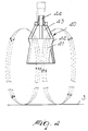
- Figure 1 is a view of the emptying unit in which the movement means are constituted by washing balls and/or rotating elements;
- Figure 2 is a view of a container in which the means for introducing movement fluid are constituted by tori;
- Figure 3 is a view of a container in which the means for introducing movement fluid are constituted by a combination of tori and balls;
- Figure 4 is a view of a particular embodiment of a nozzle.
-
- With reference to the figures, a container is illustrated which is generally designated by the
reference numeral 1 and is constituted, in a per se known manner, by a hood-like body 2 provided with abottom 3 that is coupled hermetically to thebody 2. In the case of drying filters, a conventional filtering element is provided above the bottom. - Inside the container for treating and containing dried
product 1 there is anagitator 4, which is actuated also during the discharge of the dried product to a level at which it does not make contact with the bottom or with the optional filtering element. - It is also possible to provide a
hatch 5 for discharging the dried product until the agitator arrives proximate to the bottom or the filtering element. - The particularity of the invention consists in providing fluid introducing means for introducing a fluid for moving or circulating the bottom residue of the dried product which, as shown in Figure 1, are constituted by a plurality of
balls 10 and/or rotating elements connected to input valves 11 that regulate the inflow of a fluid, generally an inert gaseous substance, which produces an adequate turbulence in the dried product that lies below the region that can be reached by theagitator 4. - In a different embodiment, the
balls 10 can be replaced withtori 20, constituted by one or more annular elements provided withnozzles 21 which are also connected to delivery valves, designated by thereference numeral 22, for the controlled injection of a gaseous substance. - Advantageously, as shown in Figure 3, it is possible to provide a combined system in which both the
balls 10 and thetori 20 are provided. - The fluid introducing means for introducing the movement fluid are connected to vertical translational motion means (50), so that they are lifted during the initial steps of the process inside the drying filter or drying unit, during which the product, dissolved in a liquid, is introduced in order to separate it.
- The fluid introducing means are arranged in the upper part to prevent them, during the treatment step, i.e., the filtration, washing and drying step, from being struck by the product, with the possibility of clogging the various nozzles.
- According to a different embodiment, the fluid introducing means for introducing the movement fluid are constituted by fixed nozzles arranged in the upper part of the treatment chamber formed inside the container.
- As shown in Figure 4, it has been found experimentally that by using a
nozzle 40 having alower portion 41 shaped like a frustum, that widens at the free end and is connected to an upper frustum-shaped portion 42 that widens at an end or side opposite to the free end ofportion 41 towardopenings 43, it is possible to produce a continuous circulation of the gaseous substance. A calibratedair intake port 44 is provided in the upper coupling part above said openings. - This type of nozzle is currently used to agitate liquids contained in tanks and before now it was not used to produce air recirculation.
- In order to allow the outward expulsion of the product, in the
container 1, preferably proximate to the bottom, there is adischarge port 30, which is controlled by adischarge valve 31 interposed on a pneumatic circuit that produces a circulation of a fluid, generally a gaseous fluid, in the direction for flowing out of the container. - For this purpose, downstream of the
discharge valve 31 there is abag filter 32, which is connected to afan 33 and/or compressor driven by amotor 34 which feeds to recirculation a fluid that can be returned into the container by means of arecirculation delivery port 35. - Pneumatic circulation can be achieved both by applying pressure inside the container, so as to loosen and lift the product, and by using vacuum for evacuation; the pressure and the vacuum can be used either individually or selectively in combination; moreover, to facilitate circulation it is possible to provide an
injection inlet 36 for a conveyance fluid downstream of the discharge valve in order to generate a Venturi effect. - The pressure for evacuation can be generated from above, from below, tangentially with respect to the bottom or tangentially with respect to the filtering element, and likewise the pressure can be applied also optionally from below in combination with an action from above.
- With the arrangement described above it is thus possible to provide a method suitable to empty the dried product completely, utilizing a movement of the product that constitutes the product residue that is obtained by introducing a gaseous substance by way of suitable nozzles that produce, in practice, a stream for conveying the product outward.
- It should be added to the above that it is possible to utilize pneumatic conveyance also to empty the container without performing preliminary emptying by means of the hatch, but by performing complete emptying with an initial step of pneumatic conveyance and a final step with pneumatic conveyance that also allows to remove the product left on the bottom.
- The invention thus conceived is susceptible of numerous modifications and variations, all of which are within the scope of the appended claims.
- All the details may further be replaced with other technically equivalent elements.
- In practice, the materials used, as well as the contingent shapes and dimensions, may be any according to requirements.
- The disclosures in Italian Patent Application No. MI2001A001351 from which this application claims priority are incorporated herein by reference.
- Where technical features mentioned in any claim are followed by reference signs, those reference signs have been included for the sole purpose of increasing the intelligibility of the claims and accordingly, such reference signs do not have any limiting effect on the interpretation of each element identified by way of example by such reference signs.
Claims (14)
- An emptying unit for recovering bottom residue, particularly in drying filters, drying units and the like, characterized in that it comprises, inside a container (1) for treating and containing dried product, fluid introducing means (10, 20, 40) for introducing a fluid for moving the bottom residue of the dried product, a discharge port (30) being further provided which is controlled by a discharge valve (31) interposed on a pneumatic circuit suitable to produce a circulation of fluid in output from said discharge port (30).
- The emptying unit according to claim 1, characterized in that said discharge port (30) is arranged proximate to the bottom (3) of said container (1).
- The emptying unit according to the preceding claims, characterized in that said fluid introducing means for moving the bottom residue comprise a plurality of balls and/or rotating elements (10) operatively connected to injection valves (11) that control the inflow of a fluid.
- The emptying unit according to one or more of the preceding claims, characterized in that said fluid introducing means for moving the bottom residue comprise at least one annular element (21), which is provided with a plurality of nozzles for introducing a fluid, said at least one annular element being operatively connected to a delivery valve (22) for controlling the injection of a fluid.
- The emptying unit according to one or more of the preceding claims, characterized in that said fluid is constituted by an inert gaseous substance.
- The emptying unit according to one or more of the preceding claims, characterized in that said fluid introducing means for moving the bottom residue are connected to vertical translational motion means (50) for lifting said fluid introducing means during the initial steps of processing inside said container (1).
- The emptying unit according to one or more of the preceding claims, characterized in that said fluid introducing means comprise nozzles (40) which are arranged in a fixed position in said container (1).
- The emptying unit according to one or more of the preceding claims, characterized in that said nozzles (40) comprise a lower frustum-shaped portion (41) that widens toward the free end and is connected to an upper frustum-shaped portion (42) that widens on the opposite side toward openings (43) arranged below a calibrated air intake port (44).
- The emptying unit according to one or more of the preceding claims, characterized in that it comprises, downstream of said discharge valve (31), a bag filter (32) that is connected to a fan and/or compressor (33) driven by a motor (34) and to an injection port (35) of the extracted fluid for recirculation.
- The emptying unit according to one or more of the preceding claims, characterized in that pneumatic circulation is performed by generating pressure inside said container (1).
- The emptying unit according to one or more of the preceding claims, characterized in that pneumatic circulation is achieved by producing a vacuum at said discharge valve (31).
- The emptying unit according to one or more of the preceding claims, characterized in that said pneumatic circulation is obtained from the combination of the action of pressure inside said container (1) and the action of vacuum downstream of said container (1).
- The emptying unit according to one or more of the preceding claims, characterized in that it comprises, at said discharge valve (31), an injection inlet (36) for a gaseous substance adapted to produce a Venturi effect.
- Method for recovering a bottom residue by emptying a container of a drying unit having a discharge port, a pneumatic circuit connected to the discharge port and a discharge valve for controlling flow through said discharge port and in said pneumatic circuit, the method comprising the steps of: providing at the container, fluid introducing means; and introducing through said fluid introducing means into said container, a fluid flow for moving bottom residues of a dried product and to produce a circulation of fluid in output from the discharge port.
Applications Claiming Priority (2)
| Application Number | Priority Date | Filing Date | Title |
|---|---|---|---|
| IT2001MI001351A ITMI20011351A1 (en) | 2001-06-27 | 2001-06-27 | EMPTYING GROUP FOR THE RECOVERY OF THE REMAINING RESIDUE PARTICULARLY IN DRYING FILTERS DRYING AND SIMILAR |
| ITMI20011351 | 2001-06-27 |
Publications (3)
| Publication Number | Publication Date |
|---|---|
| EP1270097A2 true EP1270097A2 (en) | 2003-01-02 |
| EP1270097A3 EP1270097A3 (en) | 2004-02-04 |
| EP1270097B1 EP1270097B1 (en) | 2008-07-23 |
Family
ID=11447942
Family Applications (1)
| Application Number | Title | Priority Date | Filing Date |
|---|---|---|---|
| EP02013493A Expired - Lifetime EP1270097B1 (en) | 2001-06-27 | 2002-06-17 | Emptying unit for recovering bottom residue, particularly in drying filters, drying units, and the like |
Country Status (6)
| Country | Link |
|---|---|
| US (1) | US6959504B2 (en) |
| EP (1) | EP1270097B1 (en) |
| AT (1) | ATE401974T1 (en) |
| DE (1) | DE60227746D1 (en) |
| ES (1) | ES2311569T3 (en) |
| IT (1) | ITMI20011351A1 (en) |
Cited By (6)
| Publication number | Priority date | Publication date | Assignee | Title |
|---|---|---|---|---|
| FR2865144A1 (en) * | 2004-01-21 | 2005-07-22 | Tournaire Sa | Liquid/solid separator for use in chemistry, pharmacy and agro-food industry has suction unit to remove accumulated powder from filter surface |
| WO2005113107A1 (en) * | 2004-05-23 | 2005-12-01 | Rosenmund Vta Ag | Method and device for removal of residual products |
| WO2007096909A1 (en) * | 2006-02-22 | 2007-08-30 | Comber S.R.L. | Filter/dryer |
| CN109570104A (en) * | 2018-10-30 | 2019-04-05 | 长春理工大学光电信息学院 | The intelligent cleaning device of a kind of electronic equipment production |
| CN110986559A (en) * | 2019-12-24 | 2020-04-10 | 李敏 | Even drying device of agricultural seed |
| CN111412738A (en) * | 2020-04-15 | 2020-07-14 | 武汉谷劲科技有限公司 | Agricultural feed drying device |
Families Citing this family (14)
| Publication number | Priority date | Publication date | Assignee | Title |
|---|---|---|---|---|
| US20040050802A1 (en) * | 2002-05-17 | 2004-03-18 | Banister John Patrick | Fluid bed filter-dryer apparatus |
| US7211249B2 (en) * | 2003-03-17 | 2007-05-01 | Color Access, Inc. | Heat-generating composition for topical application to skin |
| FI20115350A0 (en) | 2011-04-12 | 2011-04-12 | Steris Europe Inc | A device for separating a solid from a biowaste suspension |
| AU2013202643B2 (en) * | 2012-02-23 | 2015-10-29 | Prime Services Trustee Limited | Process for recovering valuable or harmful water-miscible liquids from slurries and an apparatus therefor |
| ITUB20152211A1 (en) * | 2015-07-15 | 2017-01-15 | Delta Costruzioni Mecc S R L | DEVICE AND METHOD TO SEPARATE THE SOLID FRACTION FROM THE LIQUID FRACTION OF A TURBID |
| CN104930847A (en) * | 2015-07-15 | 2015-09-23 | 南京高捷轻工设备有限公司 | Wet solid material feeding device with pre-drying function and pre-drying feeding method thereof |
| EP3806975A1 (en) * | 2018-06-13 | 2021-04-21 | Cargill, Incorporated | Liquid discharge filter and its use |
| CN109332323A (en) * | 2018-11-20 | 2019-02-15 | 佛山科学技术学院 | A kind of plating water treatment tank cleaning device |
| CN109489348A (en) * | 2018-12-26 | 2019-03-19 | 天津莱沃真空干燥设备制造有限公司 | The nitrogen protection microwave vacuum drying device and drying means of optical plastic raw material |
| US11911719B2 (en) * | 2019-09-20 | 2024-02-27 | Massachusetts Institute Of Technology | Devices and methods for the integrated filtration, drying, and mechanical processing of active pharmaceutical ingredients |
| US11471798B2 (en) * | 2020-11-10 | 2022-10-18 | Regfilter, S.L. | Liquid filtration system |
| CN113465330A (en) * | 2021-05-19 | 2021-10-01 | 滁州欣发食品有限公司 | Energy-saving drying equipment is used in food additive production |
| CN114459225A (en) * | 2022-03-30 | 2022-05-10 | 唐山市丰南区金翔化纤有限公司 | Energy-saving preheating system for polyester chips for chemical fibers |
| CN116951927B (en) * | 2023-08-01 | 2024-04-05 | 山东彩客新材料有限公司 | Filter cake drying device for iron phosphate preparation and drying method thereof |
Family Cites Families (9)
| Publication number | Priority date | Publication date | Assignee | Title |
|---|---|---|---|---|
| GB1562592A (en) | 1976-08-12 | 1980-03-12 | Cp Equipment Ltd | Tank cleaning apparatus |
| US4157281A (en) * | 1977-07-14 | 1979-06-05 | Systems Technology Corp | Method and apparatus for reclaiming solvents from solvent-bearing sludge material |
| US4912181A (en) * | 1987-10-20 | 1990-03-27 | Raychem Corporation | Preparation of poly(arylene ether ketones) by sequential oligomerization and polyerization in distinct reaction zones |
| US5564350A (en) * | 1994-01-27 | 1996-10-15 | Peplinski; Mark E. | Method and apparatus for removal of residual product |
| US5546676A (en) * | 1995-05-17 | 1996-08-20 | Mallinckrodt Medical, Inc. | Aggressive convective drying in an agitated pan type dryer |
| US6159435A (en) * | 1996-05-06 | 2000-12-12 | Atomaer Pty Ltd | Leaching of mineral ores |
| US5813801A (en) | 1996-06-28 | 1998-09-29 | Mac Equipment, Inc. | Dense phase particulate conveying system and method with continuous air leakage management |
| JP3168175B2 (en) * | 1997-05-13 | 2001-05-21 | 三岐通運株式会社 | Cleaning plant for powder tank room of powder transport tank car |
| US6216612B1 (en) * | 1999-09-01 | 2001-04-17 | American Electric Power Service Corporation | Ultra fine fly ash and a system for collecting the same |
-
2001
- 2001-06-27 IT IT2001MI001351A patent/ITMI20011351A1/en unknown
-
2002
- 2002-06-17 US US10/171,666 patent/US6959504B2/en not_active Expired - Fee Related
- 2002-06-17 AT AT02013493T patent/ATE401974T1/en not_active IP Right Cessation
- 2002-06-17 ES ES02013493T patent/ES2311569T3/en not_active Expired - Lifetime
- 2002-06-17 DE DE60227746T patent/DE60227746D1/en not_active Expired - Lifetime
- 2002-06-17 EP EP02013493A patent/EP1270097B1/en not_active Expired - Lifetime
Cited By (7)
| Publication number | Priority date | Publication date | Assignee | Title |
|---|---|---|---|---|
| FR2865144A1 (en) * | 2004-01-21 | 2005-07-22 | Tournaire Sa | Liquid/solid separator for use in chemistry, pharmacy and agro-food industry has suction unit to remove accumulated powder from filter surface |
| WO2005113107A1 (en) * | 2004-05-23 | 2005-12-01 | Rosenmund Vta Ag | Method and device for removal of residual products |
| US7473375B2 (en) | 2004-05-23 | 2009-01-06 | Rosenmund Vta Ag | Method and device for removal of residual products |
| WO2007096909A1 (en) * | 2006-02-22 | 2007-08-30 | Comber S.R.L. | Filter/dryer |
| CN109570104A (en) * | 2018-10-30 | 2019-04-05 | 长春理工大学光电信息学院 | The intelligent cleaning device of a kind of electronic equipment production |
| CN110986559A (en) * | 2019-12-24 | 2020-04-10 | 李敏 | Even drying device of agricultural seed |
| CN111412738A (en) * | 2020-04-15 | 2020-07-14 | 武汉谷劲科技有限公司 | Agricultural feed drying device |
Also Published As
| Publication number | Publication date |
|---|---|
| US6959504B2 (en) | 2005-11-01 |
| EP1270097A3 (en) | 2004-02-04 |
| ES2311569T3 (en) | 2009-02-16 |
| ATE401974T1 (en) | 2008-08-15 |
| ITMI20011351A0 (en) | 2001-06-27 |
| ITMI20011351A1 (en) | 2002-12-27 |
| EP1270097B1 (en) | 2008-07-23 |
| DE60227746D1 (en) | 2008-09-04 |
| US20030000101A1 (en) | 2003-01-02 |
Similar Documents
| Publication | Publication Date | Title |
|---|---|---|
| US6959504B2 (en) | Emptying unit for recovering bottom residue, particularly in drying filters, drying units, and the like | |
| EP1277506B1 (en) | System for discharging dried product, particularly for drying filters, drying units and the like | |
| US4784169A (en) | Apparatus for treating articles with solution to remove solids and then filtering the solution | |
| JP5155315B2 (en) | Cleaning device and method for cleaning a workpiece | |
| US5470473A (en) | Rotary vacuum filtration drum with valved hopper cake treatment means | |
| EP1166847A2 (en) | Apparatus for treating industrial waste products | |
| JP3599703B2 (en) | Powder dryer | |
| JP4261658B2 (en) | Stir processing device | |
| JPH08215509A (en) | Filter medium washer in moving filter bed type filter | |
| EP3216507B1 (en) | Method and device for improved prefiltration | |
| JP2002370002A (en) | Multistage countercurrent crystallizer | |
| CN115646939B (en) | Water pump casting cleaning device and implementation method thereof | |
| EP3436226B1 (en) | Method for washing and separating pieces of plastics material, and washing and separating group for pieces of plastics | |
| GB2152398A (en) | Apparatus for chemically removing solid matter from articles | |
| JPH05277303A (en) | Solid extractor | |
| EP1361022A2 (en) | Circular vibratory finishing machine with automatic separation of the parts to be treated and of the finishing media | |
| WO2000071226A1 (en) | Pressure filtration device and method employing a depressurizing chamber and material transport | |
| JP3683568B2 (en) | Centrifuge method and centrifuge | |
| CN105903250B (en) | There is filter cloth vacuum suction filter filter cloth pull of vacuum washing system | |
| WO2006032845A1 (en) | Soil cleaning method and apparatus | |
| KR101582112B1 (en) | Chip-size Silicon Cleaning Method and Apparatus | |
| US1061660A (en) | Separation of liquids from crushed-ore products. | |
| JP7117073B2 (en) | powder agitator | |
| CN108483708A (en) | A kind of metallurgy sewage treatment equipment | |
| US954466A (en) | Apparatus for recovering values from ore solutions. |
Legal Events
| Date | Code | Title | Description |
|---|---|---|---|
| PUAI | Public reference made under article 153(3) epc to a published international application that has entered the european phase |
Free format text: ORIGINAL CODE: 0009012 |
|
| AK | Designated contracting states |
Kind code of ref document: A2 Designated state(s): AT BE CH CY DE DK ES FI FR GB GR IE IT LI LU MC NL PT SE TR |
|
| AX | Request for extension of the european patent |
Free format text: AL;LT;LV;MK;RO;SI |
|
| PUAL | Search report despatched |
Free format text: ORIGINAL CODE: 0009013 |
|
| AK | Designated contracting states |
Kind code of ref document: A3 Designated state(s): AT BE CH CY DE DK ES FI FR GB GR IE IT LI LU MC NL PT SE TR |
|
| AX | Request for extension of the european patent |
Extension state: AL LT LV MK RO SI |
|
| RIC1 | Information provided on ipc code assigned before grant |
Ipc: 7B 01D 35/16 B Ipc: 7B 08B 5/02 B Ipc: 7B 08B 9/093 A Ipc: 7B 01D 29/01 B |
|
| 17P | Request for examination filed |
Effective date: 20040706 |
|
| AKX | Designation fees paid |
Designated state(s): AT BE CH CY DE DK ES FI FR GB GR IE IT LI LU MC NL PT SE TR |
|
| 17Q | First examination report despatched |
Effective date: 20050322 |
|
| 17Q | First examination report despatched |
Effective date: 20050322 |
|
| RIC1 | Information provided on ipc code assigned before grant |
Ipc: B01D 29/01 20060101ALI20071219BHEP Ipc: B08B 9/093 20060101AFI20071219BHEP Ipc: F26B 21/00 20060101ALN20071219BHEP Ipc: F26B 25/00 20060101ALN20071219BHEP Ipc: B01D 35/16 20060101ALI20071219BHEP Ipc: B08B 5/02 20060101ALI20071219BHEP Ipc: F26B 11/14 20060101ALN20071219BHEP |
|
| GRAP | Despatch of communication of intention to grant a patent |
Free format text: ORIGINAL CODE: EPIDOSNIGR1 |
|
| GRAS | Grant fee paid |
Free format text: ORIGINAL CODE: EPIDOSNIGR3 |
|
| GRAA | (expected) grant |
Free format text: ORIGINAL CODE: 0009210 |
|
| AK | Designated contracting states |
Kind code of ref document: B1 Designated state(s): AT BE CH CY DE DK ES FI FR GB GR IE IT LI LU MC NL PT SE TR |
|
| REG | Reference to a national code |
Ref country code: GB Ref legal event code: FG4D |
|
| REG | Reference to a national code |
Ref country code: CH Ref legal event code: EP |
|
| REG | Reference to a national code |
Ref country code: IE Ref legal event code: FG4D |
|
| REF | Corresponds to: |
Ref document number: 60227746 Country of ref document: DE Date of ref document: 20080904 Kind code of ref document: P |
|
| REG | Reference to a national code |
Ref country code: CH Ref legal event code: NV Representative=s name: PATENTANWAELTE SCHAAD, BALASS, MENZL & PARTNER AG |
|
| NLV1 | Nl: lapsed or annulled due to failure to fulfill the requirements of art. 29p and 29m of the patents act | ||
| PG25 | Lapsed in a contracting state [announced via postgrant information from national office to epo] |
Ref country code: PT Free format text: LAPSE BECAUSE OF FAILURE TO SUBMIT A TRANSLATION OF THE DESCRIPTION OR TO PAY THE FEE WITHIN THE PRESCRIBED TIME-LIMIT Effective date: 20081223 Ref country code: NL Free format text: LAPSE BECAUSE OF FAILURE TO SUBMIT A TRANSLATION OF THE DESCRIPTION OR TO PAY THE FEE WITHIN THE PRESCRIBED TIME-LIMIT Effective date: 20080723 |
|
| REG | Reference to a national code |
Ref country code: ES Ref legal event code: FG2A Ref document number: 2311569 Country of ref document: ES Kind code of ref document: T3 |
|
| PG25 | Lapsed in a contracting state [announced via postgrant information from national office to epo] |
Ref country code: FI Free format text: LAPSE BECAUSE OF FAILURE TO SUBMIT A TRANSLATION OF THE DESCRIPTION OR TO PAY THE FEE WITHIN THE PRESCRIBED TIME-LIMIT Effective date: 20080723 Ref country code: AT Free format text: LAPSE BECAUSE OF FAILURE TO SUBMIT A TRANSLATION OF THE DESCRIPTION OR TO PAY THE FEE WITHIN THE PRESCRIBED TIME-LIMIT Effective date: 20080723 |
|
| PG25 | Lapsed in a contracting state [announced via postgrant information from national office to epo] |
Ref country code: BE Free format text: LAPSE BECAUSE OF FAILURE TO SUBMIT A TRANSLATION OF THE DESCRIPTION OR TO PAY THE FEE WITHIN THE PRESCRIBED TIME-LIMIT Effective date: 20080723 |
|
| PG25 | Lapsed in a contracting state [announced via postgrant information from national office to epo] |
Ref country code: DK Free format text: LAPSE BECAUSE OF FAILURE TO SUBMIT A TRANSLATION OF THE DESCRIPTION OR TO PAY THE FEE WITHIN THE PRESCRIBED TIME-LIMIT Effective date: 20080723 |
|
| PLBE | No opposition filed within time limit |
Free format text: ORIGINAL CODE: 0009261 |
|
| STAA | Information on the status of an ep patent application or granted ep patent |
Free format text: STATUS: NO OPPOSITION FILED WITHIN TIME LIMIT |
|
| 26N | No opposition filed |
Effective date: 20090424 |
|
| PG25 | Lapsed in a contracting state [announced via postgrant information from national office to epo] |
Ref country code: SE Free format text: LAPSE BECAUSE OF FAILURE TO SUBMIT A TRANSLATION OF THE DESCRIPTION OR TO PAY THE FEE WITHIN THE PRESCRIBED TIME-LIMIT Effective date: 20081023 Ref country code: MC Free format text: LAPSE BECAUSE OF NON-PAYMENT OF DUE FEES Effective date: 20090630 |
|
| PG25 | Lapsed in a contracting state [announced via postgrant information from national office to epo] |
Ref country code: GR Free format text: LAPSE BECAUSE OF FAILURE TO SUBMIT A TRANSLATION OF THE DESCRIPTION OR TO PAY THE FEE WITHIN THE PRESCRIBED TIME-LIMIT Effective date: 20081024 |
|
| PG25 | Lapsed in a contracting state [announced via postgrant information from national office to epo] |
Ref country code: LU Free format text: LAPSE BECAUSE OF NON-PAYMENT OF DUE FEES Effective date: 20090617 |
|
| PGFP | Annual fee paid to national office [announced via postgrant information from national office to epo] |
Ref country code: CH Payment date: 20110608 Year of fee payment: 10 |
|
| PG25 | Lapsed in a contracting state [announced via postgrant information from national office to epo] |
Ref country code: TR Free format text: LAPSE BECAUSE OF FAILURE TO SUBMIT A TRANSLATION OF THE DESCRIPTION OR TO PAY THE FEE WITHIN THE PRESCRIBED TIME-LIMIT Effective date: 20080723 |
|
| PG25 | Lapsed in a contracting state [announced via postgrant information from national office to epo] |
Ref country code: CY Free format text: LAPSE BECAUSE OF FAILURE TO SUBMIT A TRANSLATION OF THE DESCRIPTION OR TO PAY THE FEE WITHIN THE PRESCRIBED TIME-LIMIT Effective date: 20080723 |
|
| PGFP | Annual fee paid to national office [announced via postgrant information from national office to epo] |
Ref country code: GB Payment date: 20120924 Year of fee payment: 11 Ref country code: IE Payment date: 20120911 Year of fee payment: 11 |
|
| PGFP | Annual fee paid to national office [announced via postgrant information from national office to epo] |
Ref country code: DE Payment date: 20120829 Year of fee payment: 11 Ref country code: FR Payment date: 20120925 Year of fee payment: 11 Ref country code: IT Payment date: 20120829 Year of fee payment: 11 |
|
| PGFP | Annual fee paid to national office [announced via postgrant information from national office to epo] |
Ref country code: ES Payment date: 20120926 Year of fee payment: 11 |
|
| REG | Reference to a national code |
Ref country code: CH Ref legal event code: PL |
|
| GBPC | Gb: european patent ceased through non-payment of renewal fee |
Effective date: 20130617 |
|
| REG | Reference to a national code |
Ref country code: IE Ref legal event code: MM4A |
|
| REG | Reference to a national code |
Ref country code: DE Ref legal event code: R119 Ref document number: 60227746 Country of ref document: DE Effective date: 20140101 |
|
| REG | Reference to a national code |
Ref country code: FR Ref legal event code: ST Effective date: 20140228 |
|
| PG25 | Lapsed in a contracting state [announced via postgrant information from national office to epo] |
Ref country code: IE Free format text: LAPSE BECAUSE OF NON-PAYMENT OF DUE FEES Effective date: 20130617 Ref country code: LI Free format text: LAPSE BECAUSE OF NON-PAYMENT OF DUE FEES Effective date: 20130630 Ref country code: DE Free format text: LAPSE BECAUSE OF NON-PAYMENT OF DUE FEES Effective date: 20140101 Ref country code: GB Free format text: LAPSE BECAUSE OF NON-PAYMENT OF DUE FEES Effective date: 20130617 Ref country code: CH Free format text: LAPSE BECAUSE OF NON-PAYMENT OF DUE FEES Effective date: 20130630 |
|
| PG25 | Lapsed in a contracting state [announced via postgrant information from national office to epo] |
Ref country code: FR Free format text: LAPSE BECAUSE OF NON-PAYMENT OF DUE FEES Effective date: 20130701 Ref country code: IT Free format text: LAPSE BECAUSE OF NON-PAYMENT OF DUE FEES Effective date: 20130617 |
|
| REG | Reference to a national code |
Ref country code: ES Ref legal event code: FD2A Effective date: 20140707 |
|
| PG25 | Lapsed in a contracting state [announced via postgrant information from national office to epo] |
Ref country code: ES Free format text: LAPSE BECAUSE OF NON-PAYMENT OF DUE FEES Effective date: 20130618 |