EP1269904A1 - Upright vacuum cleaner having detachable upright handle - Google Patents
Upright vacuum cleaner having detachable upright handle Download PDFInfo
- Publication number
- EP1269904A1 EP1269904A1 EP02445080A EP02445080A EP1269904A1 EP 1269904 A1 EP1269904 A1 EP 1269904A1 EP 02445080 A EP02445080 A EP 02445080A EP 02445080 A EP02445080 A EP 02445080A EP 1269904 A1 EP1269904 A1 EP 1269904A1
- Authority
- EP
- European Patent Office
- Prior art keywords
- powerhead
- recess
- handle
- attachment portion
- securing
- Prior art date
- Legal status (The legal status is an assumption and is not a legal conclusion. Google has not performed a legal analysis and makes no representation as to the accuracy of the status listed.)
- Granted
Links
Images




Classifications
-
- A—HUMAN NECESSITIES
- A47—FURNITURE; DOMESTIC ARTICLES OR APPLIANCES; COFFEE MILLS; SPICE MILLS; SUCTION CLEANERS IN GENERAL
- A47L—DOMESTIC WASHING OR CLEANING; SUCTION CLEANERS IN GENERAL
- A47L9/00—Details or accessories of suction cleaners, e.g. mechanical means for controlling the suction or for effecting pulsating action; Storing devices specially adapted to suction cleaners or parts thereof; Carrying-vehicles specially adapted for suction cleaners
- A47L9/32—Handles
- A47L9/325—Handles for wheeled suction cleaners with steering handle
-
- A—HUMAN NECESSITIES
- A47—FURNITURE; DOMESTIC ARTICLES OR APPLIANCES; COFFEE MILLS; SPICE MILLS; SUCTION CLEANERS IN GENERAL
- A47L—DOMESTIC WASHING OR CLEANING; SUCTION CLEANERS IN GENERAL
- A47L5/00—Structural features of suction cleaners
- A47L5/12—Structural features of suction cleaners with power-driven air-pumps or air-compressors, e.g. driven by motor vehicle engine vacuum
- A47L5/22—Structural features of suction cleaners with power-driven air-pumps or air-compressors, e.g. driven by motor vehicle engine vacuum with rotary fans
- A47L5/24—Hand-supported suction cleaners
-
- A—HUMAN NECESSITIES
- A47—FURNITURE; DOMESTIC ARTICLES OR APPLIANCES; COFFEE MILLS; SPICE MILLS; SUCTION CLEANERS IN GENERAL
- A47L—DOMESTIC WASHING OR CLEANING; SUCTION CLEANERS IN GENERAL
- A47L5/00—Structural features of suction cleaners
- A47L5/12—Structural features of suction cleaners with power-driven air-pumps or air-compressors, e.g. driven by motor vehicle engine vacuum
- A47L5/22—Structural features of suction cleaners with power-driven air-pumps or air-compressors, e.g. driven by motor vehicle engine vacuum with rotary fans
- A47L5/28—Suction cleaners with handles and nozzles fixed on the casings, e.g. wheeled suction cleaners with steering handle
Definitions
- This invention relates to vacuum cleaners, and more particularly to an upright vacuum cleaner having an upright handle which can be readily detached from a powerhead of the vacuum cleaner, and further which includes structure which prevents the handle from being inadvertently attached in a backward orientation on the powerhead.
- Vacuum cleaner assemblies are used in a wide variety of cleaning applications to clean carpets, upholstered furniture, and other articles.
- One specific type of upright vacuum cleaner is the "upright" type.
- This form of vacuum cleaner typically includes a powerhead unit which incorporates a motor for driving a fan. The fan generates a suction airflow for drawing in dust and dirt particles from a surface being cleaned.
- a filter assembly filters the dust and dirt particles from the ingested airstream.
- An upright handle is secured to the powerhead for allowing the user to maneuver the powerhead over a work surface when the vacuum cleaner is used in an upright cleaning mode.
- the powerhead is capable of being used without the upright handle, such as with a single hand of the user, then it becomes necessary, and desirable, for the upright handle to be easily removed (i.e., detached) from the powerhead.
- the upright handle Preferably, such detachment is accomplished without the need for any external tools such as screwdrivers, pliers, etc., which would complicate the process of detaching the handle in addition to adding significant inconvenience for the operator when the handle is to be detached.
- a latching mechanism which permits a user to quickly and easily detach an upright handle secured to the powerhead without the need for any external tools, and without the need for complicated disassembly procedures.
- a latching mechanism which allows an upright handle to be resecured to a powerhead in one quick, easy to perform, motion and without the need for any external tools, and also which prevents the user from damaging the handle and/or the powerhead by coupling the handle to the powerhead in a backward orientation.
- a vacuum cleaner having an upright handle which includes a latching mechanism in accordance with a preferred embodiment of the present invention.
- the latching mechanism generally includes an attachment portion formed at a lower end of an upright handle and a cooperating recess formed in a housing of an electric powerhead. Together, the upright handle and the powerhead form an upright vacuum cleaner when the handle is secured to the powerhead.
- the upright handle includes a pair of arms forming a fork.
- An attachment portion is formed at a lower end of each of the arms.
- the powerhead includes at least one recess, and more preferably a pair of recesses spaced apart in accordance with the spacing of the attachment portions.
- the housing of the powerhead also carries a latching arm.
- the latching arm forms a portion of a foot operated release lever which incorporates a pair of the latching arms spaced apart in accordance with the spacing of the recesses. The latching arms are urged into a latched position, relative to the recesses, by a biasing member.
- the user aligns the arms of the handle over the recesses and lowers the attachment portions on each arm into the recesses. As the attachment portions are lowered into the recesses they engage with the latching arms to automatically latch the attachment portions within the recess. In this condition the handle can be moved pivotally relative to the powerhead without being inadvertently detached therefrom.
- the user When it is desired to detach the upright handle from the powerhead, the user merely engages the foot actuated release lever and then, while holding the release lever engaged, lifts up on the upright handle to pull the attachment portions up out of the recesses. Accordingly, no tools or complicated disassembly procedures are required to detach the handle from the powerhead. Attachment and detachment of the handle each occur with a single linear motion of the handle.
- the attachment portions and the recess include cooperating structure which serves to key the attachment portions to the recesses. This prevents the user from attaching the handle in an incorrect orientation, which in turn helps to alert the user that the handle is incorrectly orientated. In this manner the user will be less apt to try and "force" the handle into engagement with the powerhead when the handle is incorrectly orientated, thus averting possible damage to the handle and/or the powerhead.
- Figure 1 is a perspective view of a vacuum cleaner incorporating the latching mechanism in accordance with a preferred embodiment of the present invention
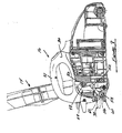
- Figure 2 is a rear perspective view of a portion of the upright handle about to be engaged with the powerhead, and illustrating the handle correctly orientated or insertion into the recesses in the powerhead;
- Figure 3 is a side perspective view of the powerhead illustrating one of the recesses
- Figure 4 is an enlarged perspective view of circled area 4 in Figure 3 showing the recess in greater detail;
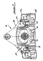
- Figure 5 is a plan view of just the powerhead
- Figure 6 is a perspective view of the foot actuated release lever
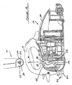
- Figure 7 is a cross-sectional view of the powerhead taken in accordance with section line 7-7 in Figure 5;
- Figure 8 is a side cross-sectional view of the powerhead taken in accordance with section line 8-8 in Figure _, showing the upright handle correctly engaged with the recess of the powerhead;
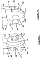
- Figure 9 is an enlarged front perspective view of one of the attachment portions of the upright handle
- Figure 10 is an enlarged rear perspective view of the attachment portion of Figure 9;
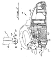
- Figure 11 is a side cross-section view of the powerhead with the upright handle orientated correctly for insertion in the recess, and about to be lowered into the recess;
- Figure 12 is a view of the powerhead of Figure 11 but with the upright handle orientated incorrectly (i.e., 180 degrees turned, or backwards) from the orientation it needs to be to be inserted and latched to the powerhead;
- Figure 13 is a right-hand perspective view of a powerhead adapted for use with an alternative preferred latching mechanism of the present invention
- Figure 14 is a left-hand perspective view of the powerhead of Figure 13;
- Figure 15 is a perspective view of just the handle of the vacuum cleaner used with the powerhead of Figure 13;
- Figure 16 is a side cross-sectional view of a portion of a handle incorporating an alternative latching structure adapted to be used with the powerhead of Figure 13;
- Figure 17 is a view of the handle of Figure 15 latched to securing post of the powerhead of Figure 15.
- the vacuum cleaner 10 generally includes an upright handle assembly 14 and a powerhead 16.
- the handle 14 includes an upper handle portion 18 and a lower end 20.
- the lower end 20 includes a pair of arm portions 22 forming a "fork”.
- Lowermost ends 24 of each arm portion 22 include an attachment portion 26.
- Attachment portions 26 engage within a pair of recesses 28 formed in a housing 30 of the powerhead 16.
- the attachment portions 26, in cooperation with the recesses 28, form two components of the latching mechanism 12 and enable the handle 14 to be detachably secured to the powerhead 16.
- the handle 14 is attached to the powerhead, as shown in Figure 1, to allow the user to maneuver the powerhead 16 over a surface being cleaned.
- attachment portions 26 could just as easily be formed on the powerhead 16 and the recesses formed at the arm portions 22.
- the majority of the components of the latching mechanism 12 may be carried on the handle 14.
- the powerhead 16 also can be used apart from the handle 14 as an independent cleaning tool to clean areas such as stairs, within closets, and other like areas where maneuvering of the powerhead 16 via the handle 14 would be awkward or impossible.
- the housing 30 of the powerhead 16 incorporates an integrally formed handle 31 for allowing the user to maneuver the powerhead 16 with a single hand over a surface being cleaned.
- the housing also incorporates a foot actuated release lever 32.
- the release lever 32 forms the third component of the latching mechanism 12 and will be described more fully in the following paragraphs. Briefly, however, engaging the release lever 32 allows the handle 14 to be quickly and easily detached from the powerhead 16 without the need for any external tools, and also without the need for complicated disassembly procedures.
- the upright handle 14 is also shown as incorporating a tool supporting area 34 for holding a plurality of cleaning attachments.
- cleaning attachments may include a crevice cleaning tool 36, an auxiliary hose length 38 and a brush attachment 40. While these components are not essential to the operation of the latching mechanism 12, they have been illustrated to further highlight that the latching mechanism 12 does not interfere with, or limit, the use of the handle 14 in supporting such well known cleaning attachments.
- Each recess 28 in the housing 30 of the powerhead 16 can be seen in greater detail.
- Each recess 28 includes an arcuate shoulder 42 which receives the attachment portion 26 at the end of each arm portion 22 of the upright handle 14.
- An opening 44 allows part of the attachment portion 26, to be described momentarily, to project transversely into the housing,
- An upper shoulder 46 cooperates with its associated attachment portion 26 to limit forward movement of the handle 14 to essentially the position shown in Figure 1.
- the release lever 32 includes a pair of spaced apart latching arms 48 depending from a foot pedal portion 50.
- a mounting post 52 projects transversely of each latching arm 48.
- Each latching arm 48 has an arcuate profile for engaging with a portion of its associated attachment portion 26.
- the housing 30 of the powerhead 16 can be seen to include a pair of internal support surfaces 54 and 55 for supporting the mounting post 52 for rotational movement.
- the housing 16 is comprised of an upper housing section 16a, a lower housing section 16b, and the release lever 32 is between the support surfaces 54 and 55 of the housing sections 16b and 16a, respectively, of the lower housing section 16b during assembly of the powerhead 16.
- the mounting posts 52 are trapped between the support surfaces 54 and 55 but permit rotational movement of the mounting posts 52.
- the housing 30 can also be seen to include a coil spring 56 supported within a recess 58 of a release lever stop member 60.
- the release lever stop member 60 limits downward movement of the release lever 32.
- the coil spring 56 provides a continuous biasing force to maintain the release lever 32 in its latched position as shown in Figure 8.
- An upper end of the coil spring 56 rests within a pocket 62 so that the upper end cannot shift laterally when the release lever 32 is depressed or released.
- Each attachment portion 26 includes a circumferential base portion 66 which projects outwardly slightly of a lowermost area 68 of the arm portion 22.
- the base portion 66 has a beveled edge 70 and forms a notch 72 near its upper distal end.
- the notch 72 has a flat surface 74 which limits forward pivoting movement of the handle 14 to the position shown in Figure 1.
- the base portion 26 further includes a generally D-shaped mounting post 80 projecting transversely thereof.
- the "D" shape is formed by a flat surface 82 on the mounting post 80 which faces rearwardly (as shown in Figure 8) when the handle 14 is installed on the powerhead 16.
- the handle 14 is a two-piece, clamshell-like construction which comprises sections 14a and 14b.
- An opening 85 is formed in a peripheral edge 87 of section 14a to accommodate a fastener, such as a threaded screw, which engages within a blind hole (not shown) in section 14b to help hold the two sections together.
- the mounting post 82 of each attachment portion 26 seats within an associated one of the openings 44 and the recesses 28 when the handle 14 is correctly installed in the recesses 28.
- the D shape of the mounting posts 80 ensures this, preventing the mounting posts 80 from being fully seated within the openings 44 if the handle 14 is orientated 180° from its correct orientation.
- the flat surface 82 only permits the attachment portions 26 of the handle 14 to be fully inserted in the recesses 28 when the handle 14 is correctly orientated. If the handle is incorrectly orientated, meaning that the flat surfaces 82 of the mounting posts 80 are facing forwardly as shown in Figure 12, then the mounting posts will not be able to properly latch within the recesses 28. This is because even with the release lever 32 urged into its fully counterclockwise most position, as shown in Figure 11, there will not be sufficient clearance between a forwardmost edge 86 of the latching arm 48 and a wall portion 88 ( Figure 11) in the housing 30 to permit the mounting post 80 to clear the forwardmost edge 86 of the latching arm. Thus, the user would be instantly apprised that the handle 14 is not in the correct orientation because the attachment portions 26 will not be able to be latched in the recesses 28.
- the circumferential shape of the base portion 66 provides further advantage that it prevents the attachment portions 26 from being inadvertently lifted out of the recesses 28 when the handle 14 is in use, and therefore not in a perfectly upright orientation. Therefore, as an example, when the handle is in the position shown in Figure 8, even if the release lever 32 is depressed, there will not be sufficient clearance between the forwardmost edge 86 of the latching arm 48 and the interior wall portion 88 to allow the mounting post 80 to be lifted past the forwardmost edge of the latching arm. Thus, to remove the handle 14 the user must first place the handle in the upright orientation shown in Figures 1 and 11, then depress the release pedal 32, and then lift upwardly on the handle 14.
- the vacuum cleaner 100 is comprised of a powerhead 102 and a detachable upright handle 104.
- a latching mechanism 106 is carried by a lower end 108 of the handle 104 rather than by the powerhead 102, in contrast to the vacuum cleaner 10 of Figure 1.
- a pair of mounting posts 110 formed on a housing 112 adjacent recesses 114 on the housing 112 operate in cooperation with the latching mechanism 106, which is disposed within each arm 116 at the lower end 108 of the handle 104.
- a hand actuatable release member 120 is mounted on the handle 104.
- the release member 120 is moveable up and down.
- the lower end 108 of the handle 104 also includes a V-shaped groove 122 at each arm 116.
- the latching mechanism 106 includes a latching lever 124 that is pivotally mounted on a boss portion 126 and spring biased toward a release position (as shown in Figure 16) by a spring 128.
- a stop member 130 limits rotational movement of the latching lever 124 in the counterclockwise direction.
- a slider 132 has a head portion 133 which rests on an upper surface 134 of the latching lever 124.
- An upper end of the slider 132 includes an opening 136 which is coupled to a cable 138.
- the opposite end of the cable 138 is coupled to the release member 120.
- a spring 140 biases the slider 132 downwardly in the drawing of Figures 16 and 17.
- the head portion 133 of the slider 132 is guided between internal walls 142 and 144 of the handle 104 during vertical movement.
- each latching lever 124 contacts its associated mounting post 110.
- the latching lever 124 is urged clockwise against the biasing force of spring 128 as the latching lever fully engages its associated mounting post 110.
- the upper surface 134 of the latching lever 124 moves laterally of the head portion 133 of the slider 132, which allows the head portion to be urged by the spring 140 down into the position shown in Figure 17. In this position the latching lever 124 is latched to the mounting post 110 but can still be rotated around the mounting post.
- the user lifts up on the release member 120 which lifts the slider up against the biasing force of spring 140 into the position shown in Figure 16.
- the spring 128 urges the latching lever 124 counterclockwise into the position shown in Figure 16. The latching lever 124 will be held in this position after the user releases the release member 120.
- the latching mechanism of the present invention thus provides a convenient and easy to operate means for allowing a user to quickly and easily attach and detach the upright handle from the powerhead when needed. Importantly, no external tools or complicated disassembly or reassembly procedures are required.
- the latching of the handle to the powerhead is further accomplished with a minimum number of additional component parts being required within the powerhead. Thus, the latching mechanism does not add significantly to the weight or cost of the vacuum cleaner nor require modifications to the suction airflow path within the powerhead.
Landscapes
- Engineering & Computer Science (AREA)
- Mechanical Engineering (AREA)
- Electric Vacuum Cleaner (AREA)
Abstract
Description
- This invention relates to vacuum cleaners, and more particularly to an upright vacuum cleaner having an upright handle which can be readily detached from a powerhead of the vacuum cleaner, and further which includes structure which prevents the handle from being inadvertently attached in a backward orientation on the powerhead.
- Vacuum cleaner assemblies are used in a wide variety of cleaning applications to clean carpets, upholstered furniture, and other articles. One specific type of upright vacuum cleaner is the "upright" type. This form of vacuum cleaner typically includes a powerhead unit which incorporates a motor for driving a fan. The fan generates a suction airflow for drawing in dust and dirt particles from a surface being cleaned. A filter assembly filters the dust and dirt particles from the ingested airstream. An upright handle is secured to the powerhead for allowing the user to maneuver the powerhead over a work surface when the vacuum cleaner is used in an upright cleaning mode.
- In the event the powerhead is capable of being used without the upright handle, such as with a single hand of the user, then it becomes necessary, and desirable, for the upright handle to be easily removed (i.e., detached) from the powerhead. Preferably, such detachment is accomplished without the need for any external tools such as screwdrivers, pliers, etc., which would complicate the process of detaching the handle in addition to adding significant inconvenience for the operator when the handle is to be detached.
- Accordingly, for those upright vacuum cleaners having a powerhead intended to be used in some cleaning applications without an upright handle attached to the powerhead, there is a need for a latching mechanism which permits a user to quickly and easily detach an upright handle secured to the powerhead without the need for any external tools, and without the need for complicated disassembly procedures. There is further a need for a latching mechanism which allows an upright handle to be resecured to a powerhead in one quick, easy to perform, motion and without the need for any external tools, and also which prevents the user from damaging the handle and/or the powerhead by coupling the handle to the powerhead in a backward orientation.
- The above and other objects are provided by a vacuum cleaner having an upright handle which includes a latching mechanism in accordance with a preferred embodiment of the present invention. The latching mechanism generally includes an attachment portion formed at a lower end of an upright handle and a cooperating recess formed in a housing of an electric powerhead. Together, the upright handle and the powerhead form an upright vacuum cleaner when the handle is secured to the powerhead.
- In one preferred form, the upright handle includes a pair of arms forming a fork. An attachment portion is formed at a lower end of each of the arms. The powerhead includes at least one recess, and more preferably a pair of recesses spaced apart in accordance with the spacing of the attachment portions. The housing of the powerhead also carries a latching arm. In one preferred form the latching arm forms a portion of a foot operated release lever which incorporates a pair of the latching arms spaced apart in accordance with the spacing of the recesses. The latching arms are urged into a latched position, relative to the recesses, by a biasing member.
- When the upright handle is to be installed on the powerhead, the user aligns the arms of the handle over the recesses and lowers the attachment portions on each arm into the recesses. As the attachment portions are lowered into the recesses they engage with the latching arms to automatically latch the attachment portions within the recess. In this condition the handle can be moved pivotally relative to the powerhead without being inadvertently detached therefrom.
- When it is desired to detach the upright handle from the powerhead, the user merely engages the foot actuated release lever and then, while holding the release lever engaged, lifts up on the upright handle to pull the attachment portions up out of the recesses. Accordingly, no tools or complicated disassembly procedures are required to detach the handle from the powerhead. Attachment and detachment of the handle each occur with a single linear motion of the handle. Advantageously, the attachment portions and the recess include cooperating structure which serves to key the attachment portions to the recesses. This prevents the user from attaching the handle in an incorrect orientation, which in turn helps to alert the user that the handle is incorrectly orientated. In this manner the user will be less apt to try and "force" the handle into engagement with the powerhead when the handle is incorrectly orientated, thus averting possible damage to the handle and/or the powerhead.
- Further areas of applicability of the present invention will become apparent from the detailed description provided hereinafter. It should be understood that the detailed description and specific examples, while indicating the preferred embodiment of the invention, are intended for purposes of illustration only and are not intended to limit the scope of the invention.
- The present invention will become more fully understood from the detailed description and the accompanying drawings, wherein:
- Figure 1 is a perspective view of a vacuum cleaner incorporating the latching mechanism in accordance with a preferred embodiment of the present invention;
- Figure 2 is a rear perspective view of a portion of the upright handle about to be engaged with the powerhead, and illustrating the handle correctly orientated or insertion into the recesses in the powerhead;
- Figure 3 is a side perspective view of the powerhead illustrating one of the recesses;
- Figure 4 is an enlarged perspective view of circled
area 4 in Figure 3 showing the recess in greater detail; - Figure 5 is a plan view of just the powerhead;
- Figure 6 is a perspective view of the foot actuated release lever;
- Figure 7 is a cross-sectional view of the powerhead taken in accordance with section line 7-7 in Figure 5;
- Figure 8 is a side cross-sectional view of the powerhead taken in accordance with section line 8-8 in Figure _, showing the upright handle correctly engaged with the recess of the powerhead;
- Figure 9 is an enlarged front perspective view of one of the attachment portions of the upright handle;
- Figure 10 is an enlarged rear perspective view of the attachment portion of Figure 9;
- Figure 11 is a side cross-section view of the powerhead with the upright handle orientated correctly for insertion in the recess, and about to be lowered into the recess;
- Figure 12 is a view of the powerhead of Figure 11 but with the upright handle orientated incorrectly (i.e., 180 degrees turned, or backwards) from the orientation it needs to be to be inserted and latched to the powerhead;
- Figure 13 is a right-hand perspective view of a powerhead adapted for use with an alternative preferred latching mechanism of the present invention;
- Figure 14 is a left-hand perspective view of the powerhead of Figure 13;
- Figure 15 is a perspective view of just the handle of the vacuum cleaner used with the powerhead of Figure 13;
- Figure 16 is a side cross-sectional view of a portion of a handle incorporating an alternative latching structure adapted to be used with the powerhead of Figure 13; and
- Figure 17 is a view of the handle of Figure 15 latched to securing post of the powerhead of Figure 15.
- The following description of the preferred embodiment(s) is merely exemplary in nature and is in no way intended to limit the invention, its application, or uses.
- Referring to Figures 1 and 2, there is shown a
vacuum cleaner 10 incorporating alatching mechanism 12 in accordance with a preferred embodiment of the present invention. Thevacuum cleaner 10 generally includes anupright handle assembly 14 and apowerhead 16. Thehandle 14 includes anupper handle portion 18 and alower end 20. Thelower end 20 includes a pair ofarm portions 22 forming a "fork".Lowermost ends 24 of eacharm portion 22 include anattachment portion 26.Attachment portions 26 engage within a pair ofrecesses 28 formed in ahousing 30 of thepowerhead 16. Theattachment portions 26, in cooperation with therecesses 28, form two components of thelatching mechanism 12 and enable thehandle 14 to be detachably secured to thepowerhead 16. Thus, when thevacuum cleaner 10 is to be used in an upright cleaning mode, thehandle 14 is attached to the powerhead, as shown in Figure 1, to allow the user to maneuver thepowerhead 16 over a surface being cleaned. - It will be appreciated that the
attachment portions 26 could just as easily be formed on thepowerhead 16 and the recesses formed at thearm portions 22. Alternatively, as will be described more fully in the following paragraphs, the majority of the components of thelatching mechanism 12 may be carried on thehandle 14. - The
powerhead 16 also can be used apart from thehandle 14 as an independent cleaning tool to clean areas such as stairs, within closets, and other like areas where maneuvering of thepowerhead 16 via thehandle 14 would be awkward or impossible. To this end, thehousing 30 of thepowerhead 16 incorporates an integrally formedhandle 31 for allowing the user to maneuver thepowerhead 16 with a single hand over a surface being cleaned. To allow thepowerhead 16 to be used without thehandle 14, the housing also incorporates a foot actuatedrelease lever 32. Therelease lever 32 forms the third component of thelatching mechanism 12 and will be described more fully in the following paragraphs. Briefly, however, engaging therelease lever 32 allows thehandle 14 to be quickly and easily detached from thepowerhead 16 without the need for any external tools, and also without the need for complicated disassembly procedures. - Referring further to Figure 1, the
upright handle 14 is also shown as incorporating atool supporting area 34 for holding a plurality of cleaning attachments. Such cleaning attachments may include acrevice cleaning tool 36, anauxiliary hose length 38 and abrush attachment 40. While these components are not essential to the operation of thelatching mechanism 12, they have been illustrated to further highlight that thelatching mechanism 12 does not interfere with, or limit, the use of thehandle 14 in supporting such well known cleaning attachments. - Referring to Figures 2-5, the
recesses 28 in thehousing 30 of thepowerhead 16 can be seen in greater detail. Eachrecess 28 includes anarcuate shoulder 42 which receives theattachment portion 26 at the end of eacharm portion 22 of theupright handle 14. An opening 44 allows part of theattachment portion 26, to be described momentarily, to project transversely into the housing, Anupper shoulder 46 cooperates with its associatedattachment portion 26 to limit forward movement of thehandle 14 to essentially the position shown in Figure 1. - Referring to Figures 6 and 7, the foot actuated
release lever 32 and its mounting within thepowerhead 16 can be seen in greater detail. Therelease lever 32 includes a pair of spaced apart latchingarms 48 depending from afoot pedal portion 50. A mountingpost 52 projects transversely of each latchingarm 48. Each latchingarm 48 has an arcuate profile for engaging with a portion of its associatedattachment portion 26. - Referring specifically to Figure 7, the
housing 30 of thepowerhead 16 can be seen to include a pair of internal support surfaces 54 and 55 for supporting the mountingpost 52 for rotational movement. Thehousing 16 is comprised of anupper housing section 16a, a lower housing section 16b, and therelease lever 32 is between the support surfaces 54 and 55 of thehousing sections 16b and 16a, respectively, of the lower housing section 16b during assembly of thepowerhead 16. When theupper housing section 16a is assembled to the lower housing section 16b, the mountingposts 52 are trapped between the support surfaces 54 and 55 but permit rotational movement of the mounting posts 52. - With reference to Figure 8, the
housing 30 can also be seen to include acoil spring 56 supported within arecess 58 of a releaselever stop member 60. The releaselever stop member 60 limits downward movement of therelease lever 32. Thecoil spring 56 provides a continuous biasing force to maintain therelease lever 32 in its latched position as shown in Figure 8. An upper end of thecoil spring 56 rests within apocket 62 so that the upper end cannot shift laterally when therelease lever 32 is depressed or released. - Referring now to Figure 9, one of the
attachment portions 26 can be seen. Eachattachment portion 26 includes a circumferential base portion 66 which projects outwardly slightly of alowermost area 68 of thearm portion 22. The base portion 66 has abeveled edge 70 and forms anotch 72 near its upper distal end. Thenotch 72 has aflat surface 74 which limits forward pivoting movement of thehandle 14 to the position shown in Figure 1. - With further reference to Figures 9 and 10, the
base portion 26 further includes a generally D-shaped mountingpost 80 projecting transversely thereof. The "D" shape is formed by aflat surface 82 on the mountingpost 80 which faces rearwardly (as shown in Figure 8) when thehandle 14 is installed on thepowerhead 16. Thehandle 14 is a two-piece, clamshell-like construction which comprisessections 14a and 14b. Anopening 85 is formed in aperipheral edge 87 ofsection 14a to accommodate a fastener, such as a threaded screw, which engages within a blind hole (not shown) in section 14b to help hold the two sections together. - With further reference to Figures 4, 10 and 11, the mounting
post 82 of eachattachment portion 26 seats within an associated one of the openings 44 and therecesses 28 when thehandle 14 is correctly installed in therecesses 28. The D shape of the mountingposts 80 ensures this, preventing the mountingposts 80 from being fully seated within the openings 44 if thehandle 14 is orientated 180° from its correct orientation. - Referring now to Figures 8 and 11, when the
handle 14 is to be attached to thepowerhead 16, and is orientated correctly (i.e., withflat surfaces 82 facing rearwardly) as shown in Figure 11, theattachment portion 26 at the lower end of eacharm 22 may be dropped into its associatedrecess 28 and the mountingpost 80 will abut a taperededge 84 of arib 86 of the latching arm. As thehandle 14 is lowered further, the mountingpost 80 will urge the latchingarm 48 counterclockwise in the drawing of Figure 11. As the mountingpost 80 is lowered further and completely clears the latchingarm 48, the latching arm will be urged by the biasing spring 56 (Figure 8) clockwise to latch over the mountingpost 80. At this point thehandle 14 will not be removable from thepowerhead 16 unless therelease lever 32 is depressed into engagement against thestop member 60. Thus, attachment of thehandle 14 to thepowerhead 16 does not require the user to depress therelease lever 32, but releasing of thehandle 14 does require such a depressing of the release lever before the handle can be lifted up and detached from thepowerhead 16. - It is an important feature of the present invention that the
flat surface 82 only permits theattachment portions 26 of thehandle 14 to be fully inserted in therecesses 28 when thehandle 14 is correctly orientated. If the handle is incorrectly orientated, meaning that theflat surfaces 82 of the mountingposts 80 are facing forwardly as shown in Figure 12, then the mounting posts will not be able to properly latch within therecesses 28. This is because even with therelease lever 32 urged into its fully counterclockwise most position, as shown in Figure 11, there will not be sufficient clearance between aforwardmost edge 86 of the latchingarm 48 and a wall portion 88 (Figure 11) in thehousing 30 to permit the mountingpost 80 to clear theforwardmost edge 86 of the latching arm. Thus, the user would be instantly apprised that thehandle 14 is not in the correct orientation because theattachment portions 26 will not be able to be latched in therecesses 28. - The circumferential shape of the base portion 66 provides further advantage that it prevents the
attachment portions 26 from being inadvertently lifted out of therecesses 28 when thehandle 14 is in use, and therefore not in a perfectly upright orientation. Therefore, as an example, when the handle is in the position shown in Figure 8, even if therelease lever 32 is depressed, there will not be sufficient clearance between theforwardmost edge 86 of the latchingarm 48 and theinterior wall portion 88 to allow the mountingpost 80 to be lifted past the forwardmost edge of the latching arm. Thus, to remove thehandle 14 the user must first place the handle in the upright orientation shown in Figures 1 and 11, then depress therelease pedal 32, and then lift upwardly on thehandle 14. - Referring now to Figures 13-17, a
vacuum cleaner 100 in accordance with an alternative preferred embodiment of the present invention is shown. Thevacuum cleaner 100 is comprised of apowerhead 102 and a detachableupright handle 104. Alatching mechanism 106 is carried by alower end 108 of thehandle 104 rather than by thepowerhead 102, in contrast to thevacuum cleaner 10 of Figure 1. A pair of mountingposts 110 formed on ahousing 112adjacent recesses 114 on thehousing 112 operate in cooperation with thelatching mechanism 106, which is disposed within eacharm 116 at thelower end 108 of thehandle 104. - Referring specifically to Figure 15, a hand
actuatable release member 120 is mounted on thehandle 104. Therelease member 120 is moveable up and down. Thelower end 108 of thehandle 104 also includes a V-shapedgroove 122 at eacharm 116. - With reference to Figures 16 and 17, one of the latching
mechanisms 106 can be seen. Thelatching mechanism 106 includes a latchinglever 124 that is pivotally mounted on aboss portion 126 and spring biased toward a release position (as shown in Figure 16) by aspring 128. Astop member 130 limits rotational movement of the latchinglever 124 in the counterclockwise direction. - With further reference to figures 16 and 17, a
slider 132 has ahead portion 133 which rests on anupper surface 134 of the latchinglever 124. An upper end of theslider 132 includes anopening 136 which is coupled to acable 138. The opposite end of thecable 138 is coupled to therelease member 120. Aspring 140 biases theslider 132 downwardly in the drawing of Figures 16 and 17. Thehead portion 133 of theslider 132 is guided betweeninternal walls handle 104 during vertical movement. - When the
handle 104 is to be latched to the mountingposts 110 of thepowerhead 102, the user positions thelower end 108 of the handle such that the V-shapedgrooves 122 are over the mounting posts. The user then lowers thehandle 104 and athumb portion 146 of each latchinglever 124 contacts its associated mountingpost 110. As thehandle 104 is lowered further, the latchinglever 124 is urged clockwise against the biasing force ofspring 128 as the latching lever fully engages its associated mountingpost 110. As this movement occurs, theupper surface 134 of the latchinglever 124 moves laterally of thehead portion 133 of theslider 132, which allows the head portion to be urged by thespring 140 down into the position shown in Figure 17. In this position the latchinglever 124 is latched to the mountingpost 110 but can still be rotated around the mounting post. - To detach the
handle 104, the user lifts up on therelease member 120 which lifts the slider up against the biasing force ofspring 140 into the position shown in Figure 16. As soon as thehead portion 133 clears the upper end of the latchinglever 124, thespring 128 urges the latchinglever 124 counterclockwise into the position shown in Figure 16. The latchinglever 124 will be held in this position after the user releases therelease member 120. - The latching mechanism of the present invention thus provides a convenient and easy to operate means for allowing a user to quickly and easily attach and detach the upright handle from the powerhead when needed. Importantly, no external tools or complicated disassembly or reassembly procedures are required. The latching of the handle to the powerhead is further accomplished with a minimum number of additional component parts being required within the powerhead. Thus, the latching mechanism does not add significantly to the weight or cost of the vacuum cleaner nor require modifications to the suction airflow path within the powerhead.
- Those skilled in the art can now appreciate from the foregoing description that the broad teachings of the present invention can be implemented in a variety of forms. Therefore, while this invention has been described in connection with particular examples thereof, the true scope of the invention should not be so limited since other modifications will become apparent to the skilled practitioner upon a study of the drawings, specification and following claims.
Claims (14)
- A vacuum cleaner comprising:wherein said second securing structure can be released from said first securing structure by movement of said release lever to permit said upright handle to be detached from said powerhead by engaging said release member and separating said upright handle from said powerhead.a powerhead for generating a suction airflow;said powerhead having a first securing structure for engaging with a portion of a detachable handle;a detachable upright handle for maneuvering said powerhead over a surface being cleaned, said upright handle having a second securing structure for automatically engaging within said first securing structure when said handle portion is attached to said powerhead;a release member associated with one of said securing structures and manually engageable by a user; and
- The vacuum cleaner of claim 1, wherein said first securing structure comprises a recess formed in said powerhead and said release member.
- The vacuum cleaner of claim 1, wherein said second securing structure comprises an attachment portion formed at a lower end of said upright handle, and wherein said release member is associated with said first securing structure to engage said attachment portion when said upright handle is secured to said powerhead.
- The vacuum cleaner of claim 3, wherein said release member is pivotally mounted on said powerhead such that a portion of said release member projects from said powerhead and is readily engageable by said user;
wherein a biasing element is used to bias said release member into a normally latched position; and
wherein a portion of said release member automatically engages said attachment portion when said lower end of said upright handle is urged into engagement with said release member. - A vacuum cleaner comprising:wherein said securing portion can be released from said recess by manual movement of said release lever to permit said upright handle to be detached from said powerhead.a powerhead for generating a suction airflow;said powerhead having at least one recess formed in a housing thereof and a manually engageable release lever, said release lever being supported from said housing and biased via a biasing force toward a latched position, and movable against said biasing force to said open position;an upright handle for maneuvering said powerhead over a surface being cleaned, said upright handle having a lower end including an attachment portion, said attachment portion including a securing portion for automatically engaging within said recess when said attachment portion is lowered into said recess; and
- The vacuum cleaner of claim 5 wherein said attachment portion includes structure keying it to said recess such that said upright handle cannot be installed in a backward orientation by a user.
- The vacuum cleaner of claim 5, wherein said release lever includes a latching arm having an angled upper surface for engaging with said securing portion when said attachment portion is lowered into said recess and urging said release lever away from said recess, to thereby permit said latching arm to automatically engage said securing portion when said securing portion is fully seated within said recess.
- The vacuum cleaner of claim 7, wherein said attachment portion includes a rib, and wherein said recess comprises a shoulder for interfering with rib to prevent said upright handle from being inadvertently installed in a backward orientation on said powerhead by a user.
- A vacuum cleaner comprising:wherein said securing post is automatically engageable with said latching arm in said latched position within said recess when said attachment portion is lowered into said recess; anda powerhead for generating a suction airflow;said powerhead having at least one recess formed in a housing thereof and a foot actuated lever having a latching arm, said lever being pivotally supported from said housing and biased toward a latched position, and movable against said biasing force to said open position;an upright handle having a lower end including an attachment portion, said attachment portion including a securing post for engaging within said recess; and
wherein said securing post is released from said powerhead when said foot actuated lever is engaged by a user, thereby removing said latching arm from engagement with said securing post. - The vacuum cleaner of claim 9, wherein said securing post comprises structure keying it to said recess such that said handle is prevented from being secured to said powerhead in a backwards orientation.
- The vacuum cleaner of claim 10, wherein said attachment portion comprises a raised shoulder, and wherein said raised shoulder interferes with a portion of said recess if said handle is inserted in said backward orientation to prevent latching of said attachment portion within said recess.
- The vacuum cleaner of claim 9, wherein said latching arm includes an angled upper surface for enabling said attachment portion to automatically urge said latching arm away from said recess as said attachment portion contacts said angled upper surface while being lowered into said recess.
- A vacuum cleaner comprising:a powerhead for generating a suction airflow;said powerhead having at least one recess formed in a housing thereof and a foot actuated lever having a latching arm, said lever being pivotally supported from said housing;a biasing member for biasing said foot actuated lever toward a latched position, said lever being movable against said biasing force to an unlatched position;an upright handle having a lower end including an attachment portion, said attachment portion including a securing post for engaging within said recess;said securing post being automatically engageable with said latching arm in said latched position within said recess when said attachment portion is lowered into said recess;said securing post being released from said powerhead when said foot actuated lever is engaged by a user, thereby removing said latching arm from engagement with said securing post; andsaid attachment portion and said recess including cooperating structure to key said attachment portion to said recess such that said upright handle cannot be inadvertently installed in a backward orientation on said powerhead.
- The vacuum cleaner of claim 13, wherein said latching arm includes an angled upper end which enables said attachment portion to contact and urge said latching arm away from said recess as said attachment portion is lowered into said recess, whereupon said latching arm snaps into latching engagement with said securing portion when said attachment portion is substantially fully seated within said recess.
Applications Claiming Priority (2)
| Application Number | Priority Date | Filing Date | Title |
|---|---|---|---|
| US09/886,963 US6574831B2 (en) | 2001-06-21 | 2001-06-21 | Upright vacuum cleaner having detachable upright handle |
| US886963 | 2001-06-21 |
Publications (2)
| Publication Number | Publication Date |
|---|---|
| EP1269904A1 true EP1269904A1 (en) | 2003-01-02 |
| EP1269904B1 EP1269904B1 (en) | 2007-11-14 |
Family
ID=25390158
Family Applications (1)
| Application Number | Title | Priority Date | Filing Date |
|---|---|---|---|
| EP02445080A Expired - Lifetime EP1269904B1 (en) | 2001-06-21 | 2002-06-20 | Upright vacuum cleaner having detachable upright handle |
Country Status (9)
| Country | Link |
|---|---|
| US (1) | US6574831B2 (en) |
| EP (1) | EP1269904B1 (en) |
| JP (1) | JP4149747B2 (en) |
| CN (1) | CN100431462C (en) |
| AT (1) | ATE377998T1 (en) |
| AU (1) | AU784227B2 (en) |
| CA (1) | CA2391177C (en) |
| DE (1) | DE60223452T2 (en) |
| ES (1) | ES2294094T3 (en) |
Cited By (2)
| Publication number | Priority date | Publication date | Assignee | Title |
|---|---|---|---|---|
| CN101732010B (en) * | 2008-11-18 | 2013-08-21 | 株式会社牧田 | Handle construction and dust extractor |
| GB2603523A (en) * | 2021-02-08 | 2022-08-10 | Numatic Int Ltd | Vacuum cleaner |
Families Citing this family (47)
| Publication number | Priority date | Publication date | Assignee | Title |
|---|---|---|---|---|
| DE10336829B4 (en) * | 2003-08-11 | 2013-04-11 | BSH Bosch und Siemens Hausgeräte GmbH | Vacuum cleaner with a swivel handle |
| US7377007B2 (en) * | 2004-03-02 | 2008-05-27 | Bissell Homecare, Inc. | Vacuum cleaner with detachable vacuum module |
| CN101262807B (en) * | 2005-01-18 | 2011-11-16 | 伊莱克斯家用产品有限公司 | Vacuum cleaner with collapsible handle |
| CN1853554B (en) * | 2005-04-29 | 2011-01-26 | 光荣电业公司 | electric cleaning sweeper |
| USD544158S1 (en) * | 2006-01-18 | 2007-06-05 | Electrolux Home Care Products, Ltd. | Vacuum cleaner base |
| JP2010502372A (en) * | 2006-09-08 | 2010-01-28 | シンフォニー メディカル, インコーポレイテッド | Intramyocardial patterning for the treatment of regional abnormalities of the heart |
| CN101657134B (en) | 2006-12-12 | 2013-05-08 | Gbd公司 | Multi-Pillar Cleaning Head |
| EP1955631B1 (en) * | 2007-02-12 | 2010-11-24 | Black & Decker, Inc. | Vacuum cleaners |
| US20100199969A1 (en) * | 2009-02-10 | 2010-08-12 | Edmund Chan | Pool protection and solar heating cover |
| CA2674761C (en) | 2009-03-13 | 2016-10-04 | G.B.D. Corp. | Surface cleaning apparatus with different cleaning configurations |
| US9226633B2 (en) | 2009-03-13 | 2016-01-05 | Omachron Intellectual Property Inc. | Surface cleaning apparatus |
| US9392916B2 (en) | 2009-03-13 | 2016-07-19 | Omachron Intellectual Property Inc. | Surface cleaning apparatus |
| CA2674376A1 (en) | 2009-03-13 | 2010-09-13 | G.B.D. Corp. | Surface cleaning apparatus with different cleaning configurations |
| US11612288B2 (en) | 2009-03-13 | 2023-03-28 | Omachron Intellectual Property Inc. | Surface cleaning apparatus |
| US9591953B2 (en) | 2009-03-13 | 2017-03-14 | Omachron Intellectual Property Inc. | Surface cleaning apparatus |
| US9480373B2 (en) | 2009-03-13 | 2016-11-01 | Omachron Intellectual Property Inc. | Surface cleaning apparatus |
| US9427122B2 (en) | 2009-03-13 | 2016-08-30 | Omachron Intellectual Property Inc. | Surface cleaning apparatus |
| US9198551B2 (en) | 2013-02-28 | 2015-12-01 | Omachron Intellectual Property Inc. | Surface cleaning apparatus |
| US20120246866A1 (en) * | 2011-03-28 | 2012-10-04 | Emerson Electric Co. | Support System Adjustable by Like Motion and Method of Use |
| US9282862B2 (en) * | 2011-10-14 | 2016-03-15 | Techtronic Floor Care Technology Limited | Steering assembly for surface cleaning device |
| CN102860789A (en) * | 2012-09-25 | 2013-01-09 | 苏州原点工业设计有限公司 | Vacuum cleaner |
| US9215960B2 (en) | 2013-02-28 | 2015-12-22 | Omachron Intellectual Property Inc. | Surface cleaning apparatus |
| US8943647B1 (en) | 2013-08-09 | 2015-02-03 | Techtronic Floor Care Technology Limited | Vacuum cleaner including a removable handle assembly |
| GB2522668B (en) * | 2014-01-31 | 2017-05-17 | Techtronic Floor Care Tech Ltd | Surface cleaning apparatus |
| US9775481B2 (en) | 2014-12-17 | 2017-10-03 | Omachron Intellectual Property Inc. | All in the head surface cleaning apparatus |
| US10022027B2 (en) | 2014-12-17 | 2018-07-17 | Omachron Intellectual Property Inc. | All in the head surface cleaning apparatus |
| US9901229B2 (en) | 2014-12-17 | 2018-02-27 | Omachron Intellectual Property Inc. | All in the head surface cleaning apparatus |
| US9775480B2 (en) | 2014-12-17 | 2017-10-03 | Omachron Intellectual Property Inc. | All in the head surface cleaning apparatus |
| US9717383B2 (en) | 2014-12-17 | 2017-08-01 | Omachron Intellectual Property Inc. | All in the head surface cleaning apparatus |
| US9668630B2 (en) | 2014-12-17 | 2017-06-06 | Omachron Intellectual Property Inc. | All in the head surface cleaning apparatus |
| US11202544B2 (en) | 2014-12-17 | 2021-12-21 | Omachron Intellectual Property Inc. | All in the head surface cleaning apparatus |
| US9545180B2 (en) | 2014-12-17 | 2017-01-17 | Omachron Intellectual Property Inc. | All in the head surface cleaning apparatus |
| US9883781B2 (en) | 2014-12-17 | 2018-02-06 | Omachron Intellectual Property Inc. | All in the head surface cleaning apparatus |
| US9795264B2 (en) | 2014-12-17 | 2017-10-24 | Omachron Intellectual Property Inc. | All in the head surface cleaning apparatus |
| US9295363B1 (en) | 2014-12-17 | 2016-03-29 | Omachron Intellectual Property Inc. | All in the head surface cleaning apparatus |
| US9775479B2 (en) * | 2014-12-17 | 2017-10-03 | Omachron Intellectual Property Inc. | All in the head surface cleaning apparatus |
| US10357136B2 (en) | 2014-12-17 | 2019-07-23 | Omachron Intellectual Property Inc. | All in the head surface cleaning apparatus |
| US9668624B2 (en) | 2014-12-17 | 2017-06-06 | Omachron Intellectual Property Inc. | All in the head surface cleaning apparatus |
| US11980334B2 (en) | 2017-09-15 | 2024-05-14 | Omachron Intellectual Property Inc. | Surface cleaning apparatus |
| US12459720B2 (en) | 2017-09-15 | 2025-11-04 | Omachron Intellectual Property Inc. | Non-cyclonic momentum separator and a surface cleaning apparatus |
| CN210842843U (en) * | 2018-11-06 | 2020-06-26 | 江苏美的清洁电器股份有限公司 | cleaning device |
| EP3962340B1 (en) | 2019-05-03 | 2024-07-03 | Techtronic Floor Care Technology Limited | Floor cleaner |
| WO2020249186A1 (en) * | 2019-06-11 | 2020-12-17 | Aktiebolaget Electrolux | Vacuum cleaner nozzle |
| USD937513S1 (en) | 2019-09-16 | 2021-11-30 | Techtronic Cordless Gp | Floor cleaner |
| WO2021138122A1 (en) | 2020-01-03 | 2021-07-08 | Techtronic Cordless Gp | Adapter for vacuum cleaner assembly |
| CN113633216A (en) * | 2020-05-11 | 2021-11-12 | 添可智能科技有限公司 | Scrubbing brush and dust catcher |
| CN114843076B (en) * | 2022-05-26 | 2022-11-18 | 深圳市德利泰精密五金制品有限公司 | Additional detachable heat dissipation assembly for transformer |
Citations (4)
| Publication number | Priority date | Publication date | Assignee | Title |
|---|---|---|---|---|
| US1676058A (en) * | 1924-08-29 | 1928-07-03 | Hoover Co | Handle control |
| US3621511A (en) * | 1969-02-24 | 1971-11-23 | Wilbur Webb Selley | Detachable handle device |
| US3897607A (en) * | 1973-03-19 | 1975-08-05 | Bison Mfg Co Inc | Readily removable implement handle |
| US4947512A (en) * | 1988-12-09 | 1990-08-14 | The Scott Fetzer Company | Convertible vacuum cleaner |
Family Cites Families (17)
| Publication number | Priority date | Publication date | Assignee | Title |
|---|---|---|---|---|
| US1918519A (en) * | 1930-07-16 | 1933-07-18 | Clements Mfg Co | Vacuum cleaner |
| US2842788A (en) * | 1956-01-27 | 1958-07-15 | Racine Ind Plant Inc | Carpet scrubbing machine |
| US3608333A (en) | 1968-06-20 | 1971-09-28 | Bison Mfg Co Inc | Vacuum cleaner and power unit |
| DE8224611U1 (en) | 1982-09-01 | 1982-12-09 | Vorwerk & Co Interholding Gmbh, 5600 Wuppertal | HANDLE FOR A HAND VACUUM CLEANER |
| DE8427360U1 (en) * | 1984-09-17 | 1984-12-13 | Progress-Elektrogeräte Mauz & Pfeiffer GmbH & Co, 7000 Stuttgart | HAND VACUUM CLEANER |
| DE8623004U1 (en) | 1986-08-28 | 1986-10-30 | Rowenta-Werke Gmbh, 6050 Offenbach | Support plate for small vacuum cleaners |
| US5014388A (en) | 1989-05-15 | 1991-05-14 | White Consolidated Industries, Inc. | Battery powered vacuum cleaner |
| US5086536A (en) | 1990-05-11 | 1992-02-11 | The Scott Fetzer Company | Convertible vacuum cleaner |
| CA2016600C (en) | 1990-05-11 | 1996-10-22 | John R. Lackner | Convertible vacuum cleaner |
| US5699586A (en) | 1996-01-11 | 1997-12-23 | Black & Decker Inc. | Vacuum cleaner with improved suction inlet |
| US5664285A (en) | 1996-01-11 | 1997-09-09 | Black & Decker Inc. | Vacuum cleaner with combined filter element and collection unit |
| US5671499A (en) | 1996-01-11 | 1997-09-30 | Black & Decker Inc. | Vacuum cleaner with all components in floor traveling head |
| SE506051C2 (en) | 1996-02-16 | 1997-11-03 | Electrolux Ab | Handle attachment |
| US6012200A (en) | 1997-01-10 | 2000-01-11 | Royal Appliance Mfg. Co. | Upright vacuum cleaner |
| GB9726673D0 (en) * | 1997-12-17 | 1998-02-18 | Notetry Ltd | A vacuum cleaner |
| US6317920B1 (en) | 1998-11-30 | 2001-11-20 | Royal Appliance Mfg. Co. | Vacuum cleaner with above-floor cleaning tool |
| CA2292317C (en) | 1999-08-13 | 2004-05-04 | Samsung Kwangju Electronics Co., Ltd. | Stick-type vacuum cleaner |
-
2001
- 2001-06-21 US US09/886,963 patent/US6574831B2/en not_active Expired - Lifetime
-
2002
- 2002-06-20 ES ES02445080T patent/ES2294094T3/en not_active Expired - Lifetime
- 2002-06-20 CA CA2391177A patent/CA2391177C/en not_active Expired - Fee Related
- 2002-06-20 EP EP02445080A patent/EP1269904B1/en not_active Expired - Lifetime
- 2002-06-20 AT AT02445080T patent/ATE377998T1/en not_active IP Right Cessation
- 2002-06-20 DE DE60223452T patent/DE60223452T2/en not_active Expired - Lifetime
- 2002-06-21 JP JP2002181926A patent/JP4149747B2/en not_active Expired - Fee Related
- 2002-06-21 CN CNB021472858A patent/CN100431462C/en not_active Expired - Fee Related
- 2002-06-21 AU AU48907/02A patent/AU784227B2/en not_active Ceased
Patent Citations (4)
| Publication number | Priority date | Publication date | Assignee | Title |
|---|---|---|---|---|
| US1676058A (en) * | 1924-08-29 | 1928-07-03 | Hoover Co | Handle control |
| US3621511A (en) * | 1969-02-24 | 1971-11-23 | Wilbur Webb Selley | Detachable handle device |
| US3897607A (en) * | 1973-03-19 | 1975-08-05 | Bison Mfg Co Inc | Readily removable implement handle |
| US4947512A (en) * | 1988-12-09 | 1990-08-14 | The Scott Fetzer Company | Convertible vacuum cleaner |
Cited By (4)
| Publication number | Priority date | Publication date | Assignee | Title |
|---|---|---|---|---|
| CN101732010B (en) * | 2008-11-18 | 2013-08-21 | 株式会社牧田 | Handle construction and dust extractor |
| GB2603523A (en) * | 2021-02-08 | 2022-08-10 | Numatic Int Ltd | Vacuum cleaner |
| WO2022167785A1 (en) * | 2021-02-08 | 2022-08-11 | Numatic International Limited | Vacuum cleaner |
| GB2603523B (en) * | 2021-02-08 | 2024-08-28 | Numatic Int Ltd | Vacuum cleaner |
Also Published As
| Publication number | Publication date |
|---|---|
| US6574831B2 (en) | 2003-06-10 |
| CN100431462C (en) | 2008-11-12 |
| US20020194699A1 (en) | 2002-12-26 |
| JP2003047580A (en) | 2003-02-18 |
| EP1269904B1 (en) | 2007-11-14 |
| DE60223452T2 (en) | 2008-09-18 |
| ATE377998T1 (en) | 2007-11-15 |
| ES2294094T3 (en) | 2008-04-01 |
| DE60223452D1 (en) | 2007-12-27 |
| CA2391177A1 (en) | 2002-12-21 |
| AU4890702A (en) | 2003-01-02 |
| CA2391177C (en) | 2010-04-20 |
| JP4149747B2 (en) | 2008-09-17 |
| CN1406552A (en) | 2003-04-02 |
| AU784227B2 (en) | 2006-02-23 |
Similar Documents
| Publication | Publication Date | Title |
|---|---|---|
| US6574831B2 (en) | Upright vacuum cleaner having detachable upright handle | |
| CA2413401C (en) | Convertible vacuum cleaner | |
| CA2086374C (en) | Release mechanism for a vacuum hose | |
| EP2289381B1 (en) | Vacuum cleaner accessory tool having a removable brush | |
| US8943647B1 (en) | Vacuum cleaner including a removable handle assembly | |
| EP2048998B1 (en) | Handle assembly for a cleaning appliance | |
| CN1997308B (en) | Handle Assemblies for Cleaning Utensils | |
| US12305683B2 (en) | Connecting structure between power tool and attachment | |
| US20140041149A1 (en) | Vacuum cleaner including a removable canister assembly | |
| EP3030125B1 (en) | Vacuum cleaner including a removable handle assembly | |
| JP5578281B2 (en) | Electric vacuum cleaner | |
| JP4047262B2 (en) | Upright type vacuum cleaner | |
| JP4417758B2 (en) | Vacuum cleaner | |
| JP2006034593A (en) | Electric vacuum cleaner | |
| JP3926788B2 (en) | Electric vacuum cleaner | |
| JP2005312788A (en) | Vacuum cleaner | |
| CN121465429A (en) | Cleaning device | |
| JPH07217957A (en) | Ventilation fan | |
| JP2005318977A (en) | Vacuum cleaner | |
| JP2008022950A (en) | Vacuum cleaner | |
| JP2000083874A (en) | Suction port body and vacuum cleaner using the same | |
| JPH0712205U (en) | Dust collecting nozzle mounting structure for electric tools |
Legal Events
| Date | Code | Title | Description |
|---|---|---|---|
| PUAI | Public reference made under article 153(3) epc to a published international application that has entered the european phase |
Free format text: ORIGINAL CODE: 0009012 |
|
| AK | Designated contracting states |
Kind code of ref document: A1 Designated state(s): AT BE CH CY DE DK ES FI FR GB GR IE IT LI LU MC NL PT SE TR |
|
| AX | Request for extension of the european patent |
Free format text: AL;LT;LV;MK;RO;SI |
|
| RIN1 | Information on inventor provided before grant (corrected) |
Inventor name: PROSPER, JACOB R. Inventor name: MACTAVISH, COREY D. Inventor name: SERGYEYENKO, OLEKSIY P. Inventor name: HUNTER, MURRAY D. Inventor name: SHAVER, DAVID M. |
|
| 17P | Request for examination filed |
Effective date: 20030701 |
|
| AKX | Designation fees paid |
Designated state(s): AT BE CH CY DE DK ES FI FR GB GR IE IT LI LU MC NL PT SE TR |
|
| GRAP | Despatch of communication of intention to grant a patent |
Free format text: ORIGINAL CODE: EPIDOSNIGR1 |
|
| RIN1 | Information on inventor provided before grant (corrected) |
Inventor name: SERGYEYENKO, OLEKSIY P. Inventor name: HUNTER, MURRAY D. Inventor name: PROSPER, JACOB R. Inventor name: SHAVER, DAVID M. Inventor name: MACTAVISH, COREY D. |
|
| GRAS | Grant fee paid |
Free format text: ORIGINAL CODE: EPIDOSNIGR3 |
|
| GRAA | (expected) grant |
Free format text: ORIGINAL CODE: 0009210 |
|
| AK | Designated contracting states |
Kind code of ref document: B1 Designated state(s): AT BE CH CY DE DK ES FI FR GB GR IE IT LI LU MC NL PT SE TR |
|
| REG | Reference to a national code |
Ref country code: GB Ref legal event code: FG4D |
|
| REG | Reference to a national code |
Ref country code: CH Ref legal event code: EP |
|
| REG | Reference to a national code |
Ref country code: IE Ref legal event code: FG4D |
|
| REF | Corresponds to: |
Ref document number: 60223452 Country of ref document: DE Date of ref document: 20071227 Kind code of ref document: P |
|
| REG | Reference to a national code |
Ref country code: SE Ref legal event code: TRGR |
|
| REG | Reference to a national code |
Ref country code: CH Ref legal event code: NV Representative=s name: E. BLUM & CO. AG PATENT- UND MARKENANWAELTE VSP |
|
| REG | Reference to a national code |
Ref country code: ES Ref legal event code: FG2A Ref document number: 2294094 Country of ref document: ES Kind code of ref document: T3 |
|
| ET | Fr: translation filed | ||
| PG25 | Lapsed in a contracting state [announced via postgrant information from national office to epo] |
Ref country code: DK Free format text: LAPSE BECAUSE OF FAILURE TO SUBMIT A TRANSLATION OF THE DESCRIPTION OR TO PAY THE FEE WITHIN THE PRESCRIBED TIME-LIMIT Effective date: 20071114 |
|
| PLBE | No opposition filed within time limit |
Free format text: ORIGINAL CODE: 0009261 |
|
| STAA | Information on the status of an ep patent application or granted ep patent |
Free format text: STATUS: NO OPPOSITION FILED WITHIN TIME LIMIT |
|
| PG25 | Lapsed in a contracting state [announced via postgrant information from national office to epo] |
Ref country code: PT Free format text: LAPSE BECAUSE OF FAILURE TO SUBMIT A TRANSLATION OF THE DESCRIPTION OR TO PAY THE FEE WITHIN THE PRESCRIBED TIME-LIMIT Effective date: 20080414 |
|
| 26N | No opposition filed |
Effective date: 20080815 |
|
| PGFP | Annual fee paid to national office [announced via postgrant information from national office to epo] |
Ref country code: IE Payment date: 20080627 Year of fee payment: 7 |
|
| PG25 | Lapsed in a contracting state [announced via postgrant information from national office to epo] |
Ref country code: GR Free format text: LAPSE BECAUSE OF FAILURE TO SUBMIT A TRANSLATION OF THE DESCRIPTION OR TO PAY THE FEE WITHIN THE PRESCRIBED TIME-LIMIT Effective date: 20080215 Ref country code: MC Free format text: LAPSE BECAUSE OF NON-PAYMENT OF DUE FEES Effective date: 20080630 |
|
| PG25 | Lapsed in a contracting state [announced via postgrant information from national office to epo] |
Ref country code: CY Free format text: LAPSE BECAUSE OF FAILURE TO SUBMIT A TRANSLATION OF THE DESCRIPTION OR TO PAY THE FEE WITHIN THE PRESCRIBED TIME-LIMIT Effective date: 20071114 |
|
| PGFP | Annual fee paid to national office [announced via postgrant information from national office to epo] |
Ref country code: ES Payment date: 20090928 Year of fee payment: 8 |
|
| PGFP | Annual fee paid to national office [announced via postgrant information from national office to epo] |
Ref country code: AT Payment date: 20090921 Year of fee payment: 8 Ref country code: CH Payment date: 20090925 Year of fee payment: 8 |
|
| PGFP | Annual fee paid to national office [announced via postgrant information from national office to epo] |
Ref country code: SE Payment date: 20090929 Year of fee payment: 8 |
|
| PG25 | Lapsed in a contracting state [announced via postgrant information from national office to epo] |
Ref country code: FI Free format text: LAPSE BECAUSE OF FAILURE TO SUBMIT A TRANSLATION OF THE DESCRIPTION OR TO PAY THE FEE WITHIN THE PRESCRIBED TIME-LIMIT Effective date: 20071114 |
|
| PG25 | Lapsed in a contracting state [announced via postgrant information from national office to epo] |
Ref country code: IE Free format text: LAPSE BECAUSE OF NON-PAYMENT OF DUE FEES Effective date: 20090622 |
|
| PGFP | Annual fee paid to national office [announced via postgrant information from national office to epo] |
Ref country code: BE Payment date: 20091026 Year of fee payment: 8 |
|
| PG25 | Lapsed in a contracting state [announced via postgrant information from national office to epo] |
Ref country code: LU Free format text: LAPSE BECAUSE OF NON-PAYMENT OF DUE FEES Effective date: 20080620 |
|
| PG25 | Lapsed in a contracting state [announced via postgrant information from national office to epo] |
Ref country code: TR Free format text: LAPSE BECAUSE OF FAILURE TO SUBMIT A TRANSLATION OF THE DESCRIPTION OR TO PAY THE FEE WITHIN THE PRESCRIBED TIME-LIMIT Effective date: 20071114 |
|
| BERE | Be: lapsed |
Owner name: BLACK & DECKER INC. Effective date: 20100630 |
|
| REG | Reference to a national code |
Ref country code: CH Ref legal event code: PL |
|
| EUG | Se: european patent has lapsed | ||
| PG25 | Lapsed in a contracting state [announced via postgrant information from national office to epo] |
Ref country code: CH Free format text: LAPSE BECAUSE OF NON-PAYMENT OF DUE FEES Effective date: 20100630 Ref country code: LI Free format text: LAPSE BECAUSE OF NON-PAYMENT OF DUE FEES Effective date: 20100630 |
|
| PG25 | Lapsed in a contracting state [announced via postgrant information from national office to epo] |
Ref country code: AT Free format text: LAPSE BECAUSE OF NON-PAYMENT OF DUE FEES Effective date: 20100620 |
|
| PG25 | Lapsed in a contracting state [announced via postgrant information from national office to epo] |
Ref country code: BE Free format text: LAPSE BECAUSE OF NON-PAYMENT OF DUE FEES Effective date: 20100630 |
|
| REG | Reference to a national code |
Ref country code: ES Ref legal event code: FD2A Effective date: 20110713 |
|
| PG25 | Lapsed in a contracting state [announced via postgrant information from national office to epo] |
Ref country code: ES Free format text: LAPSE BECAUSE OF NON-PAYMENT OF DUE FEES Effective date: 20110701 |
|
| PG25 | Lapsed in a contracting state [announced via postgrant information from national office to epo] |
Ref country code: ES Free format text: LAPSE BECAUSE OF NON-PAYMENT OF DUE FEES Effective date: 20100621 |
|
| PG25 | Lapsed in a contracting state [announced via postgrant information from national office to epo] |
Ref country code: SE Free format text: LAPSE BECAUSE OF NON-PAYMENT OF DUE FEES Effective date: 20100621 |
|
| REG | Reference to a national code |
Ref country code: FR Ref legal event code: PLFP Year of fee payment: 14 |
|
| PGFP | Annual fee paid to national office [announced via postgrant information from national office to epo] |
Ref country code: DE Payment date: 20150629 Year of fee payment: 14 Ref country code: GB Payment date: 20150629 Year of fee payment: 14 |
|
| PGFP | Annual fee paid to national office [announced via postgrant information from national office to epo] |
Ref country code: FR Payment date: 20150617 Year of fee payment: 14 Ref country code: NL Payment date: 20150626 Year of fee payment: 14 |
|
| PGFP | Annual fee paid to national office [announced via postgrant information from national office to epo] |
Ref country code: IT Payment date: 20150625 Year of fee payment: 14 |
|
| REG | Reference to a national code |
Ref country code: DE Ref legal event code: R119 Ref document number: 60223452 Country of ref document: DE |
|
| REG | Reference to a national code |
Ref country code: NL Ref legal event code: MM Effective date: 20160701 |
|
| GBPC | Gb: european patent ceased through non-payment of renewal fee |
Effective date: 20160620 |
|
| REG | Reference to a national code |
Ref country code: FR Ref legal event code: ST Effective date: 20170228 |
|
| PG25 | Lapsed in a contracting state [announced via postgrant information from national office to epo] |
Ref country code: DE Free format text: LAPSE BECAUSE OF NON-PAYMENT OF DUE FEES Effective date: 20170103 Ref country code: FR Free format text: LAPSE BECAUSE OF NON-PAYMENT OF DUE FEES Effective date: 20160630 |
|
| PG25 | Lapsed in a contracting state [announced via postgrant information from national office to epo] |
Ref country code: NL Free format text: LAPSE BECAUSE OF NON-PAYMENT OF DUE FEES Effective date: 20160701 Ref country code: GB Free format text: LAPSE BECAUSE OF NON-PAYMENT OF DUE FEES Effective date: 20160620 |
|
| PG25 | Lapsed in a contracting state [announced via postgrant information from national office to epo] |
Ref country code: IT Free format text: LAPSE BECAUSE OF NON-PAYMENT OF DUE FEES Effective date: 20160620 |