JP5578281B2 - Electric vacuum cleaner - Google Patents
Electric vacuum cleaner Download PDFInfo
- Publication number
- JP5578281B2 JP5578281B2 JP2013517919A JP2013517919A JP5578281B2 JP 5578281 B2 JP5578281 B2 JP 5578281B2 JP 2013517919 A JP2013517919 A JP 2013517919A JP 2013517919 A JP2013517919 A JP 2013517919A JP 5578281 B2 JP5578281 B2 JP 5578281B2
- Authority
- JP
- Japan
- Prior art keywords
- filter cover
- main body
- vacuum cleaner
- dust collector
- filter
- Prior art date
- Legal status (The legal status is an assumption and is not a legal conclusion. Google has not performed a legal analysis and makes no representation as to the accuracy of the status listed.)
- Expired - Fee Related
Links
- 239000000428 dust Substances 0.000 claims description 69
- 238000003780 insertion Methods 0.000 claims description 11
- 230000037431 insertion Effects 0.000 claims description 11
- 238000004140 cleaning Methods 0.000 claims description 6
- 239000000463 material Substances 0.000 claims description 6
- 238000004891 communication Methods 0.000 claims description 5
- 239000011347 resin Substances 0.000 description 7
- 229920005989 resin Polymers 0.000 description 7
- 238000000034 method Methods 0.000 description 4
- 238000000465 moulding Methods 0.000 description 3
- 230000003796 beauty Effects 0.000 description 2
- 210000000078 claw Anatomy 0.000 description 2
- 238000010586 diagram Methods 0.000 description 2
- 230000005489 elastic deformation Effects 0.000 description 2
- 210000003127 knee Anatomy 0.000 description 2
- 238000001816 cooling Methods 0.000 description 1
- 230000007423 decrease Effects 0.000 description 1
- 230000006866 deterioration Effects 0.000 description 1
- 238000012423 maintenance Methods 0.000 description 1
- 238000011144 upstream manufacturing Methods 0.000 description 1
Images


Classifications
-
- A—HUMAN NECESSITIES
- A47—FURNITURE; DOMESTIC ARTICLES OR APPLIANCES; COFFEE MILLS; SPICE MILLS; SUCTION CLEANERS IN GENERAL
- A47L—DOMESTIC WASHING OR CLEANING; SUCTION CLEANERS IN GENERAL
- A47L5/00—Structural features of suction cleaners
- A47L5/12—Structural features of suction cleaners with power-driven air-pumps or air-compressors, e.g. driven by motor vehicle engine vacuum
- A47L5/22—Structural features of suction cleaners with power-driven air-pumps or air-compressors, e.g. driven by motor vehicle engine vacuum with rotary fans
- A47L5/36—Suction cleaners with hose between nozzle and casing; Suction cleaners for fixing on staircases; Suction cleaners for carrying on the back
- A47L5/362—Suction cleaners with hose between nozzle and casing; Suction cleaners for fixing on staircases; Suction cleaners for carrying on the back of the horizontal type, e.g. canister or sledge type
-
- A—HUMAN NECESSITIES
- A47—FURNITURE; DOMESTIC ARTICLES OR APPLIANCES; COFFEE MILLS; SPICE MILLS; SUCTION CLEANERS IN GENERAL
- A47L—DOMESTIC WASHING OR CLEANING; SUCTION CLEANERS IN GENERAL
- A47L9/00—Details or accessories of suction cleaners, e.g. mechanical means for controlling the suction or for effecting pulsating action; Storing devices specially adapted to suction cleaners or parts thereof; Carrying-vehicles specially adapted for suction cleaners
- A47L9/0009—Storing devices ; Supports, stands or holders
- A47L9/0018—Storing devices ; Supports, stands or holders integrated in or removably mounted upon the suction cleaner for storing parts of said suction cleaner
- A47L9/0045—Storing devices ; Supports, stands or holders integrated in or removably mounted upon the suction cleaner for storing parts of said suction cleaner specially adapted for holding the suction tube
-
- A—HUMAN NECESSITIES
- A47—FURNITURE; DOMESTIC ARTICLES OR APPLIANCES; COFFEE MILLS; SPICE MILLS; SUCTION CLEANERS IN GENERAL
- A47L—DOMESTIC WASHING OR CLEANING; SUCTION CLEANERS IN GENERAL
- A47L9/00—Details or accessories of suction cleaners, e.g. mechanical means for controlling the suction or for effecting pulsating action; Storing devices specially adapted to suction cleaners or parts thereof; Carrying-vehicles specially adapted for suction cleaners
- A47L9/10—Filters; Dust separators; Dust removal; Automatic exchange of filters
- A47L9/12—Dry filters
- A47L9/122—Dry filters flat
-
- A—HUMAN NECESSITIES
- A47—FURNITURE; DOMESTIC ARTICLES OR APPLIANCES; COFFEE MILLS; SPICE MILLS; SUCTION CLEANERS IN GENERAL
- A47L—DOMESTIC WASHING OR CLEANING; SUCTION CLEANERS IN GENERAL
- A47L9/00—Details or accessories of suction cleaners, e.g. mechanical means for controlling the suction or for effecting pulsating action; Storing devices specially adapted to suction cleaners or parts thereof; Carrying-vehicles specially adapted for suction cleaners
- A47L9/10—Filters; Dust separators; Dust removal; Automatic exchange of filters
- A47L9/16—Arrangement or disposition of cyclones or other devices with centrifugal action
- A47L9/1616—Multiple arrangement thereof
Description
本発明は電気掃除機、詳しくはフィルターとフィルターカバーを備えた電気掃除機に関するものである。 The present invention relates to a vacuum cleaner, and more particularly to a vacuum cleaner having a filter and a filter cover.
従来、フィルターとフィルターカバーを備えた電気掃除機として、フィルターを保持するフィルターカバーに爪状の係止手段を一体的に備えたものがある。フィルターカバーは樹脂成形部品であり、そのフィルターカバーの係止手段を本体に係止させて取付けている(例えば、特許文献1参照)。 2. Description of the Related Art Conventional vacuum cleaners that include a filter and a filter cover include a filter cover that holds a filter and a claw-like locking unit that is integrated with the filter cover. The filter cover is a resin molded part, and the filter cover locking means is locked and attached to the main body (for example, see Patent Document 1).
前述した従来の電気掃除機においては、2箇所の係止手段を本体に係止させてフィルターカバーを本体に取付けているが、この際、樹脂で形成されているフィルターカバーを弾性変形させている。このように樹脂成形部品を弾性変形させて取付ける方法はよく用いられている。しかし、樹脂形成部品を繰り返し弾性変形させると、変形部分に疲労が残り弾性力が低下することから係止力が弱まり、電気掃除機の使用中に、意図しないフィルターカバーの外れが発生しフィルターの保持ができなくなるなど安全性、耐久性に課題があった。 In the above-described conventional vacuum cleaner, the filter cover is attached to the main body by locking the two locking means to the main body. At this time, the filter cover formed of resin is elastically deformed. . Such a method of attaching the resin molded part by elastic deformation is often used. However, if the resin-formed parts are repeatedly elastically deformed, fatigue remains in the deformed part and the elastic force decreases, so the locking force weakens, and an unintentional removal of the filter cover occurs during use of the vacuum cleaner. There were problems with safety and durability, such as the inability to hold.
本発明は、前述のような課題を解決するためになされたものであり、フィルターカバーの本体との係止手段の耐久性を向上しながら、係止及び解除作業が容易な電気掃除機を提供することを目的とする。 The present invention has been made to solve the above-described problems, and provides an electric vacuum cleaner that can be easily locked and released while improving the durability of the locking means with the filter cover body. The purpose is to do.
本発明に係る電気掃除機は、本体内に配設された電動送風機と、電動送風機により吸引された空気に含まれる塵埃を捕集する集塵器と、集塵器の下流側に設けられたフィルターと、フィルターを開閉自在に覆うフィルターカバーとを備え、フィルターカバーは、一端側が本体に回動自在に軸支され、他端側が本体に設けられた係止部と係脱可能に係止され、当該係止部から係止状態の解除操作をする係止解除ボタンを備えたものである。 An electric vacuum cleaner according to the present invention is provided on the downstream side of an electric blower disposed in a main body, a dust collector that collects dust contained in air sucked by the electric blower, and a dust collector. The filter cover includes a filter and a filter cover that covers the filter so that the filter can be opened and closed. One end of the filter cover is pivotally supported by the main body, and the other end is removably locked to a locking portion provided on the main body. The lock release button for releasing the lock state from the lock portion is provided.
本発明によれば、フィルターカバーは本体との係止状態の解除操作をする係止解除ボタンを備えたので、フィルターカバーを弾性変形させることなく本体に係止させることができることから、係止と解除を繰り返すことに対して耐久性が向上し、係止解除ボタンを操作すると係止手段が解除されるようにしたので、意図的にフィルターカバーを弾性変形させないので、フィルターカバーの係止解除が安全で容易となり作業性が向上する。 According to the present invention, the filter cover is provided with the lock release button for releasing the lock state with the main body, so that the filter cover can be locked to the main body without elastic deformation. Durability is improved against repeated release, and the lock means is released when the lock release button is operated, so the filter cover is not intentionally elastically deformed. It becomes safe and easy, and workability is improved.
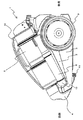
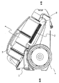
図1は本発明の実施の形態に係る電気掃除機全体の斜視図、図2は本発明の実施の形態に係る電気掃除機本体を右方向から見た側面図、図3は本発明の実施の形態に係る電気掃除機本体を左方向から見た側面図、図4は本発明の実施の形態に係る電気掃除機本体をハンドル中心近傍前後方向でカットし右方向から見た断面図、図5は本発明の実施の形態に係る電気掃除機本体を上方向から見た上面図である。
なお、それぞれの図において、同じ部分または相当する部分には同じ符号を付し、一部の説明を省略する。
以下、図1〜図5により本発明の実施の形態の電気掃除機の構成について説明する。1 is a perspective view of the entire vacuum cleaner according to the embodiment of the present invention, FIG. 2 is a side view of the main body of the vacuum cleaner according to the embodiment of the present invention as viewed from the right side, and FIG. 3 is an embodiment of the present invention. The side view which looked at the vacuum cleaner main body which concerns on the form from the left direction, FIG. 4 is sectional drawing which cut the vacuum cleaner main body which concerns on embodiment of this invention in the front-back direction near handle | steering-wheel center, and was seen from the right direction, FIG. 5 is a top view of the main body of the vacuum cleaner according to the embodiment of the present invention as viewed from above.
In the respective drawings, the same or corresponding parts are denoted by the same reference numerals, and a part of the description is omitted.
Hereinafter, the structure of the vacuum cleaner according to the embodiment of the present invention will be described with reference to FIGS.
図1に示すように、100は本発明の実施の形態の電気掃除機であり、本体1とホース体6と集塵器8を備えている。本体1は図1〜図3に示すように、樹脂成形で形成された本体1の上部を構成する上ケース2と本体1の下部を構成する下ケース3とホース体接続部4及び吸気管5と排気管18とにより構成されている。
As shown in FIG. 1,
ホース体6は図1に示すように塵埃を吸引するための吸込具6fと、伸縮構造を有する硬質延長管部6eと、電気掃除機100を操作するための入力を行う操作部6dを備え電気掃除機100の取り回しおよび吸込具6fを操る把持部6cと、例えば蛇腹のような可撓性を有する軟質管部6bと、挿入部6aとにより構成されている。
As shown in FIG. 1, the hose body 6 includes a
本体1において、ホース体接続部4にはホース体接続口7が設けられており、図1に示すようにホース体6の一端部に設けられた挿入部6aを着脱自在に接続できるようになっている。
In the main body 1, a hose
図2、図3に示すように本体1の上部を構成する上ケース2は、前側から後側に向かって上方に傾斜しており、その傾斜に沿って図5に示すように本体1の側面の一方に吸気管5、他方に排気管18を有している。
2 and 3, the
吸気管5は一端をホース体接続部4と流入口13で接続され、ホース体接続部4と吸気管5の空気経路とが連通するようになっている。また、上ケース2には、集塵器8に設けられた空気排出部16と空気経路とを連通するための連通口17(図7(a)、図8参照)を備えるフィルターカバー11が取付けられている。なお、フィルターカバー11の取付け構造等については後段で詳述する。
One end of the
本体1内には図4に示すように、電動送風機21が、電動送風機収納室20に収納され、配設されている。電動送風機21は、塵埃を吸引するための吸引風を発生させる。電動送風機21の空気経路上流にはフィルターカバー11に覆われ保持されているフィルターユニット23が配設されている。フィルターユニット23は、電動送風機21の保護を目的として電動送風機21に異物が侵入しないように設けられている。
As shown in FIG. 4, the
電動送風機21は空気を吸引するためにモーター(図示せず)により高速で羽根(図示せず)を回転させている。このため、電動送風機21は、もしも異物を吸込んでしまうと羽根(図示せず)に絡まる等して回転が落ち性能が低下したり、硬い異物では羽根(図示せず)が変形や損傷するなどして性能が低下したり、又は完全に回転が停止して故障したりする可能性がある。このような事態を避けるため、電動送風機21は、フィルターユニット23によって保護されている。
The
さらに、本体1内には操作部6dからの入力により電動送風機21の駆動等を制御するための制御基板22等が配設されている。
Further, a
集塵器8は、吸引された空気に含まれる塵埃を捕集するためのものである。塵埃を捕集する方式としては、塵埃を含んだ空気から遠心力により塵埃と空気とを分離するサイクロン式や、塵埃を含んだ空気を通気性のある紙袋体に通過させ塵埃を捕集する紙パック式等があるが、本発明の実施の形態は塵埃の捕集方式に限定されるものではなく、捕集方式は適宜選択可能である。
The
集塵器8は、上ケース2の吸気管5と排気管18とに挟まれた箇所に、吸気管5と排気管18と同様に傾斜に沿って着脱自在に取り付けられている。集塵器8にはレバー(図示せず)と本体係止手段(図示せず)が設けられていて、レバーを操作すると本体1との係止状態が解除され本体1から分離可能となる。
The
それから集塵器8は、図1、図5に示すように吸気管5側に突出した吸引口15を有しており、吸気管5の他端側に設けられた流出口14と着脱自在に接続され吸気管5と集塵器8の空気経路が連通するようになっている。
Then, the
また、集塵器8は、前述したように空気排出部16を有しており、上ケース2に取付けられたフィルターカバー11に設けられた連通口17と接続され、集塵器8と本体1の空気経路が連通するようになっていて、その空気経路の下流には前述のフィルターユニット23、電動送風機収納室20及び電動送風機21が備えられている。
Moreover, the
さらに集塵器8にはハンドル12が設けられている。このハンドル12は集塵器8が本体1から分離されている場合の移動に使用されるが、集塵器8の本体1への取付け面側と反対側に設けられていて、集塵器8が本体1に取付けられている場合には本体1移動用のハンドルとしても使用される兼用ハンドルとなっている。
Further, the
ここで空気の流れを説明すると、電動送風機21を駆動させることで吸引風が発生し塵埃を含んだ空気が図1に示す吸込具6fから吸引される。吸引された塵埃を含んだ空気はホース体6を通り、ホース体接続部4から流入口13で連結された吸気管5を経由し吸気管5の流出口14から集塵器8の吸引口15へ流れる。
Here, the flow of air will be described. When the
集塵器8において塵埃が捕集され取り除かれた空気は、空気排出部16を通りフィルターカバー11に設けられた連通口17から本体1に送られ、フィルターユニット23を通過し電動送風機21を経由して制御基板22等を冷却した後、本体1内の空気経路(図示せず)を通過して排気管18(図3参照)へ送られ、排気管18に設けられた排気口19(図3参照)から本体1外へ排出されるようになっている。
The air collected and removed by the
次に図6〜図10により本発明の実施の形態の電気掃除機のフィルターカバー11と本体1(上ケース2)との連結構造や係止構造、及び係止手段の動作について説明する。
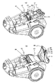
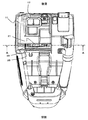
図6は本発明の実施の形態に係る電気掃除機本体1を後方向から見た後面図、図7(a)は本発明の実施の形態に係る電気掃除機の集塵器8を外した状態の斜視図、図7(b)は本発明の実施の形態に係る電気掃除機の集塵器8を外し、フィルターカバー11を開けた状態の斜視図、図8は本発明の実施の形態に係る電気掃除機の集塵器8を外した状態の上面図、図9(a)は図8に示す上面図をA−A断面でカットし前方向から見たA−A断面図、図9(b)は係止手段25が係止されていない状態のA−A断面図、図10は図4に示す断面図のフィルターカバー11周辺の要部拡大図、図11(a)〜(d)は係止手段25周辺断面の要部を拡大した係止手段の動作図である。
なお、それぞれの図において、同じ部分または相当する部分には同じ符号を付し、一部の説明を省略する。Next, referring to FIGS. 6 to 10, the connection structure and the locking structure of the
FIG. 6 is a rear view of the vacuum cleaner main body 1 according to the embodiment of the present invention as viewed from the rear, and FIG. 7A is a view of the
In the respective drawings, the same or corresponding parts are denoted by the same reference numerals, and a part of the description is omitted.
フィルターカバー11は図6に示すように、本体1の後側において、樹脂成形で形成された連結部材24によって、本体1の上部を構成する上ケース2と連結されている。連結状態を詳しく説明すると、図10に示すように連結部材24は、上ケース2に設けられた連結部材保持部34に樹脂成形品の弾性で圧入するようにして爪掛け部35で保持されている。
As shown in FIG. 6, the
フィルターカバー11は、連結部材24に設けられた回動軸受け部36に、フィルターカバー11に一体的に設けられた回動軸32を圧入するようにして回動自在に保持されていて、図7(b)に示すように回動軸32を中心に後方へ向かって約90度の角度で開放するようになっている。
The
連結部材24を使用せず、上ケース2にフィルターカバー11の回動軸32を保持する受け部を一体的に設けることも可能であるが、上ケース2とフィルターカバー11とは外観を構成する部品でもあり、剛性を優先して材料を選択すると外観の美しさが低下してしまう。
Although the connecting
また、外観の美しさを優先すると耐磨耗性の高い材料を選択し難いということもある。従って、上ケース2とフィルターカバー11との外観の美しさ確保と、回動軸の受け部の強度、剛性確保、耐磨耗性確保等とをそれぞれ考慮すると、連結部材24を強度、剛性、耐磨耗性の高い材料で形成した別部品として、上ケース2とフィルターカバー11とを連結することが望ましい。さらに別部品とした連結部材24が目立たないようにフィルターカバー11等の色を変更することも可能である。そうすることで、上ケース2とフィルターカバー11の外観の美しさを確保したまま、強度、剛性、耐磨耗性も確保した耐久性の高い連結構造が実現可能となる。
In addition, when the appearance is prioritized, it may be difficult to select a material with high wear resistance. Therefore, considering the beauty of the outer appearance of the
なお、本発明の実施の形態では図6のように連結部材24が2つ設けられた例を示したが、連結部材24の使用数は2つに限定されるものではなく、設定されたフィルターカバー11の大きさにより1つでも3つでも仕様にあわせて使用数は適宜、選択可能である。
In the embodiment of the present invention, an example in which two connecting
それから、フィルターカバー11には、図7(a)、図8に示すように本体1の上部を構成する上ケース2と連結されている側と反対側の端部に2個一対の係止手段25が設けられている。フィルターカバー11は、係止手段25のそれぞれが、図7(b)に示す上ケース2に設けられた係止部26と係合することで、上ケース2に係止されている。
Then, as shown in FIGS. 7A and 8, the
図9(a)により係止構造を詳しく説明すると、係止手段25は係止解除ボタン28と係止軸部30とを一体的に備えており、係止手段25の係止軸部30は、フィルターカバー11に一体的に設けられた係止軸受け部29に摺動自在に挿入されている。
The locking structure will be described in detail with reference to FIG. 9A. The locking means 25 is integrally provided with a locking
係止解除ボタン28の裏側と固定部材37との間には略V字上に曲げられた板バネ27が設けられていて、この板バネ27の付勢力により係止手段25に係止方向Xの力が働く。係止軸部30は、係止軸受け部29から3乃至5mm程度長くなっているので、板バネ27の付勢力により係止軸部30の先端部が係止軸受け部29の端部から3乃至5mm程度突出するようになっている。
A
同様に係止解除ボタン28も板バネ27の付勢力によりフィルターカバー11に設けられた開口から突出するようになっている。係止解除ボタン28の開口からの突出寸法は係止軸部30の先端部が係止軸受け部29の端部から突出する最大寸法以上、例えば5mm突出している場合は5mm以上となるように設定しており、これを係止解除ボタン28の動作寸法としている。
Similarly, the
前述の板バネ27の付勢力により係止軸受け部29の端部から3乃至5mm程度突出した係止軸部30の先端部が、上ケース2に設けられた係止部26に入り込むことで、フィルターカバー11と上ケース2の間にフィルターユニット23を収めるようにしてフィルターカバー11と上ケース2が係止された状態となり固定される(図4参照)。
The leading end portion of the locking
その後、掃除機100を使用するときには集塵器8を必ず取付けることになるが、もしフィルターカバー11と上ケース2を係止することを忘れていたとしても集塵器8を取付けることで係止されるようになっている。
After that, when using the
図11(a)〜(d)は係止手段25周辺断面の要部を拡大した係止手段の動作図である。図11(a)に示すように係止軸部30の先端部の、係止部26の方向に向かう下側には、傾斜形状部31が設けられている。係止解除ボタン28を操作しない状態でフィルターカバー11を係止方向Yの方向へ押し込んでいくと、この傾斜形状部31が係止部26が設けられている側壁38の角部39に接触するようになる。
FIGS. 11A to 11D are operation diagrams of the locking means in which the main part of the section around the locking means 25 is enlarged. As shown in FIG. 11A, an
接触した状態から、さらにフィルターカバー11を押し込むと、図11(b)のように板バネ27の付勢力に抗しながら、係止部26が設けられている側壁38の角部39を、傾斜形状部31が滑り、係止手段25は、板バネ27の付勢力に抗しながら係止解除方向へ動く。そして、図11(C)のように係止軸部30の先端部が、側壁38と接触しながら係止方向へ押し込まれていく。
When the
そして係止軸部30が係止部26の設けてられている箇所にくると、図11(d)のように板バネ27の付勢力により係止軸部30が係止部26に入り込むようになり、フィルターカバー11と上ケース2が係止された状態となる。
When the locking
このようにフィルターカバー11を押し込むとフィルターカバー11と上ケース2が係止されるようになるが、図10に示すように集塵器8には押し込みリブ33が設けられている。押し込みリブ33は、集塵器8が取り付いた状態において、フィルターカバー11の係止手段25が設けられている近傍の角部に上方から接する位置に、設けられている。
Thus, when the
よって、フィルターカバー11が係止されていない状態で集塵器8を取付けようとすると、取付けの途中で押し込みリブ33がフィルターカバー11の係止手段25が設けられている近傍の角部と接触することになるので、押し込みリブ33によってフィルターカバー11が係止方向へ押し込まれることになる。
Therefore, if the
そうすると、係止手段25は前述のような構成となっているので、フィルターカバー11が係止されていなくても、使用の際に集塵器8を取り付ければ、集塵器8を取付ける動作の中でフィルターカバー11も係止されるようになり、集塵器8が本体1に取り付けられるのとほぼ同じタイミングで簡単で確実にフィルターカバー11が係止されるようになっている。
Then, since the locking means 25 has the above-described configuration, even if the
なお、ここではフィルターカバー11の係止をしていない(忘れた)場合の集塵器8の取付けによりフィルターカバー11が係止される説明をしたが、前述のような構成となっているので集塵器8を取付ける前にフィルターカバー11を手できちんと係止する際も、フィルターカバー11を押し込むことで簡単に係止させることができる。
Here, the
前述のように係止された状態からフィルターカバー11を開放する時には、板バネ27の付勢力に抗して係止方向Xと反対の方向へ係止解除ボタン28を操作する。但し、係止解除ボタン28は2個一対で独立して動作するように設けられているので片方だけ操作しても片方しか係止状態を解除できない。そのため、両方から、係止解除ボタン28を指等で摘まむように同時に操作をする。
When the
すると、それによりそれぞれの係止軸部30が係止軸受け部29の中を摺動し、係止軸部30の先端部が係止部26から抜ける方向へ移動する。係止軸部30の先端部と係止部26との係止寸法は、係止軸部30の先端部が係止軸受け部29の端部から突出した3乃至5mm程度であるが、前述のように、係止解除ボタン28の動作寸法を、係止軸部30の先端部が係止軸受け部29の端部から突出する最大寸法以上、例えば5mm突出している場合は5mm以上、としているので確実に解除される。
As a result, the respective
解除された状態から係止解除ボタン28を摘まんだまま上に引き上げれば、図7(b)に示すように、フィルターカバー11が回動軸32を中心に後方へ向かって約90度の角度で簡単に開放でき、フィルターユニット23が取り出せるようになる。
If the
ここまでフィルターカバー11の係止と解除とについて説明してきたが、集塵器8が取付けられると、図5のようにフィルターカバー11に設けられた係止手段25の係止解除ボタン28は、集塵器8に覆われるようになる。よって集塵器8が取付けられた状態では、係止解除ボタン28の操作はできない。従って、掃除機100を使用中に誤ってフィルターカバー11が開放されてしまうことがないので、使用者の誤操作を防止でき安全に掃除機100を使用することができる。
Up to this point, the lock and release of the
さらに、前述したようにフィルターカバー11に保持されているフィルターユニット23は電動送風機21の保護を目的として電動送風機21に異物が侵入しないように設けられており、フィルターユニット23を保持するフィルターカバー11が確実に係止されるので電動送風機21の性能低下や故障を防止することができ、電動送風機21の能力を維持することができる。
Further, as described above, the
次に、フィルターカバー11には図12(a)、(b)に示すようにホース体6の保持部50が設けられている。図12(a)は本発明の実施の形態に係る電気掃除機のフィルターカバー11に設けられた保持部50に、硬質延長管部6eの挿入片6gを挿入した状態の側面図、図12(b)は図12(a)の保持部50近傍で切断した側方断面図である。
Next, the
保持部50はフィルターカバー11とは別体の、樹脂成形で形成された部品であり、フィルターカバー11の回動軸32側(本体1の後側)にネジ51で固定されている。保持部50は、図12(a)のように掃除中にホース体6を床に置くことなく保持しておくためのものである。
The holding
保持部50は図12(b)に示すように断面形状がコの字をしており、そこにホース体6の硬質延長管部6eに設けられたL字形状の挿入片6gを挿入するようになっている。挿入するたびに、挿入片6gは保持部50に衝撃を与えることになるが、前述したようにフィルターカバー11は外観を構成する部品でもあり、剛性を優先して材料を選択すると外観の美しさが低下してしまう。そのため、強度、剛性確保、耐磨耗性確保等を考慮し、保持部50は別体となっている。また、使用者が挿入し易くなるようフィルターカバー11や他の部品と保持部50との色を変えることで使用者の目安としている。
As shown in FIG. 12B, the holding
このようにすることで清掃中に少しの間、別の用事を済ませたい状況が発生しても、わざわざホース体6を床に置く必要がないので、腰や膝を曲げてホース体6を拾い上げることなく直ぐに再びホース体6を手に取ることができる。従って、使用者がホース体6を床から拾い上げる煩わしさを解消することができ、使用者の腰や膝に負担を掛けることを少なくすることができる。 In this way, even if there is a situation where it is desired to complete another task for a while during cleaning, it is not necessary to put the hose body 6 on the floor. Therefore, the waist and knees are bent and the hose body 6 is picked up. The hose body 6 can be picked up again immediately without any problems. Therefore, the troublesomeness of the user picking up the hose body 6 from the floor can be eliminated, and the burden on the user's waist and knees can be reduced.
なお、本実施の形態では保持部50をフィルターカバー11の回動軸32側(本体1の後側)に設ける構成で説明しているが、図13(a)のように側面方向に設けてもよく、側面方向にネジ座を設けておけばネジ51を取り外すことでフィルターカバー11の回動軸32側から側面方向に取付け位置を移動、変更することが可能となる。ネジ1本での取り外しで移動、変更可能であるので、使用者がドライバー等の工具を使用することで自分の使い勝手の良い位置へ移動、変更させることも容易である。
In the present embodiment, the holding
また、保持部50は1箇所に限られるものではなく、図13(b)のようにフィルターカバー11の回動軸32側と側面方向の両方のように複数設けてもよく、複数設けることによって使用者の利便性が向上する。
Further, the holding
さらに、本実施の形態では硬質延長管部6eに挿入片6gを設けた例を示したが、挿入片6gは、吸込具6fや把持部6c等に設けても良く、ホース体6の構成に合わせ、硬質延長管部6e、吸込具6fや把持部6cのいずれか、又はそれらの全てに設けても、同様に清掃中に少しの間、別の用事を済ませたい状況が発生した場合に、わざわざホース体6を床に置く必要がなく、直ぐに再びホース体6を手に取ることができ使用者がホース体6を床から拾い上げる煩わしさを解消することができる。
Furthermore, although the example which provided the
以上のように本発明の実施の形態においては、フィルターカバー11に本体1へ係止する係止手段25と係止状態の解除操作をする係止解除ボタン28とを備えたので、フィルターカバー11を弾性変形させることなく本体1に係止させることができる。係止解除ボタン28を操作すると係止手段25が解除されるようにしたので、フィルターカバー11を弾性変形させないので、フィルターカバー11の係止解除が安全で容易となり作業性が向上する。またこれにより、係止と解除とを繰り返すことに対する、フィルターカバー11の耐久性を向上させることができる。
As described above, in the embodiment of the present invention, the
また、フィルターカバー11を連結する部品を、強度、剛性、耐磨耗性の高い材料で形成した別部品としたので、フィルターカバー11を繰り返しの開閉する際の耐久性が向上する。それから、掃除中にはフィルターカバー11が集塵器8に覆われるようになっているので、掃除中に誤ってフィルターカバー11を開放してしまうことがなく使用者の誤操作を防止することができ、安全に掃除機100を使用することができる。
In addition, since the component for connecting the
1 本体、2 上ケース、3 下ケース、4 ホース体接続部、5 吸気管、6 ホース体、6a 挿入部、6b 軟質管部、6c 把持部、6d 操作部、6e 硬質延長管部、6f 吸込具、6g 挿入片、7 ホース体接続口、8 集塵器、9 車輪、10 キャスター、11 フィルターカバー、12 ハンドル、13 流入口、14 流出口、15 吸引口、16 空気排出部、17 連通口、18 排気管、19 排気口、20 電動送風機収納室、21 電動送風機、22 制御基板、23 フィルターユニット、24 連結部材、25 係止手段、26 係止部、27 板バネ、28 係止解除ボタン、29 係止軸受け部、30 係止軸部、31 傾斜形状部、32 回動軸、33 押し込みリブ、34 連結部材保持部、35 爪掛け部、36 回動軸受け部、37 固定部材、38 側壁、39 角部、50 保持部、51 ネジ、100 電気掃除機、X 係止方向、Y 係止方向。 DESCRIPTION OF SYMBOLS 1 Main body, 2 Upper case, 3 Lower case, 4 Hose body connection part, 5 Intake pipe, 6 Hose body, 6a Insertion part, 6b Soft pipe part, 6c Gripping part, 6d Operation part, 6e Hard extension pipe part, 6f Suction Tools, 6g Insertion piece, 7 Hose body connection port, 8 Dust collector, 9 Wheel, 10 Caster, 11 Filter cover, 12 Handle, 13 Inlet, 14 Outlet, 15 Suction port, 16 Air outlet, 17 Communication port , 18 Exhaust pipe, 19 Exhaust port, 20 Electric blower storage chamber, 21 Electric blower, 22 Control board, 23 Filter unit, 24 Connecting member, 25 Locking means, 26 Locking portion, 27 Leaf spring, 28 Lock release button , 29 Locking bearing part, 30 Locking shaft part, 31 Inclined shape part, 32 Rotating shaft, 33 Pushing rib, 34 Connecting member holding part, 35 Claw hook part, 36 Rotating Receiving unit, 37 fixing member, 38 side wall, 39 corners, 50 holding portion, 51 screw, 100 vacuum cleaner, X locking direction, Y locking direction.
Claims (16)
該電動送風機により吸引された空気に含まれる塵埃を捕集する集塵器と、
前記集塵器の下流側に設けられたフィルターと、
該フィルターを開閉自在に覆うフィルターカバーと、を備え、
前記フィルターカバーは、一端側が前記本体に回動自在に軸支され、他端側が前記本体に設けられた係止部と係脱可能に係止され、当該係止部から係止状態の解除操作をする係止解除ボタンを備えたことを特徴とする電気掃除機。An electric blower disposed in the body,
A dust collector for collecting dust contained in the air sucked by the electric blower;
A filter provided downstream of the dust collector;
A filter cover that covers the filter in an openable and closable manner;
One end side of the filter cover is pivotally supported by the main body, and the other end side is detachably locked with a locking portion provided on the main body, and the locking operation is released from the locking portion. A vacuum cleaner comprising an unlocking button for performing the operation.
前記フィルターカバーには回動軸が設けられ、当該回動軸は前記連結部材に回動自在に軸支されていることを特徴とする請求項1乃至請求項4何れか1項に記載の電気掃除機。The body includes a connecting member;
5. The electric according to claim 1, wherein the filter cover is provided with a rotation shaft, and the rotation shaft is rotatably supported by the connecting member. Vacuum cleaner.
該電動送風機により吸引された空気に含まれる塵埃を捕集する集塵器と、
前記集塵器の下流側に設けられたフィルターと、
該フィルターを開閉自在に覆うフィルターカバーと、を備え、
前記フィルターカバーは、前記本体後側で前記本体に回動自在に軸支され、前記本体前側で前記本体に設けられた係止部へ係脱可能に係止する係止手段と、係止状態の解除操作をする係止解除ボタンとを備え、
前記係止解除ボタンは前記集塵器が前記本体に取付けられた状態の時には前記集塵器に覆われて操作ができないようになっていて、
前記フィルターカバーが係止されていない状態で、前記集塵器を前記本体の取付け方向に接近させた場合、前記集塵器が前記フィルターカバーと接触し、前記係止手段がその係止位置まで押し込まれることで、前記フィルターカバーが前記本体に係止されることを特徴とする電気掃除機。An electric blower disposed in the body,
A dust collector for collecting dust contained in the air sucked by the electric blower;
A filter provided downstream of the dust collector;
A filter cover that covers the filter in an openable and closable manner;
The filter cover is pivotally supported by the main body on the rear side of the main body and is pivotally supported on the front side of the main body. The filter cover is detachably locked to a locking portion provided on the main body on the front side of the main body. And a release button for releasing the
The lock release button is covered with the dust collector when the dust collector is attached to the main body and cannot be operated,
When the dust collector is brought close to the mounting direction of the main body in a state where the filter cover is not locked, the dust collector comes into contact with the filter cover, and the locking means reaches the locked position. The vacuum cleaner, wherein the filter cover is locked to the main body by being pushed in.
前記フィルターカバーに、前記ホース体の保持部を設けたことを特徴とする請求項1又は請求項9何れか1項に記載の電気掃除機。A hose body provided with at least a suction tool, a hard tube portion, and a gripping portion for handling,
The vacuum cleaner according to claim 1, wherein the filter cover is provided with a holding portion for the hose body.
該電動送風機により吸引された空気に含まれる塵埃を捕集する集塵器と、
前記集塵器の下流側に設けられたフィルターと、
該フィルターを開閉自在に覆うフィルターカバーと、
少なくとも吸込具と硬質管部と取り回しの為の把持部とが設けられたホース体と、を備え、
前記フィルターカバーに、前記ホース体の保持部を設けたことを特徴とする電気掃除機。An electric blower disposed in the body,
A dust collector for collecting dust contained in the air sucked by the electric blower;
A filter provided downstream of the dust collector;
A filter cover covering the filter so as to be freely opened and closed;
A hose body provided with at least a suction tool, a hard tube portion, and a gripping portion for handling,
An electric vacuum cleaner, wherein the filter cover is provided with a holding portion for the hose body.
Priority Applications (1)
| Application Number | Priority Date | Filing Date | Title |
|---|---|---|---|
| JP2013517919A JP5578281B2 (en) | 2011-06-02 | 2012-04-10 | Electric vacuum cleaner |
Applications Claiming Priority (4)
| Application Number | Priority Date | Filing Date | Title |
|---|---|---|---|
| JP2011124102 | 2011-06-02 | ||
| JP2011124102 | 2011-06-02 | ||
| JP2013517919A JP5578281B2 (en) | 2011-06-02 | 2012-04-10 | Electric vacuum cleaner |
| PCT/JP2012/059760 WO2012165054A1 (en) | 2011-06-02 | 2012-04-10 | Electric vacuum cleaner |
Publications (2)
| Publication Number | Publication Date |
|---|---|
| JP5578281B2 true JP5578281B2 (en) | 2014-08-27 |
| JPWO2012165054A1 JPWO2012165054A1 (en) | 2015-02-23 |
Family
ID=47258919
Family Applications (1)
| Application Number | Title | Priority Date | Filing Date |
|---|---|---|---|
| JP2013517919A Expired - Fee Related JP5578281B2 (en) | 2011-06-02 | 2012-04-10 | Electric vacuum cleaner |
Country Status (3)
| Country | Link |
|---|---|
| JP (1) | JP5578281B2 (en) |
| TW (2) | TWI609667B (en) |
| WO (1) | WO2012165054A1 (en) |
Families Citing this family (3)
| Publication number | Priority date | Publication date | Assignee | Title |
|---|---|---|---|---|
| KR102560970B1 (en) * | 2016-03-31 | 2023-07-31 | 엘지전자 주식회사 | Cleaner |
| KR101852435B1 (en) * | 2016-05-03 | 2018-04-26 | 엘지전자 주식회사 | Vacuum cleaner |
| TWI696440B (en) * | 2018-01-29 | 2020-06-21 | 王勝豊 | Cleaning device |
Citations (9)
| Publication number | Priority date | Publication date | Assignee | Title |
|---|---|---|---|---|
| JP2001231729A (en) * | 2000-02-24 | 2001-08-28 | Matsushita Electric Ind Co Ltd | Vacuum cleaner |
| JP2004008295A (en) * | 2002-06-04 | 2004-01-15 | Matsushita Electric Ind Co Ltd | Vacuum cleaner |
| JP2004290337A (en) * | 2003-03-26 | 2004-10-21 | Matsushita Electric Ind Co Ltd | Vacuum cleaner |
| JP2009101130A (en) * | 2007-10-19 | 2009-05-14 | Samsung Kwangju Electronics Co Ltd | Suction nozzle hanging apparatus for use in vacuum cleaner |
| JP2010057967A (en) * | 2009-12-15 | 2010-03-18 | Mitsubishi Electric Corp | Vacuum cleaner |
| JP2011019624A (en) * | 2009-07-14 | 2011-02-03 | Toshiba Corp | Extension pipe for cleaner, and vacuum cleaner |
| JP2011098150A (en) * | 2009-11-09 | 2011-05-19 | Mitsubishi Electric Corp | Vacuum cleaner |
| JP2011098105A (en) * | 2009-11-06 | 2011-05-19 | Mitsubishi Electric Corp | Vacuum cleaner |
| JP2011098082A (en) * | 2009-11-06 | 2011-05-19 | Mitsubishi Electric Corp | Vacuum cleaner |
Family Cites Families (1)
| Publication number | Priority date | Publication date | Assignee | Title |
|---|---|---|---|---|
| CN102018479B (en) * | 2010-10-19 | 2013-01-23 | 宁波富佳实业有限公司 | Multifunctional vertical dust collector |
-
2012
- 2012-04-10 JP JP2013517919A patent/JP5578281B2/en not_active Expired - Fee Related
- 2012-04-10 WO PCT/JP2012/059760 patent/WO2012165054A1/en active Application Filing
- 2012-05-22 TW TW104105996A patent/TWI609667B/en not_active IP Right Cessation
- 2012-05-22 TW TW101118106A patent/TWI484934B/en not_active IP Right Cessation
Patent Citations (9)
| Publication number | Priority date | Publication date | Assignee | Title |
|---|---|---|---|---|
| JP2001231729A (en) * | 2000-02-24 | 2001-08-28 | Matsushita Electric Ind Co Ltd | Vacuum cleaner |
| JP2004008295A (en) * | 2002-06-04 | 2004-01-15 | Matsushita Electric Ind Co Ltd | Vacuum cleaner |
| JP2004290337A (en) * | 2003-03-26 | 2004-10-21 | Matsushita Electric Ind Co Ltd | Vacuum cleaner |
| JP2009101130A (en) * | 2007-10-19 | 2009-05-14 | Samsung Kwangju Electronics Co Ltd | Suction nozzle hanging apparatus for use in vacuum cleaner |
| JP2011019624A (en) * | 2009-07-14 | 2011-02-03 | Toshiba Corp | Extension pipe for cleaner, and vacuum cleaner |
| JP2011098105A (en) * | 2009-11-06 | 2011-05-19 | Mitsubishi Electric Corp | Vacuum cleaner |
| JP2011098082A (en) * | 2009-11-06 | 2011-05-19 | Mitsubishi Electric Corp | Vacuum cleaner |
| JP2011098150A (en) * | 2009-11-09 | 2011-05-19 | Mitsubishi Electric Corp | Vacuum cleaner |
| JP2010057967A (en) * | 2009-12-15 | 2010-03-18 | Mitsubishi Electric Corp | Vacuum cleaner |
Also Published As
| Publication number | Publication date |
|---|---|
| TWI484934B (en) | 2015-05-21 |
| TWI609667B (en) | 2018-01-01 |
| TW201311202A (en) | 2013-03-16 |
| TW201519846A (en) | 2015-06-01 |
| WO2012165054A1 (en) | 2012-12-06 |
| JPWO2012165054A1 (en) | 2015-02-23 |
Similar Documents
| Publication | Publication Date | Title |
|---|---|---|
| EP2988641B1 (en) | Vacuum cleaner including a removable dirt collection assembly | |
| EP1795105B1 (en) | Vacuum cleaner | |
| JP6228856B2 (en) | Electric vacuum cleaner | |
| EP3209176B1 (en) | Vacuum cleaner having a conversion valve | |
| EP2529652B1 (en) | A cleaning appliance | |
| JP2017164026A (en) | Handy vacuum cleaner | |
| JP5429370B2 (en) | Electric vacuum cleaner | |
| JP5677796B2 (en) | Electric vacuum cleaner | |
| US20160095485A1 (en) | Vacuum cleaner including a removable dirt collection assembly | |
| JP5578281B2 (en) | Electric vacuum cleaner | |
| CA2843333C (en) | Vacuum cleaner with accessory tool assembly | |
| CN109310254B (en) | Surface cleaning device | |
| JP6572352B2 (en) | Suction port body and electric vacuum cleaner provided with the same | |
| JP2016195917A (en) | Suction port body and vacuum cleaner including the same | |
| JP7461729B2 (en) | Vacuum cleaner | |
| JP6572366B2 (en) | Suction port body and electric vacuum cleaner provided with the same | |
| JP6572367B2 (en) | Suction port body and electric vacuum cleaner provided with the same | |
| US20210290021A1 (en) | Surface cleaning apparatus with removable air treatment assembly | |
| JP2014023859A (en) | Electric vacuum cleaner | |
| JP6921291B2 (en) | Vacuum cleaner | |
| US11445878B2 (en) | Surface cleaning apparatus with removable air treatment member assembly | |
| US11766156B2 (en) | Surface cleaning apparatus with removable air treatment member assembly | |
| US11666193B2 (en) | Surface cleaning apparatus with removable air treatment member assembly | |
| JP5155201B2 (en) | Electric vacuum cleaner | |
| JP2019187581A (en) | Vacuum cleaner |
Legal Events
| Date | Code | Title | Description |
|---|---|---|---|
| TRDD | Decision of grant or rejection written | ||
| A01 | Written decision to grant a patent or to grant a registration (utility model) |
Free format text: JAPANESE INTERMEDIATE CODE: A01 Effective date: 20140610 |
|
| A61 | First payment of annual fees (during grant procedure) |
Free format text: JAPANESE INTERMEDIATE CODE: A61 Effective date: 20140623 |
|
| R150 | Certificate of patent or registration of utility model |
Ref document number: 5578281 Country of ref document: JP Free format text: JAPANESE INTERMEDIATE CODE: R150 |
|
| R250 | Receipt of annual fees |
Free format text: JAPANESE INTERMEDIATE CODE: R250 |
|
| R250 | Receipt of annual fees |
Free format text: JAPANESE INTERMEDIATE CODE: R250 |
|
| R250 | Receipt of annual fees |
Free format text: JAPANESE INTERMEDIATE CODE: R250 |
|
| R250 | Receipt of annual fees |
Free format text: JAPANESE INTERMEDIATE CODE: R250 |
|
| R250 | Receipt of annual fees |
Free format text: JAPANESE INTERMEDIATE CODE: R250 |
|
| R250 | Receipt of annual fees |
Free format text: JAPANESE INTERMEDIATE CODE: R250 |
|
| LAPS | Cancellation because of no payment of annual fees |