EP1269823A1 - System zur Verstellung eines Erntevorsatzes einer Erntemaschine - Google Patents
System zur Verstellung eines Erntevorsatzes einer Erntemaschine Download PDFInfo
- Publication number
- EP1269823A1 EP1269823A1 EP02013853A EP02013853A EP1269823A1 EP 1269823 A1 EP1269823 A1 EP 1269823A1 EP 02013853 A EP02013853 A EP 02013853A EP 02013853 A EP02013853 A EP 02013853A EP 1269823 A1 EP1269823 A1 EP 1269823A1
- Authority
- EP
- European Patent Office
- Prior art keywords
- header
- crop
- transmitter
- receiver
- ground
- Prior art date
- Legal status (The legal status is an assumption and is not a legal conclusion. Google has not performed a legal analysis and makes no representation as to the accuracy of the status listed.)
- Granted
Links
Images


Classifications
-
- A—HUMAN NECESSITIES
- A01—AGRICULTURE; FORESTRY; ANIMAL HUSBANDRY; HUNTING; TRAPPING; FISHING
- A01D—HARVESTING; MOWING
- A01D41/00—Combines, i.e. harvesters or mowers combined with threshing devices
- A01D41/12—Details of combines
- A01D41/14—Mowing tables
- A01D41/141—Automatic header control
Definitions
- the invention relates to a system for adjusting a header a harvesting machine, with one for adjusting the Harvester head set up opposite the harvester Adjustment device, one for controlling the adjustment device set up control and a transmitter and receiver, which emits signals onto a surface in the direction of travel before the header on one of the harvesters the distance to be covered is on the crop, and receives signals reflected from the surface and the controller a control signal for adjustment based on the received signals of the header feeds, the controller, the adjusting device controlled based on the control signal such that the Header substantially opposite constant position occupies the ground.
- a self-propelled harvester such as a Combine harvester
- a header is usually equipped with a header, around in some transversely spaced rows or a considerable To intervene with wide standing crops.
- an automatic height control system for the header provided that is typically a mechanical Sensor or an acoustic sensor or similar, contactless Includes floor sensing devices that are attached to the header. Examples of known devices are described in US Pat. No. 6,173,614 A, US 5,704,200 A, US 5,463,854 A, US 5,155,984 A and US 4,171,606 A is shown.
- US 4,776,153 shows a height control system for a header with a variety of sensors and one Tilt control.
- the tilt response time is at high speeds or in fields with very irregular surface contours often used for headers automatic tilt systems, such as those mentioned above US 4,776,153 A are shown too long to fit the header in To keep essentially parallel to the ground.
- EP 0 887 660 A proposes a laser scanning device to determine the distance of a grain ear surface from a harvester. Your signal will used to control the height of the cutting unit or reel. In the way in which the signal is used is not clear disclosed.
- the object underlying the invention is seen in an improved control system for the position of a header a combine harvester or other harvesters provide.
- the invention proposes that the transmitter and receiver have a area well in front of the header applied to a signal and based on the reflected signal - In particular its transit time and / or amplitude - one Information about the height of the area to be used wins. This will cause the header (and on height sensors attached to it) on the examined area gained predictive information about which Position the header towards the harvester too is adjusted when it arrives at the examined area. The acted upon with the control signal of the transmitter and receiver Control controls the adjustment device in good time, see above that the header does not change until the investigated area reached in the reflected from the Signal derived position is.
- the transmitter and receiver only with one point or a limited number of Points of the path lying in front of the harvesting machine cooperates. There is only one, more solid and therefore relatively inexpensive Sensor required. Since the distance signal is only one Part of the soil in front of the harvester is represented Incorrect measurements and incorrect settings of the header are conceivable, if the ground contour is wavy across the direction of travel. It lends itself therefore to use a transmitter and receiver, the to capture a ground contour in a cross to Direction of travel is set up. Based the recorded ground contour is controlled by the control Adjustment device controlled so that the header takes the desired position.
- the work area of the sender and receiver usually corresponds at least the working width of the header.
- the transmitter and receiver could be attached to the header be so that it directly provides information about the position of the header against the ground. Because the However, the header often vibrates relatively strongly, the Transmitter and receiver preferably separated from the header and independent of changes in the position of the header appropriate. It is particularly mounted on the harvester, for example at your operator's cabin.
- the adjusting device can comprise a lifting system which is used for Raising and lowering the header against the Harvester is set up.
- a lifting system which is used for Raising and lowering the header against the Harvester is set up.
- an inclination system is provided which Swiveling the header around a horizontal, along the axis of travel of the harvester is set up.
- the controller controls the height and / or Inclination of the header towards the harvester, so that the desired position of the header opposite the Soil is maintained.
- the transmitter and receiver can be set up to distance between him and the surface where the signal can be seen is reflected. Once it becomes apparent that the distance is on a certain point decreases or increases, the Adjustment device causes the header on the raise or lower the corresponding point.
- the signals used by the transmitter and receiver can be electromagnetic Signals of a frequency range are used that the Penetrate crop, e.g. B. radar beams, and from the ground be reflected. Then the controller is able to Recognize the contour of the ground directly.
- the The transmitter and receiver emit and receive signals from the Crop are reflected, for example light waves, especially in the infrared range.
- the bottom contour can then be derived from the contour of the crop, z. B. the Height of a detected crop edge can be taken into account can.
- the header can in this embodiment in one predetermined height below the top of the crop operated to increase throughput through the harvester diminish and increase their productivity.
- the control can be used for predictive contour determination also the ground contour at the points on the ground take into account that of the wheels or crawlers of the Be driven over the harvester. This can cause bumps or surveys are taken into account.
- one per se known laser distance measuring device are used for Scanning a certain angular range in front of the harvester is set up. Because the scan angle range in many such transmitters and receivers smaller than that for scanning serving the entire working width of the header Angular range, it lends itself to the transmitter and receiver a rotatable structure, e.g. B. a turntable, which is a scanning of the entire width of the header allows.
- a rotatable structure e.g. B. a turntable, which is a scanning of the entire width of the header allows.
- Such laser distance measuring devices scanning an angular range can also be used to detect a Serve crop edge. You generate a crop edge position signal, for automatic steering of the harvesting machine can be used. Is the laser distance measuring device mounted on a rotatable structure, can the latter then the laser distance measuring device over the Rotate the width of the header if none at all Crop edge signal is provided for steering control.
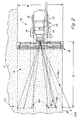
- an agricultural Harvester shown in the form of a combine 10 which is a main frame 12 with a wheel assembly 13 has, the front and rear, in engagement with the floor located wheels 14 and 15, which the main frame 12th to move forward across a field of crop to be harvested Carry crop.
- wheels 14 and 15 are shown, the wheel arrangement 13 caterpillars in ground contact include or consist of.
- the drive for the front Wheels 14 is via a conventional hydrostatic transmission provided by a motor attached to the main frame 12.
- a vertically adjustable header 16 in the form of a Harvester is used to harvest crops and one Feed feeder 18.
- the feeder 18 is pivotally connected to the main frame 12 and includes one Conveying device for the harvested crop of a guide drum 20 supply.
- the guide drum 20 carries the material upwards an inlet transition section 22 and one rotatable crop processing device set up for threshing and separating 24 to.
- the rotating crop processing device 24 threshes and separates the harvested good.
- the grain and chaff fall through grates Bottom of the crop processing device 24 in a cleaning system 26.
- the cleaning system 26 removes the chaff and does that clean grain an elevator (not shown) for clean grain to.
- the elevator for clean grain puts the grain in one Grain tank 28 from.
- the clean grain in the grain tank 28 can by an unloading screw conveyor 30 a truck or trailer are fed.
- Threshed-out, grain-free straw is removed from the Good processing device 24 through an outlet 32 Ejection drum 34 fed.
- the ejection drum 34 pushes it Straw in turn from the rear of the combine 10. It is note that the ejection drum 34 freed the grain It could also be fed directly to a straw chopper.
- the Combine 10 is operated from an operator's cab 35 controlled from.
- the crop processing device 24 comprises a cylindrical one Rotor housing 36 and one arranged in rotor housing 36, rotatable rotor 37.
- the front part of the rotor 37 and the Rotor housings 36 define a loading section 38.
- Downstream of the feed section 38 are a threshing section 39, a separating section 40 and an outlet section 41
- Rotor 37 is in the loading section 38 with a conical Rotor drum provided, the helical loading elements for engaging in good that it from the guide drum 20th and receives from the inlet transition area 22.
- the threshing section 39 Immediately downstream of the loading section 38 is the threshing section 39.
- the rotor 37 has a cylindrical one Rotor drum with a number of threshing elements is provided to the goods received from the loading section 38 to thresh.
- the Separation section 40 Downstream of the threshing section 39 is the Separation section 40, in which the threshed good still contained grain is released and by a bottom Rust in the rotor housing 36 into the cleaning system 28 falls.
- the separating section 40 goes into the outlet section 41 above, in which the grain (straw) from the Good processing device 24 is ejected.
- the Harvester shown as a combine harvester 10 for grain harvest it should be noted that the present invention also applies to other types of harvesters can be used have vertically controlled attachments.
- the height of the header 16 is determined by a hydraulic Controlled lifting system, which is marked with a total of 60, and a tilt system for header 16, the total labeled 61 may also be provided to the header 16 substantially parallel to the ground surface to keep.
- Sensor 62 or other conventional height sensing devices, such as acoustic, on in the transverse direction spaced locations of the header attached Sensors provide information about the height of the header 16 ready.
- a converter 64 on the inclined conveyor 18th provides information about the angle of the feeder 18 opposite the main frame 12.
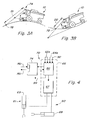
- the signals from the Devices 62 and 64 are connected via lines 62a and 64a ( Figure 4) transferred to a controller 66, the one comprises electrohydraulic valve device 67 around which hydraulic flow to and from one or two lift cylinders 68 to control the between the feeder 18 and the Main frame 12 is or are connected to the lifting system 60 operate to the header 16 within a to maintain the desired operating height range.
- the Valve device 67 also controls expansion and contraction an inclination cylinder 69 to the header 16 by a to rotate from front to back extending axis so that it works parallel to the ground surface.
- the tilt system 61 becomes the cylinder 69 operate to the header 16 for appropriate height correction to tilt around the axis. If sensors on both sides of the Provide a raise or lower indicator, the Cylinder 68 extended or retracted accordingly to the to achieve necessary height correction and the header 16 in maintain a predetermined operating altitude range. On such a height control system is in the aforementioned US 4th 776 153 A.
- the response times of the lifting system 60 and tilt system 61 are often too slow to abrupt changes in the contour of the floor surface compensate, especially if the harvester 10 with is operated at relatively high speeds.
- the Response time can also be too slow, sudden changes the position of the header 16 relative to the ground to compensate for the fact that one or a plurality of wheels 14 and 15 of the wheel arrangement 13 with one Work together the recess or raised surface in the floor contour.
- the ability to harvest the crop in a predetermined Cut distance from ears of corn to increase throughput limit is also limited.
- Improved height control of the header 16 includes a system marked with a total of 70, which or crop contour is anticipated.
- System 70 is attached to the combine 10 to substantially over the total width of the path P of the header 16 soil contour information provide.
- System 70 includes one Transmitter and receiver (transceiver) 74, which is connected to a central Position on the operator's cab 35 is arranged to receive signals 76 to broadcast and receive.
- the transmitter and receiver 74 emits signals down 76t at an acute angle from the plane of the forward direction of the combine 10 in Direction on a floor surface 77 in front of the combine 10.
- the Signals 76t are preferably over the entire width W des Path P of the header 16 scanned or radiated and meet at a distance of the order of 10 to 20 m in front of the operator's cab 35 on the floor.
- Reflected signals 76r are received by the transmitter and receiver 74.
- the Time interval between the emission of a signal 76t and the Receiving signal 76r provides information about the Distance between the transmitter and receiver 74 and the reflective portion 78 of the floor surface or Harvest surface ready. The information about the Distances in turn provide ground contour information ready.
- System 70 will preferably used the operation of the altitude-sensing To complete device 62 on the header 16 and a early response of the height control to yourself quickly to cause changing ground contours to increase the response time reduce and reduce the lifting capacity requirements.
- system 70 can also act as a primary height control of header 16 can be used if desired. If for example the position of the header 16 such is controlled that the crop cut in a certain The distance from the ears is in contact with the ground no problem and the control is primarily with System 70.
- System 70 can also be used to operate the Tilt system 61 to complete and required changes in angle of header 16 to anticipate situations avoid where the header 16 substantially opposite is parallel to the ground. If the one side of the floor for an area in relation to the opposite side rises, can be a foresighted Information for the slope required for this area be provided to provide a timely response from the Inclination system 61 even at high speeds achieve.
- the area scanned by the signals 76 comprises areas 80, essentially in the path of the combine wheel assembly 13 10 lie so that the contour of the wheels 14 and 15th supporting soil can be considered if that System 70 the desired height control response for the area 77 pre-calculated.
- System 70 includes a processor 86 to calculate distances D based on the signal propagation time and to convert the distances into ground contour information.
- the contour information for each surface 77 is shown in stored in a memory to a ground contour history in To provide substantially over a length of path P that differ from the current area 77, from the incoming Signals 76t are received, back to one Distance that is at least equal to the distance between the header 16 and the rear wheels 15.
- Processor 86 can provide the expected height response for a given area 77 based on a time-based history the contour surfaces or a distance-based history to calculate. For a distance-based history, over line 90 provides processor 86 with combine speed information fed. To identify those of the The processor 86 can also have an area traversed by wheels 14, 15 Steering information supplied by an automatic Steering system and / or the manual steering device removed and the future path of the combine 10 is recognizable.
- transmitter and receiver 74 radiate a signal 76t, penetrate the standing crop and the Can reach the ground like a high frequency radar beam.
- a laser range finder such as a laser measurement system of a model of the Series LMS 200 from Sick, or one on one as rotatable Structure-serving turntable 100 attached crop edge sensor ( Figure 5) can be used to create a good surface contour determine which is essentially the underlying Approximate floor surface contour.
- the crop edge sensor of Figure 5 has a limited scanning range of approximately 15 ° around which Determine the edge of the crop and enter it on line 99 Provide guidance control signal.
- the turntable 100 rotates the sensor around an upright axis, in several Steps while lying between guidance control signals Periods of time performing a scan of the to allow the entire width of the header 16, which in is of the order of 90 °.
- the frequency of the samples is preferably dependent on deviations in the crop edge from a straight path, with more scans possible when the crop edge is straight and less Leadership corrections are required.
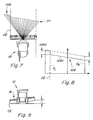
- FIG. 6, in which a typical scanning signal of the laser good edge sensor 74 from FIG. 5 is reproduced across the entire width of the header 16 by the solid line at 106.
- the distance calculated from the time taken by signals 76t to travel to area 77 and the corresponding reflected signals 76r to be received by transmitter and receiver 74 is for a typical scan of about 90 ° against that Scanning angle plotted.
- Area 106c represents the signals reflected from the ground in area 108 outside the good edge (CE). At the crop edge CE there will be a sudden drop in the measured distance, represented by the segment 106d, since the signal 76t is reflected from the top of the crop instead of from the ground.
- a theoretical ground contour can be estimated by adding the change in distance at the good edge, which is represented by the length of segment 106d, to each distance measurement value in segment 106.
- the theoretical bottom contour GC is provided to the lifting system 61 as an input. If a transmitter with a signal penetrating the crop is used, the current ground contour is detected and the distance d t will correspond to the line GC in FIG. 6. If the position of the header 16 is controlled such that it cuts the crop at a predetermined distance below the crop ears, the crop surface contour preview is used by the controller 66.
- Figures 7, 8 and 9 illustrate a ground contour preview for prompting response of the tilt system 61 to maintain a substantially parallel relationship between the header 16 and the ground surface.
- the scanning signal 106 shows a decreasing distance from the good edge CE (the distance D L measured on the left side of the scanning process is greater than the distance D R measured on the right side of the scanning process) to the opposite side of the header 16 on, which in turn indicates that the surface now coming is inclined downwards towards the good edge CE (FIG. 8).
- the processor 86 FIG.
- the transmission angle of the signals 76t compared to the Horizontal can be changed to the distance D (figure 2) between the header and the irradiated ground enlarge or reduce if the Propulsion speed of the combine 10 increased or reduced.
- the angle is selected such that sufficient lead times for the lifting system 60 and that Tilt system 61 are provided so that they are on can react quickly to changing ground contours.
- FIGS. 10A and 10B show a calculation method model for estimating an expected distance (D2) in an xy coordinate system, in which four points P1-P4 are arranged on a circle M with a large radius R, so that the calculation can be linearized ,
- the sensor position is (x 5 , z 5 ) and a 5 is the angle of inclination of the sensor (downwards).
- the angle of the feeder 18 is zero when the header 16 is on the ground.
- P1 is the point on the contour of the surface that is being irradiated.
- P2 is a point on the header 16 and P3 and P4 are wheel contact points.
- Other conventional calculation methods can be used to predict soil and crop contour based on the signal propagation time.
- the processor 86 at 202 on the Distance D2 based on signal propagation time is determined.
- the current angle of the feeder 18 based on the signal of the converter 64 on the feeder 18 and the current height of the header 16 based on the feeder signal and signals from the height sensing devices 62 determined.
- the expected Distance based on the elevator angle and height the header 16 calculated.
- the measured distance D2 (Step 202) with the expected distance (step 204) compared, and when the measured distance D2 is smaller than the expected distance (206), indicating that the contour increases, the processor 86 signals the Valve device 67, the header 16, if necessary with a time or distance based delay, lift (step 208) to position the Header 16 for the area in question on the path P with the arrival of the header 16 on this surface coordinate. If the height of the header 16 within the desired altitude range is (206), or after that Raising was initiated at 208, the cycle will start again started since processor 86 returns to step 202.
- a control loop shown in FIG. 12 enables one Lowering and small increases in header based on height signals of the header from the height sensing devices 62 on the header 16 and on the Feeder house angle signal.
- the current height of the header HH which is on the signals from the height sensing devices 62 and the converter 64 is based in step 210 with a desired height range HH * of the header 16 compared. If the desired height HH * is less than the measured height HH, the processor 86 signals the Valve device 67 to extend the cylinder 68 and the Raise header 16. If the height of the header 16 in 212 is below the desired altitude range the cylinders 68 retracted to lower the header 16. The height of header 16 is maintained (214) if it is in the desired range.
- processor 86 ignores signals of the height sensing devices 62, which lower the Headers signal when the headers are at 208 because of a predicted contour change on a surface is raised to sudden reversals of the lifting system avoid and ensure an adequate system response time, to problems such as touching the ground or cutting off the Crops too far below the ears on the affected one Avoid area.
- a predictive lowering of the header is in the Usually not required for procedures in which the Height of header 16 within an operating range maintained from heights relative to the ground surface because the weight of the header 16 is a fast Lowering rate conditional.
- the harvester is in one Mode is operated in which the crop below the ears is cut off, it is usually advantageous if the Operation is purely forward-looking. If in such a Mode is operated, the control loop of Figure 11 modified so that they have an additional decision block contains a predictive lowering function on the branch of block 206 containing a "no" answer equivalent.
- control returns to block 202 returns, distance D2 is checked to see if it is greater than the expected distance, what's on it indicates that the good contour falls off and a lowering of the Header 16 will be required to cut the crop of the crop in the desired distance range below of the ears of corn.
- the processor 86 signals the valve device 67, the header 16 with a Lower time delay to lower the header 16 with the arrival of the header 16 on the measured Coordinate area. Since the lowering of the header 16 is much faster than lifting, the time delay is typically larger than that to cause lowering Time delay to start lifting. The control then goes back to 202.
- the system is controlled in accordance with the flow chart shown in FIG.
- the distances D L and D R are measured on the left and right sides of the combine 10 center line, respectively.
- the angle of inclination HT of the header 16 is measured at 303 with a conventional transducer (not shown) which is attached to the feeder 18 between the feeder frame and a front plate holding the feeder 16.
- processor 86 calculates at 304 the expected header slope HT exp based on the value found at 303 and calculates the expected distances DL exp and DR exp .
- the distance D L is compared to the distance DL exp . If the distance D L is less than DL exp , which indicates that the left side of the header 16 will need to be raised for the coming area, the processor 86 signals the electro-hydraulic valve device 67 to initiate actuation of the tilt cylinder 69 to the left Lift side of header 16 (310). If the distance D L is greater than Dl exp , which indicates that the left side of the header 16 is too high, the processor 86 signals the valve device 67 to initiate actuation of the tilt cylinder 69 in order to lower the left side of the header 16 (312).
- processor 86 returns to step 302.
- the conventional tilt correction that uses the transversely spaced height sensing devices 62 on the header 16 preferably remains in operation and is responsible for less significant corrections to the tilt angle of the header 16.
- the system is preferably forward-looking Mode operated, with no need for attached to header 16 Sensors, and a predictive lowering of the header 16 is activated in the control loop of FIG. 11, as above described.
- the delay between Contour preview and the operation of the lifting and tilting cylinders 68, 69 preferably speed-dependent (location-based) in order accuracy compared to only time-dependent control improve.
Landscapes
- Life Sciences & Earth Sciences (AREA)
- Environmental Sciences (AREA)
- Lifting Devices For Agricultural Implements (AREA)
- Combines (AREA)
- Harvester Elements (AREA)
- Guiding Agricultural Machines (AREA)
Abstract
Description
- Fig. 1
- eine Seitenansicht einer Erntemaschine mit einem Steuersystem für die Position des Erntevorsatzes,
- Fig. 2
- eine schematische Draufsicht auf die auf einem Feld arbeitende Erntemaschine der Figur 1,
- Fig. 3A und 3B
- schematische Darstellungen der Erntemaschine, in der die Wirkungen der Bodenkontur auf die Laufzeit eines Signals des Senders und Empfängers des Steuersystems für die Position des Erntevorsatzes gezeigt werden,
- Fig. 4
- eine schematische Darstellung eines Senders und Empfängers und des Steuersystems, das an der Erntemaschine der Figuren 1 bis 3 verwendet wird,
- Fig. 5
- eine perspektivische Ansicht eines Senders und Empfängers, der mit dem Steuersystem der Figur 4 verwendet wird,
- Fig. 6
- ein typisches Entfernungssignal für eine Abtastung der gesamten Breite des Erntevorsatzes,
- Figur 7
- eine Draufsicht auf eine Erntemaschine, in der die Wirkung der Hangneigung auf eine Abtastung der gesamten Breite des Erntevorsatzes gezeigt ist,
- Figur 8
- ein typisches Entfernungssignal für die Erntemaschine aus Figur 7,
- Figur 9
- eine rückwärtige Ansicht der Erntemaschine aus Figur 7, in der der Erntevorsatz zur Kompensation der Neigung verschwenkt ist,
- Figur 10A und 10B
- schematische Darstellungen der Erntemaschine, in denen ein Berechnungsverfahren zur Bestimmung der erwarteten Entfernung zu einem vorn liegenden Ort gezeigt wird,
- Figur 11
- ein Flussdiagramm, das einen vom Prozessor der Figur 4 ausgeführten Algorithmus zur Steuerung der Höhe des Erntevorsatzes zeigt,
- Figur 12
- ein Flussdiagramm für die Erntevorsatzhöhensteuerungsschleife für den Prozessor im Steuersystem der Figur 4 zum Absenken des Erntevorsatzes oder zur Ausführung kleiner Erntevorsatzanhebungen, wenn die vorausschauende Höhenkontrolle aktiv arbeitet, und
- Figur 13
- ein Flussdiagramm, das einen vom Prozessor aus Figur 4 ausgeführten Algorithmus zur Steuerung der Erntevorsatzneigung illustriert.
Claims (16)
- System (70) zur Verstellung eines Erntevorsatzes (16) einer Erntemaschine, mit einer zur Verstellung des Erntevorsatzes (16) gegenüber der Erntemaschine eingerichteten Verstelleinrichtung, einer zur Ansteuerung der Verstelleinrichtung eingerichteten Steuerung (66) und einem Sender und Empfänger (74), der Signale (76t) auf eine Fläche (77) abstrahlt, die in Fahrtrichtung vor dem Erntevorsatz (16) auf einem von der Erntemaschine zurückzulegenden Weg (P) liegt, auf dem Erntegut vorhanden ist, und von der Fläche (77) reflektierte Signale (76r) empfängt und der Steuerung (66) anhand der empfangenen Signale (76r) ein Steuersignal zur Verstellung des Erntevorsatzes (16) zuführt, wobei die Steuerung (66) die Verstelleinrichtung anhand des Steuersignals derart ansteuert, dass der Erntevorsatz (16) eine im Wesentlichen konstante Stellung gegenüber dem Erdboden einnimmt, dadurch gekennzeichnet, dass die Steuerung (66) betreibbar ist, die Verstelleinrichtung zu veranlassen, den Erntevorsatz (16) zu verstellen, bevor er die Fläche (77) erreicht hat, von der das Signal reflektiert wurde.
- System nach Anspruch 1, dadurch gekennzeichnet, dass der Sender und Empfänger (74) eine Bodenkontur entlang einer quer zur Fahrtrichtung verlaufenden Richtung erfasst.
- System (70) nach Anspruch 1 oder 2, dadurch gekennzeichnet, dass der Sender und Empfänger (74) vom Erntevorsatz (16) versetzt und unabhängig von Positionsänderungen des Erntevorsatzes (16) angeordnet ist, insbesondere an der Erntemaschine.
- System nach einem der vorhergehenden Ansprüche, dadurch gekennzeichnet, dass die Verstelleinrichtung ein Hubsystem (60) und/oder ein Neigungssystem (61) umfasst, und dass die Steuerung (66) die Verstelleinrichtung derart ansteuert, dass die Höhe und/oder Neigung des Erntevorsatzes (16) in einer im Wesentlichen konstanten Position gegenüber dem Erdboden bleibt.
- System (70) nach Anspruch 4, dadurch gekennzeichnet, dass die Steuerung (66) betreibbar ist, eine Änderung der Entfernung zwischen dem Sender und Empfänger (74) und der Fläche (77) zu erkennen und ein Absenken wenigstens eines Teils des Erntevorsatzes (16) zu initiieren, wenn die erkannte Änderung der Entfernung eine ansteigende Entfernung zu der Fläche (77) anzeigt, die der betreffende Teil des Erntevorsatzes (16) überqueren wird und ein Anheben wenigstens eines Teils des Erntevorsatzes (16) zu initiieren, wenn die erkannte Änderung der Entfernung eine absinkende Entfernung zu der Fläche (77) anzeigt, die der betreffende Teil des Erntevorsatzes (16) überqueren wird.
- System (70) nach einem der Ansprüche 1 bis 5, dadurch gekennzeichnet, dass der Sender und Empfänger (74) betreibbar ist, Signale abzustrahlen, die das Erntegut durchdringen, so dass die Steuerung (66) betreibbar ist, die Kontur des Erdbodens zu erkennen.
- System (70) nach einem der Ansprüche 1 bis 5, dadurch gekennzeichnet, dass der Sender und Empfänger (74) betreibbar ist, von der Oberseite des Ernteguts reflektierte Signale zu erfassen.
- System (70) nach Anspruch 7, dadurch gekennzeichnet, dass die Steuerung (66) betreibbar ist, die Bodenkontur anhand der von der Oberseite des Ernteguts reflektierten Signale abzuleiten, insbesondere unter Berücksichtigung einer Erntegutkante.
- System (70) nach Anspruch 7 oder 8, dadurch gekennzeichnet, dass die Steuerung (66) betreibbar ist, den Erntevorsatz (16) zum Arbeiten in einer Höhe zu positionieren, die innerhalb eines vorbestimmten Abstandsbereichs unterhalb der Oberseite des Ernteguts liegt.
- System (70) nach einem der vorhergehenden Ansprüche, dadurch gekennzeichnet, dass die Steuerung (66) betreibbar ist, die Kontur des Erdbodens zu erkennen, auf dem eine Radanordnung (13) der Erntemaschine abgestützt wird, wenn der Erntevorsatz (16) die Fläche (77) erreicht hat, von der das Signal (76t) reflektiert wurde, und die Verstelleinrichtung entsprechend anzusteuern.
- System (70) nach einem der vorhergehenden Ansprüche, dadurch gekennzeichnet, dass der Sender und Empfänger (74) betreibbar ist, Signale auf eine Fläche (77) auszustrahlen und von ihr zu empfangen, die eine Breite hat, die im Wesentlichen der Breite des Erntevorsatzes (16) entspricht.
- System (70) nach einem der Ansprüche 1 bis 11, dadurch gekennzeichnet, dass die Steuerung (66) eine Oberflächenkonturhistorie der Bodenoberfläche vor dem Erntevorsatz (16) bereitstellt und die Zeitverzögerung zwischen der Messung der Oberflächenkontur und der Ankunft des Erntevorsatzes (16) auf der Fläche (77) ausgleicht.
- System (70) nach einem der Ansprüche 1 bis 12, dadurch gekennzeichnet, dass ein Umsetzer (64) zwischen dem Erntevorsatz (16) und der Erntemaschine angekoppelt ist und ein Erntevorsatzhöhensignal und/oder Erntevorsatzneigungssignal bereitstellt, das von der Steuerung (66) berücksichtigt wird.
- System (70) nach einem der Ansprüche 2 bis 13, dadurch gekennzeichnet, dass der Sender und Empfänger (74) die Fläche (77) quer zur Fahrtrichtung abtasten und einen Abtastwinkelbereich haben, der wesentlich kleiner ist, als der zum Abtasten der Breite des Erntevorsatzes (16) erforderliche Winkelbereich, und dass der Sender und Empfänger (74) auf einer drehbaren Struktur angebracht ist, die betreibbar ist, den Sender und Empfänger (74) zu drehen, so dass die gesamte Breite des Erntevorsatzes (16) abtastbar ist.
- System (70) nach einem der Ansprüche 1 bis 14, dadurch gekennzeichnet, dass der Sender und Empfänger (74) zur Detektion einer Erntegutkante eingerichtet ist, deren Erntegutkantensignal vorzugsweise einer Lenkeinrichtung der Erntemaschine zugeführt wird.
- System (70) nach Anspruch 15, dadurch gekennzeichnet, dass die drehbare Struktur in Zeiträumen betrieben wird, in denen kein Erntegutkantensignal zur Lenkungssteuerung bereitgestellt wird.
Applications Claiming Priority (2)
| Application Number | Priority Date | Filing Date | Title |
|---|---|---|---|
| US09/894,040 US6615570B2 (en) | 2001-06-28 | 2001-06-28 | Header position control with forward contour prediction |
| US894040 | 2001-06-28 |
Publications (2)
| Publication Number | Publication Date |
|---|---|
| EP1269823A1 true EP1269823A1 (de) | 2003-01-02 |
| EP1269823B1 EP1269823B1 (de) | 2005-11-23 |
Family
ID=25402510
Family Applications (1)
| Application Number | Title | Priority Date | Filing Date |
|---|---|---|---|
| EP02013853A Expired - Lifetime EP1269823B1 (de) | 2001-06-28 | 2002-06-22 | System zur Verstellung eines Erntevorsatzes einer Erntemaschine |
Country Status (8)
| Country | Link |
|---|---|
| US (1) | US6615570B2 (de) |
| EP (1) | EP1269823B1 (de) |
| AR (1) | AR034661A1 (de) |
| AU (1) | AU780865B2 (de) |
| BR (1) | BR0202429B1 (de) |
| CA (1) | CA2377846C (de) |
| DE (1) | DE50205002D1 (de) |
| DK (1) | DK1269823T3 (de) |
Cited By (14)
| Publication number | Priority date | Publication date | Assignee | Title |
|---|---|---|---|---|
| EP1374661A1 (de) * | 2002-06-19 | 2004-01-02 | CLAAS Selbstfahrende Erntemaschinen GmbH | Vorrichtung und Verfahren zur Lagesteuerung eines Erntegutaufnahmegerätes landwirtschaftlicher Erntemaschinen |
| US7555884B2 (en) | 2006-01-16 | 2009-07-07 | Deere & Company | Self-propelled harvesting machine with a front harvesting attachment that can be pivoted about a vertical axis |
| DE102011083535A1 (de) | 2011-09-27 | 2013-03-28 | Deere & Company | Selbstfahrende landwirtschaftliche Erntemaschine mit einem um eine vertikale Achse schwenkbaren Erntevorsatz |
| EP2939518A1 (de) | 2014-04-29 | 2015-11-04 | Deere & Company | Die fahrzeugdynamik berücksichtigendes kontrollsystem zur positionssteuerung eines geräts für ein landwirtschaftliches arbeitsfahrzeug |
| US9320197B2 (en) | 2012-08-17 | 2016-04-26 | Deere & Company | Self-propelled agricultural harvesting machine having a crop attachment which is pivotable about a vertical axis |
| DE102015118767A1 (de) | 2015-11-03 | 2017-05-04 | Claas Selbstfahrende Erntemaschinen Gmbh | Umfelddetektionseinrichtung für landwirtschaftliche Arbeitsmaschine |
| EP3210447A1 (de) | 2016-02-25 | 2017-08-30 | Deere & Company | Selbsttätige ermittlung von regelparametern einer anordnung zur ansteuerung eines aktors zur verstellung eines verstellbaren elements einer landwirtschaftlichen arbeitsmaschine |
| EP3403485A1 (de) * | 2017-05-18 | 2018-11-21 | Deere & Company | Selbstlernende, korrektureingaben berücksichtigende anordnung zur selbsttätigen kontrolle eines arbeitsparameters einer erntegutförder- und/oder bearbeitungseinrichtung |
| EP3226672B1 (de) | 2014-12-05 | 2018-11-28 | Commissariat à l'Énergie Atomique et aux Énergies Alternatives | System und verfahren zur automatischen höhenverstellung eines landwirtschaftlichen anbaugeräts mit 3d-rekonstruktion |
| US10588258B2 (en) | 2016-02-25 | 2020-03-17 | Deere & Company | Automatic determination of the control unit parameters of an arrangement to control an actuator for the adjustment of an adjustable element of an agricultural machine |
| US20200390036A1 (en) * | 2017-12-21 | 2020-12-17 | Kms Projects Limited | Harvesting of crops |
| EP3598886B1 (de) | 2018-07-24 | 2021-09-08 | CLAAS Selbstfahrende Erntemaschinen GmbH | Selbstfahrende erntemaschine |
| DE102021120012A1 (de) | 2020-08-25 | 2022-03-03 | Deere & Company | Anordnung zur Steuerung der Höhe eines Erntevorsatzes zur Ernte stängelartigen Ernteguts |
| DE102021131266A1 (de) | 2021-11-29 | 2023-06-01 | Deere & Company | Kontrollanordnung zur Ansteuerung eines Hydraulikzylinders zur Verstellung eines Erntevorsatzes |
Families Citing this family (86)
| Publication number | Priority date | Publication date | Assignee | Title |
|---|---|---|---|---|
| DE10204702A1 (de) * | 2002-02-05 | 2003-08-14 | Claas Selbstfahr Erntemasch | Ortungssystem an selbstfahrenden landwirtschaftlichen Arbeitsmaschinen |
| DE10214648A1 (de) * | 2002-04-02 | 2003-10-16 | Claas Selbstfahr Erntemasch | Messeinrichtung an einer landwirtschaftlichen Maschine |
| US20050081498A1 (en) * | 2003-03-19 | 2005-04-21 | John Harvey | Method of harvesting sugarcane |
| US7916898B2 (en) * | 2003-09-15 | 2011-03-29 | Deere & Company | Method and system for identifying an edge of a crop |
| DE10342922A1 (de) * | 2003-09-15 | 2005-05-19 | Claas Selbstfahrende Erntemaschinen Gmbh | Häcksel- und Verteilvorrichtung |
| US7107747B2 (en) * | 2004-03-29 | 2006-09-19 | Cnh America Llc | End of row detection and compacting sequence for a cotton harvesting machine |
| US7555883B2 (en) | 2004-04-12 | 2009-07-07 | Cnh America Llc | System and method for managing the electrical control system of a windrower header flotation and lift system |
| US7703266B2 (en) | 2004-04-12 | 2010-04-27 | Cnh America Llc | Method for managing the electrical control system of a windrower header flotation and lift system |
| US7869922B2 (en) | 2004-04-12 | 2011-01-11 | Cnh America Llc | Method and apparatus to put a windrower header in the transport mode under specified conditions |
| GB0408931D0 (en) * | 2004-04-22 | 2004-05-26 | Cnh Belgium Nv | Method for operating a grain cleaning system in a combine harvester |
| US7412905B1 (en) | 2004-05-31 | 2008-08-19 | Richard Anthony Bishel | Paddle sensor |
| DE102005015615B4 (de) * | 2005-04-05 | 2010-12-09 | Mulag Fahrzeugwerk Heinz Wössner GmbH u. Co KG | Verfahren und Vorrichtung zur Steuerung eines Arbeitskopfes |
| DE102005059351A1 (de) * | 2005-12-09 | 2007-06-21 | Claas Selbstfahrende Erntemaschinen Gmbh | Hydrauliksystem für eine selbstfahrende Erntemaschine |
| US7404355B2 (en) * | 2006-01-31 | 2008-07-29 | Deere & Company | Tractor and baler combination with automatic baling and tractor halt control |
| US20080276590A1 (en) | 2006-02-10 | 2008-11-13 | Agco Corporation | Flexible draper and cutter bar with tilt arm for cutterbar drive |
| US20080271426A1 (en) | 2006-02-10 | 2008-11-06 | Agco Corporation | Draper belt with crop-retaining rib |
| US20070193243A1 (en) | 2006-02-10 | 2007-08-23 | Schmidt James R | Combine Harvester Draper Header Having Flexible Cutterbar |
| US7540130B2 (en) * | 2006-03-02 | 2009-06-02 | Deere & Company | Height control for a multi-section cutting platform in an agricultural harvesting machine |
| NL1032662C2 (nl) * | 2006-10-11 | 2008-04-14 | Maasland Nv | Systeem voor het afbakenen van een gebied. |
| NL1032663C2 (nl) * | 2006-10-11 | 2008-04-14 | Maasland Nv | Systeem voor het afbakenen van een gebied. |
| US7647753B2 (en) * | 2006-12-30 | 2010-01-19 | Headsight, Inc. | Header height control system and method |
| US7401455B1 (en) * | 2007-01-03 | 2008-07-22 | Cnh America Llc | System and method for controlling the base cutter height of a sugar cane harvester |
| US9615501B2 (en) * | 2007-01-18 | 2017-04-11 | Deere & Company | Controlling the position of an agricultural implement coupled to an agricultural vehicle based upon three-dimensional topography data |
| US20090266044A1 (en) | 2008-04-25 | 2009-10-29 | Coers Bruce A | Integrated draper belt support and skid shoe in an agricultural harvesting machine |
| ATE554648T1 (de) | 2008-05-09 | 2012-05-15 | Agco Corp | Einstellbarer mähbalkenbewegungsbereich für einen flexiblen mähbalken-vorsatz |
| US7921627B2 (en) | 2008-05-09 | 2011-04-12 | Agco Corporation | Interlocking belt guards for a draper header |
| CA2722812C (en) | 2008-05-09 | 2015-12-22 | Agco Corporation | Center crop deflector for draper header |
| US20090277145A1 (en) | 2008-05-09 | 2009-11-12 | Agco Corporation | Header height control system with multiple potentiometer input |
| US20090277148A1 (en) | 2008-05-09 | 2009-11-12 | Agco Corporation | Flexible draper and cutter bar having shiftable crop divider with deflector |
| US7886511B2 (en) | 2008-05-09 | 2011-02-15 | Agco Corporation | Draper head with flexible cutterbar having rigid center section |
| US20090277144A1 (en) | 2008-05-09 | 2009-11-12 | Agco Corporation | Spring flotation for center deck of draper header |
| US8229618B2 (en) * | 2008-09-11 | 2012-07-24 | Deere & Company | Leader-follower fully autonomous vehicle with operator on side |
| US8989972B2 (en) | 2008-09-11 | 2015-03-24 | Deere & Company | Leader-follower fully-autonomous vehicle with operator on side |
| US8224500B2 (en) * | 2008-09-11 | 2012-07-17 | Deere & Company | Distributed knowledge base program for vehicular localization and work-site management |
| US9026315B2 (en) | 2010-10-13 | 2015-05-05 | Deere & Company | Apparatus for machine coordination which maintains line-of-site contact |
| US8195358B2 (en) | 2008-09-11 | 2012-06-05 | Deere & Company | Multi-vehicle high integrity perception |
| US8818567B2 (en) * | 2008-09-11 | 2014-08-26 | Deere & Company | High integrity perception for machine localization and safeguarding |
| US9235214B2 (en) * | 2008-09-11 | 2016-01-12 | Deere & Company | Distributed knowledge base method for vehicular localization and work-site management |
| US8478493B2 (en) * | 2008-09-11 | 2013-07-02 | Deere & Company | High integrity perception program |
| US8195342B2 (en) * | 2008-09-11 | 2012-06-05 | Deere & Company | Distributed knowledge base for vehicular localization and work-site management |
| US20100063652A1 (en) * | 2008-09-11 | 2010-03-11 | Noel Wayne Anderson | Garment for Use Near Autonomous Machines |
| US9188980B2 (en) * | 2008-09-11 | 2015-11-17 | Deere & Company | Vehicle with high integrity perception system |
| US8392065B2 (en) * | 2008-09-11 | 2013-03-05 | Deere & Company | Leader-follower semi-autonomous vehicle with operator on side |
| US7870709B2 (en) * | 2009-02-25 | 2011-01-18 | Chn America Llc | Automatic lateral tilt control of a header in stubble height mode using machine level sensor |
| US20100287898A1 (en) * | 2009-05-18 | 2010-11-18 | Cnh America, Llc | Ground speed implement height control adjustment rate on agricultural vehicles |
| US8635842B2 (en) * | 2009-08-05 | 2014-01-28 | Kevin Markt | Flexible row crop header for an agricultural harvester |
| US8396597B2 (en) * | 2009-08-18 | 2013-03-12 | Deere & Company | Distributed robotic guidance |
| US20110046784A1 (en) * | 2009-08-18 | 2011-02-24 | Noel Wayne Anderson | Asymmetric stereo vision system |
| US20110153338A1 (en) * | 2009-12-17 | 2011-06-23 | Noel Wayne Anderson | System and method for deploying portable landmarks |
| US8224516B2 (en) | 2009-12-17 | 2012-07-17 | Deere & Company | System and method for area coverage using sector decomposition |
| US8635015B2 (en) | 2009-12-17 | 2014-01-21 | Deere & Company | Enhanced visual landmark for localization |
| US20110160968A1 (en) * | 2009-12-29 | 2011-06-30 | Agco Corporation | Work implement control based on worked area |
| US8255126B2 (en) * | 2010-02-26 | 2012-08-28 | Deere & Company | Aerator having flexible frame |
| US7992374B1 (en) | 2010-04-06 | 2011-08-09 | Cnh America Llc | Agricultural plant cutting header with fore and aft adjustable flexible cutterbar having automatic preload adjustment |
| US8205421B2 (en) | 2010-06-16 | 2012-06-26 | Agco Corporation | Belt guard crop dam for flexible draper header |
| US7958711B1 (en) | 2010-06-16 | 2011-06-14 | Agco Corporation | Crop deflector for ends of draper belt of flexible draper header |
| US8726622B2 (en) * | 2010-12-16 | 2014-05-20 | Cnh Industrial America Llc | Feeder arm safety stand |
| US8333057B2 (en) | 2011-01-06 | 2012-12-18 | Cnh America Llc | Automatic header lateral tilt to ground speed response |
| US8479483B1 (en) | 2011-12-27 | 2013-07-09 | Agco Corporation | Flexible draper head providing reduced crop residue accumulation |
| DE102012012907A1 (de) * | 2012-06-28 | 2014-04-17 | Claas Selbstfahrende Erntemaschinen Gmbh | Selbstfahrende Erntemaschine mithöhengeregeltem Schneidwerk |
| US9148998B2 (en) * | 2012-08-11 | 2015-10-06 | Deere & Company | Header height control system |
| US20150195991A1 (en) | 2014-01-15 | 2015-07-16 | Cnh America Llc | Header height control system for an agricultural harvester |
| US10216156B2 (en) | 2014-03-25 | 2019-02-26 | Macdon Industries Ltd. | Controlling cutting height and angle of a combine header |
| US9807933B2 (en) | 2014-10-20 | 2017-11-07 | Cnh Industrial America Llc | Sensor equipped agricultural harvester |
| US9693502B2 (en) * | 2014-10-24 | 2017-07-04 | Agco Corporation | Active header control |
| US9844184B2 (en) * | 2015-03-17 | 2017-12-19 | Agco Corporation | Header position sensing system for an agricultural harvester |
| US9585309B2 (en) * | 2015-07-14 | 2017-03-07 | Cnh Industrial America Llc | Header height control system for an agricultural harvester |
| US9769982B2 (en) * | 2015-09-09 | 2017-09-26 | Cnh Industrial America Llc | Method and apparatus for automatically controlling a cut height of an agricultural harvester |
| IT201600082338A1 (it) * | 2016-08-04 | 2018-02-04 | Dinamica Generale S P A | Sistema di analisi per macchine agricole di raccolta |
| DE102017004808B3 (de) | 2017-05-19 | 2018-09-06 | Baumer Electric Ag | Steuervorrichtung und Verfahren zur Steuerung einer Höhe eines Auslegers eines Fahrzeugs |
| CN110602942B (zh) * | 2017-06-26 | 2022-08-19 | 株式会社久保田 | 收获机 |
| US10687466B2 (en) | 2018-01-29 | 2020-06-23 | Cnh Industrial America Llc | Predictive header height control system |
| CN110352697B (zh) * | 2018-04-09 | 2022-05-17 | 迪尔公司 | 用于控制收割割台的操作参数的系统以及农业收割机 |
| US20190351765A1 (en) * | 2018-05-18 | 2019-11-21 | Cnh Industrial America Llc | System and method for regulating the operating distance between work vehicles |
| US11140824B2 (en) | 2018-10-30 | 2021-10-12 | Deere & Company | Agricultural harvester biomass estimating system |
| US11375663B2 (en) | 2019-02-15 | 2022-07-05 | Deere & Company | Ground contour sensing system for crop mowing head |
| US11375654B2 (en) * | 2019-10-08 | 2022-07-05 | Deere & Company | Method and apparatus for adjusting a harvesting header float system based on machine pitch or terrain and system thereof |
| US11659785B2 (en) * | 2019-10-23 | 2023-05-30 | Cnh Industrial America Llc | Method and system for controlling the height of an agricultural implement relative to the ground |
| US11793111B2 (en) | 2019-11-27 | 2023-10-24 | Cnh Industrial America Llc | Harvesting head reel-mounted laser measurement |
| US20210185918A1 (en) * | 2019-12-23 | 2021-06-24 | Cnh Industrial America Llc | Systems and methods for controlling a position of a reel of an agricultural header |
| US11533847B2 (en) * | 2019-12-23 | 2022-12-27 | Cnh Industrial America Llc | Control of a header of a harvester during a non-harvesting mode |
| BR112022023976A2 (pt) | 2020-05-29 | 2022-12-20 | Cnh Ind America Llc | Controle de altura de coletor para colheitadeira |
| US11963480B2 (en) | 2021-02-03 | 2024-04-23 | Cnh Industrial America Llc | Header fore/aft tilt control for combine harvester |
| US11856891B2 (en) * | 2021-03-26 | 2024-01-02 | Cnh Industrial America Llc | Systems and methods for controlling an agricultural header |
| CN113966667B (zh) * | 2021-12-24 | 2022-03-15 | 潍柴雷沃重工股份有限公司 | 一种基于地面仿形的收获机割台自适应控制系统及收获机 |
| CN114616975B (zh) * | 2022-05-12 | 2022-10-04 | 农业农村部南京农业机械化研究所 | 联合收获机割台自动仿形系统及其控制方法 |
Citations (9)
| Publication number | Priority date | Publication date | Assignee | Title |
|---|---|---|---|---|
| AU2108067A (en) * | 1968-05-01 | 1969-11-06 | Automatic lift for harvesting machines | |
| FR2022798A1 (de) * | 1968-11-07 | 1970-08-07 | Bolinder Munktell | |
| US4507910A (en) * | 1983-11-21 | 1985-04-02 | Ezra C. Lundahl, Inc. | Automatic sonar activated height control for a header |
| US4594840A (en) * | 1983-12-12 | 1986-06-17 | Sperry Corporation | Pneumatic system for combine header height control |
| US4776153A (en) * | 1986-02-27 | 1988-10-11 | Deere & Company | Automatic height control for a laterally pivoted harvester header |
| US5155984A (en) * | 1991-04-24 | 1992-10-20 | Ford New Holland, Inc. | Implement height control |
| EP0786200A2 (de) * | 1996-01-27 | 1997-07-30 | Robert Bosch Gmbh | Vorrichtung zur Regelung der Lage einer Bearbeitungseinheit einer landwirtschaftlichen Maschine |
| US5911669A (en) * | 1996-04-19 | 1999-06-15 | Carnegie Mellon University | Vision-based crop line tracking for harvesters |
| US20020011056A1 (en) * | 2000-07-25 | 2002-01-31 | Lely Enterprises Ag, A Swiss Limited Liability Co. | Implement for treating a soil surface |
Family Cites Families (23)
| Publication number | Priority date | Publication date | Assignee | Title |
|---|---|---|---|---|
| US4171606A (en) | 1978-06-30 | 1979-10-23 | Deere & Company | Attitude control for a harvester pickup |
| JPS6434202A (en) * | 1987-07-30 | 1989-02-03 | Kubota Ltd | Working wagon of automatic conduct type |
| US4896486A (en) | 1988-06-07 | 1990-01-30 | Lundahl Research, Inc. | Crop harvester having height control |
| DE4220913C2 (de) * | 1992-06-25 | 1995-01-05 | Binder Juergen Dipl Ing Fh | Vorrichtung und Verfahren zur berührungslosen Erfassung der relativen seitlichen Lage einer Pflanzenreihe zu einer landwirtschaftlichen Arbeitsmaschine in Reihenkulturen |
| JP2922726B2 (ja) * | 1992-07-01 | 1999-07-26 | 株式会社フジタ | 掘削機のバケット誘導システム |
| US5410479A (en) * | 1992-08-17 | 1995-04-25 | Coker; William B. | Ultrasonic furrow or crop row following sensor |
| US5359836A (en) | 1993-02-01 | 1994-11-01 | Control Concepts, Inc. | Agricultural harvester with closed loop header control |
| US5442552A (en) * | 1993-03-16 | 1995-08-15 | The Regents Of The University Of California | Robotic cultivator |
| DE4406892A1 (de) * | 1994-03-03 | 1995-09-07 | Bosch Gmbh Robert | Vorrichtung zur Regelung des Bodenabstandes einer Bearbeitungseinheit einer landwirtschaftlichen Maschine |
| DE19508942A1 (de) * | 1995-03-13 | 1996-09-19 | Claas Ohg | Reflex-Ortungsvorrichtung |
| DE19508941A1 (de) * | 1995-03-13 | 1996-09-19 | Claas Ohg | Ortungsvorrichtung |
| US5704200A (en) | 1995-11-06 | 1998-01-06 | Control Concepts, Inc. | Agricultural harvester ground tracking control system and method using fuzzy logic |
| DK9896A (da) | 1996-01-30 | 1997-07-31 | Dronningborg Ind As | Fremgangsmåde til måling af skærebordshøjde |
| DE19613386A1 (de) * | 1996-04-03 | 1997-10-09 | Fiat Om Carrelli Elevatori | Flurförderzeug, das wahlweise manuell oder automatisch betreibbar ausgebildet ist |
| US5951613A (en) * | 1996-10-23 | 1999-09-14 | Caterpillar Inc. | Apparatus and method for determining the position of a work implement |
| DE19647523A1 (de) * | 1996-11-16 | 1998-05-20 | Claas Ohg | Landwirtschaftliches Nutzfahrzeug mit einem in seiner Lage und/oder Ausrichtung gegenüber dem Fahrzeug verstellbar angeordneten Bearbeitungsgerät |
| DE19719939A1 (de) * | 1997-05-13 | 1998-11-19 | Claas Ohg | Automatisch lenkbare Erntemaschine |
| DE29724569U1 (de) | 1997-06-25 | 2002-05-16 | Claas Selbstfahr Erntemasch | Vorrichtung an Landmaschinen zur berührungslosen Abtastung von sich über dem Boden erstreckender Konturen |
| DE19743884C2 (de) * | 1997-10-04 | 2003-10-09 | Claas Selbstfahr Erntemasch | Vorrichtung und Verfahren zur berührungslosen Erkennung von Bearbeitungsgrenzen oder entsprechenden Leitgrößen |
| US5941920A (en) * | 1997-11-12 | 1999-08-24 | Case Corporation | Control of an active suspension system for a work vehicle based upon a parameter of another vehicle system |
| CA2257049A1 (en) * | 1997-12-31 | 1999-06-30 | Richard Gramm | Combine header height control |
| JP4033966B2 (ja) * | 1998-03-06 | 2008-01-16 | 株式会社トプコン | 建設機械制御システム |
| DE19845666B4 (de) * | 1998-10-05 | 2005-08-25 | Claas Selbstfahrende Erntemaschinen Gmbh | Lenkautomatik mit Ultraschall-Ortungsvorrichtung |
-
2001
- 2001-06-28 US US09/894,040 patent/US6615570B2/en not_active Expired - Lifetime
-
2002
- 2002-03-21 CA CA002377846A patent/CA2377846C/en not_active Expired - Lifetime
- 2002-05-24 AU AU44385/02A patent/AU780865B2/en not_active Expired
- 2002-06-22 DE DE50205002T patent/DE50205002D1/de not_active Expired - Lifetime
- 2002-06-22 DK DK02013853T patent/DK1269823T3/da active
- 2002-06-22 EP EP02013853A patent/EP1269823B1/de not_active Expired - Lifetime
- 2002-06-27 BR BRPI0202429-2A patent/BR0202429B1/pt not_active IP Right Cessation
- 2002-06-28 AR ARP020102457A patent/AR034661A1/es active IP Right Grant
Patent Citations (9)
| Publication number | Priority date | Publication date | Assignee | Title |
|---|---|---|---|---|
| AU2108067A (en) * | 1968-05-01 | 1969-11-06 | Automatic lift for harvesting machines | |
| FR2022798A1 (de) * | 1968-11-07 | 1970-08-07 | Bolinder Munktell | |
| US4507910A (en) * | 1983-11-21 | 1985-04-02 | Ezra C. Lundahl, Inc. | Automatic sonar activated height control for a header |
| US4594840A (en) * | 1983-12-12 | 1986-06-17 | Sperry Corporation | Pneumatic system for combine header height control |
| US4776153A (en) * | 1986-02-27 | 1988-10-11 | Deere & Company | Automatic height control for a laterally pivoted harvester header |
| US5155984A (en) * | 1991-04-24 | 1992-10-20 | Ford New Holland, Inc. | Implement height control |
| EP0786200A2 (de) * | 1996-01-27 | 1997-07-30 | Robert Bosch Gmbh | Vorrichtung zur Regelung der Lage einer Bearbeitungseinheit einer landwirtschaftlichen Maschine |
| US5911669A (en) * | 1996-04-19 | 1999-06-15 | Carnegie Mellon University | Vision-based crop line tracking for harvesters |
| US20020011056A1 (en) * | 2000-07-25 | 2002-01-31 | Lely Enterprises Ag, A Swiss Limited Liability Co. | Implement for treating a soil surface |
Cited By (24)
| Publication number | Priority date | Publication date | Assignee | Title |
|---|---|---|---|---|
| EP1374661A1 (de) * | 2002-06-19 | 2004-01-02 | CLAAS Selbstfahrende Erntemaschinen GmbH | Vorrichtung und Verfahren zur Lagesteuerung eines Erntegutaufnahmegerätes landwirtschaftlicher Erntemaschinen |
| US7555884B2 (en) | 2006-01-16 | 2009-07-07 | Deere & Company | Self-propelled harvesting machine with a front harvesting attachment that can be pivoted about a vertical axis |
| DE102011083535A1 (de) | 2011-09-27 | 2013-03-28 | Deere & Company | Selbstfahrende landwirtschaftliche Erntemaschine mit einem um eine vertikale Achse schwenkbaren Erntevorsatz |
| EP2574229A1 (de) | 2011-09-27 | 2013-04-03 | Deere & Company | Selbstfahrende landwirtschaftliche Erntemaschine mit einem um eine vertikale Achse schwenkbaren Erntevorsatz |
| US9320197B2 (en) | 2012-08-17 | 2016-04-26 | Deere & Company | Self-propelled agricultural harvesting machine having a crop attachment which is pivotable about a vertical axis |
| EP2939518A1 (de) | 2014-04-29 | 2015-11-04 | Deere & Company | Die fahrzeugdynamik berücksichtigendes kontrollsystem zur positionssteuerung eines geräts für ein landwirtschaftliches arbeitsfahrzeug |
| DE102014208070A1 (de) | 2014-04-29 | 2015-12-17 | Deere & Company | Die Fahrzeugdynamik berücksichtigendes Kontrollsystem zur Positionssteuerung eines Geräts für ein landwirtschaftliches Arbeitsfahrzeug |
| US9510508B2 (en) | 2014-04-29 | 2016-12-06 | Deere & Company | Monitoring system for controlling the position of an implement for an agricultural vehicle while taking the vehicle dynamics into account |
| EP3226672B1 (de) | 2014-12-05 | 2018-11-28 | Commissariat à l'Énergie Atomique et aux Énergies Alternatives | System und verfahren zur automatischen höhenverstellung eines landwirtschaftlichen anbaugeräts mit 3d-rekonstruktion |
| EP3226672B2 (de) † | 2014-12-05 | 2022-07-27 | Commissariat à l'Énergie Atomique et aux Énergies Alternatives | System und verfahren zur automatischen höhenverstellung eines landwirtschaftlichen anbaugeräts mit 3d-rekonstruktion |
| US11122740B2 (en) | 2015-11-03 | 2021-09-21 | CLAAS Scibstfahrende Erntemaschinen GmbH | Surroundings detection device for agricultural work machines |
| EP3165062A1 (de) | 2015-11-03 | 2017-05-10 | CLAAS Selbstfahrende Erntemaschinen GmbH | Umfelddetektionseinrichtung für landwirtschaftliche arbeitsmaschine |
| DE102015118767A1 (de) | 2015-11-03 | 2017-05-04 | Claas Selbstfahrende Erntemaschinen Gmbh | Umfelddetektionseinrichtung für landwirtschaftliche Arbeitsmaschine |
| US10588258B2 (en) | 2016-02-25 | 2020-03-17 | Deere & Company | Automatic determination of the control unit parameters of an arrangement to control an actuator for the adjustment of an adjustable element of an agricultural machine |
| DE102017202491A1 (de) | 2016-02-25 | 2017-08-31 | Deere & Company | Selbsttätige Ermittlung von Regelparametern einer Anordnung zur Ansteuerung eines Aktors zur Verstellung eines verstellbaren Elements einer landwirtschaftlichen Arbeitsmaschine |
| EP3210447A1 (de) | 2016-02-25 | 2017-08-30 | Deere & Company | Selbsttätige ermittlung von regelparametern einer anordnung zur ansteuerung eines aktors zur verstellung eines verstellbaren elements einer landwirtschaftlichen arbeitsmaschine |
| US10925211B2 (en) | 2017-05-18 | 2021-02-23 | Deere & Company | Self-learning system that takes into account corrective inputs for automatic control of an operating parameter of a crop transport or processing device |
| EP3403485A1 (de) * | 2017-05-18 | 2018-11-21 | Deere & Company | Selbstlernende, korrektureingaben berücksichtigende anordnung zur selbsttätigen kontrolle eines arbeitsparameters einer erntegutförder- und/oder bearbeitungseinrichtung |
| US20200390036A1 (en) * | 2017-12-21 | 2020-12-17 | Kms Projects Limited | Harvesting of crops |
| US11576305B2 (en) * | 2017-12-21 | 2023-02-14 | Kms Projects Limited | Harvesting of crops |
| EP3598886B1 (de) | 2018-07-24 | 2021-09-08 | CLAAS Selbstfahrende Erntemaschinen GmbH | Selbstfahrende erntemaschine |
| DE102021120012A1 (de) | 2020-08-25 | 2022-03-03 | Deere & Company | Anordnung zur Steuerung der Höhe eines Erntevorsatzes zur Ernte stängelartigen Ernteguts |
| DE102021131266A1 (de) | 2021-11-29 | 2023-06-01 | Deere & Company | Kontrollanordnung zur Ansteuerung eines Hydraulikzylinders zur Verstellung eines Erntevorsatzes |
| BE1029904A1 (de) | 2021-11-29 | 2023-06-02 | Deere & Co | Kontrollanordnung zur Ansteuerung eines Hydraulikzylinders zur Verstellung eines Erntevorsatzes |
Also Published As
| Publication number | Publication date |
|---|---|
| BR0202429B1 (pt) | 2009-05-05 |
| US6615570B2 (en) | 2003-09-09 |
| AR034661A1 (es) | 2004-03-03 |
| US20030000193A1 (en) | 2003-01-02 |
| AU780865B2 (en) | 2005-04-21 |
| EP1269823B1 (de) | 2005-11-23 |
| BR0202429A (pt) | 2003-04-29 |
| DK1269823T3 (da) | 2006-01-30 |
| DE50205002D1 (de) | 2005-12-29 |
| CA2377846C (en) | 2005-11-15 |
| AU4438502A (en) | 2003-01-02 |
| CA2377846A1 (en) | 2002-12-28 |
Similar Documents
| Publication | Publication Date | Title |
|---|---|---|
| EP1269823B1 (de) | System zur Verstellung eines Erntevorsatzes einer Erntemaschine | |
| EP3165062B1 (de) | Landwirtschaftliche arbeitsmaschine mit einer umfelddetektionseinrichtung | |
| EP2939518B1 (de) | Die fahrzeugdynamik berücksichtigendes kontrollsystem zur positionssteuerung eines geräts für ein landwirtschaftliches arbeitsfahrzeug | |
| DE102014208068A1 (de) | Erntemaschine mit sensorbasierter Einstellung eines Arbeitsparameters | |
| EP1266553B1 (de) | Einrichtung zur selbsttätigen Lenkung eines landwirtschaftlichen Arbeitsfahrzeugs | |
| EP3560314A1 (de) | Schneidwerk mit selbsttätiger einstellung der haspelzinkenorientierung | |
| EP1281310B1 (de) | Erntmaschine mit Geschwindigkeitssteuerung | |
| BE1020086A3 (de) | Anordnung und verfahren zur abschätzung des füllgrades beim überladen landwirtschaftlichen ernteguts von einer erntemaschine auf ein transportfahrzeug. | |
| EP2586286B1 (de) | Anordnung und Verfahren zur vorausschauenden Untersuchung von mit einer Erntemaschine aufzunehmenden Pflanzen | |
| EP3300580B2 (de) | Mähdrescher mit einem schneidwerk und steuerung eines schneidwerks | |
| EP2517543B1 (de) | Landwirtschaftliche Maschine | |
| EP3494771B1 (de) | Schnitthöhenautomatik | |
| EP2921042A1 (de) | Erntemaschine mit vorausschauender Vortriebsgeschwindigkeitsvorgabe | |
| BE1025641B1 (de) | Steueranordnung für eine Schleifeinrichtung und/oder Einrichtung zur Einstellung der Position einer Gegenschneide eines Feldhäckslers | |
| EP3300561B1 (de) | Selbstfahrende landwirtschaftliche arbeitsmaschine | |
| EP2020171A1 (de) | System und Verfahren zur Steuerung eines Fahrzeugs als Reaktion auf einen bestimmten Bereich | |
| EP3603379B1 (de) | Anordnung zur selbsttätigen kontrolle des antriebs eines seitlich an einem erntevorsatz angebrachten elements, das zur aufteilung des ernteguts an der grenze zwischen stehen bleibendem und abzuerntenden bestand dient | |
| DE102020110574A1 (de) | Positionsgesteuerte Tasträder an einem Erntemaschinenvorsatz, die mit einem Zuführgehäusebewegungsbefehl bewegt werden | |
| DE10129136A1 (de) | Einrichtung zur selbsttätigen Lenkung eines landwirtschaftlichen Arbeitsfahrzeugs | |
| EP3072379A1 (de) | Dämpfung von nickschwingungen eines arbeitsfahrzeugs durch geschwindigkeitsänderung | |
| EP3598886B1 (de) | Selbstfahrende erntemaschine | |
| US20220015291A1 (en) | System and method for setting parameters for a multi-segment agricultural header | |
| EP3597027B1 (de) | Mähdrescher mit einem schrägförderer mit aktorisch verstellbarer, unterer umlenkwalze | |
| EP3530101A1 (de) | Selbstfahrender feldhäcksler | |
| EP4136956A1 (de) | Verfahren für den betrieb einer selbstfahrenden landwirtschaftlichen erntemaschine sowie selbstfahrende landwirtschaftliche erntemaschine |
Legal Events
| Date | Code | Title | Description |
|---|---|---|---|
| PUAI | Public reference made under article 153(3) epc to a published international application that has entered the european phase |
Free format text: ORIGINAL CODE: 0009012 |
|
| AK | Designated contracting states |
Kind code of ref document: A1 Designated state(s): AT BE CH CY DE DK ES FI FR GB GR IE IT LI LU MC NL PT SE TR |
|
| AX | Request for extension of the european patent |
Free format text: AL;LT;LV;MK;RO;SI |
|
| 17P | Request for examination filed |
Effective date: 20030702 |
|
| AKX | Designation fees paid |
Designated state(s): BE DE DK FR GB IT |
|
| GRAP | Despatch of communication of intention to grant a patent |
Free format text: ORIGINAL CODE: EPIDOSNIGR1 |
|
| GRAS | Grant fee paid |
Free format text: ORIGINAL CODE: EPIDOSNIGR3 |
|
| GRAA | (expected) grant |
Free format text: ORIGINAL CODE: 0009210 |
|
| AK | Designated contracting states |
Kind code of ref document: B1 Designated state(s): BE DE DK FR GB IT |
|
| REG | Reference to a national code |
Ref country code: GB Ref legal event code: FG4D Free format text: NOT ENGLISH |
|
| REF | Corresponds to: |
Ref document number: 50205002 Country of ref document: DE Date of ref document: 20051229 Kind code of ref document: P |
|
| GBT | Gb: translation of ep patent filed (gb section 77(6)(a)/1977) |
Effective date: 20051214 |
|
| REG | Reference to a national code |
Ref country code: DK Ref legal event code: T3 |
|
| ET | Fr: translation filed | ||
| PLBE | No opposition filed within time limit |
Free format text: ORIGINAL CODE: 0009261 |
|
| STAA | Information on the status of an ep patent application or granted ep patent |
Free format text: STATUS: NO OPPOSITION FILED WITHIN TIME LIMIT |
|
| 26N | No opposition filed |
Effective date: 20060824 |
|
| PGFP | Annual fee paid to national office [announced via postgrant information from national office to epo] |
Ref country code: DK Payment date: 20100625 Year of fee payment: 9 Ref country code: FR Payment date: 20100630 Year of fee payment: 9 |
|
| PGFP | Annual fee paid to national office [announced via postgrant information from national office to epo] |
Ref country code: GB Payment date: 20100625 Year of fee payment: 9 |
|
| REG | Reference to a national code |
Ref country code: DK Ref legal event code: EBP |
|
| GBPC | Gb: european patent ceased through non-payment of renewal fee |
Effective date: 20110622 |
|
| REG | Reference to a national code |
Ref country code: FR Ref legal event code: ST Effective date: 20120229 |
|
| PG25 | Lapsed in a contracting state [announced via postgrant information from national office to epo] |
Ref country code: FR Free format text: LAPSE BECAUSE OF NON-PAYMENT OF DUE FEES Effective date: 20110630 |
|
| PG25 | Lapsed in a contracting state [announced via postgrant information from national office to epo] |
Ref country code: GB Free format text: LAPSE BECAUSE OF NON-PAYMENT OF DUE FEES Effective date: 20110622 |
|
| PG25 | Lapsed in a contracting state [announced via postgrant information from national office to epo] |
Ref country code: DK Free format text: LAPSE BECAUSE OF NON-PAYMENT OF DUE FEES Effective date: 20110630 |
|
| PGFP | Annual fee paid to national office [announced via postgrant information from national office to epo] |
Ref country code: PL Payment date: 20190130 Year of fee payment: 14 |
|
| PGFP | Annual fee paid to national office [announced via postgrant information from national office to epo] |
Ref country code: BE Payment date: 20190627 Year of fee payment: 18 |
|
| REG | Reference to a national code |
Ref country code: BE Ref legal event code: MM Effective date: 20200630 |
|
| PG25 | Lapsed in a contracting state [announced via postgrant information from national office to epo] |
Ref country code: BE Free format text: LAPSE BECAUSE OF NON-PAYMENT OF DUE FEES Effective date: 20200630 |
|
| PGFP | Annual fee paid to national office [announced via postgrant information from national office to epo] |
Ref country code: DE Payment date: 20210519 Year of fee payment: 20 |
|
| PG25 | Lapsed in a contracting state [announced via postgrant information from national office to epo] |
Ref country code: IT Free format text: LAPSE BECAUSE OF NON-PAYMENT OF DUE FEES Effective date: 20200622 |
|
| REG | Reference to a national code |
Ref country code: DE Ref legal event code: R071 Ref document number: 50205002 Country of ref document: DE |