EP1268968B1 - Composite profile and method for producing a composite profile - Google Patents
Composite profile and method for producing a composite profile Download PDFInfo
- Publication number
- EP1268968B1 EP1268968B1 EP01933750A EP01933750A EP1268968B1 EP 1268968 B1 EP1268968 B1 EP 1268968B1 EP 01933750 A EP01933750 A EP 01933750A EP 01933750 A EP01933750 A EP 01933750A EP 1268968 B1 EP1268968 B1 EP 1268968B1
- Authority
- EP
- European Patent Office
- Prior art keywords
- profile
- insulating
- metal
- composite
- profiles
- Prior art date
- Legal status (The legal status is an assumption and is not a legal conclusion. Google has not performed a legal analysis and makes no representation as to the accuracy of the status listed.)
- Expired - Lifetime
Links
Images


Classifications
-
- E—FIXED CONSTRUCTIONS
- E06—DOORS, WINDOWS, SHUTTERS, OR ROLLER BLINDS IN GENERAL; LADDERS
- E06B—FIXED OR MOVABLE CLOSURES FOR OPENINGS IN BUILDINGS, VEHICLES, FENCES OR LIKE ENCLOSURES IN GENERAL, e.g. DOORS, WINDOWS, BLINDS, GATES
- E06B3/00—Window sashes, door leaves, or like elements for closing wall or like openings; Layout of fixed or moving closures, e.g. windows in wall or like openings; Features of rigidly-mounted outer frames relating to the mounting of wing frames
- E06B3/04—Wing frames not characterised by the manner of movement
- E06B3/263—Frames with special provision for insulation
- E06B3/273—Frames with special provision for insulation with prefabricated insulating elements held in position by deformation of portions of the metal frame members
-
- E—FIXED CONSTRUCTIONS
- E06—DOORS, WINDOWS, SHUTTERS, OR ROLLER BLINDS IN GENERAL; LADDERS
- E06B—FIXED OR MOVABLE CLOSURES FOR OPENINGS IN BUILDINGS, VEHICLES, FENCES OR LIKE ENCLOSURES IN GENERAL, e.g. DOORS, WINDOWS, BLINDS, GATES
- E06B3/00—Window sashes, door leaves, or like elements for closing wall or like openings; Layout of fixed or moving closures, e.g. windows in wall or like openings; Features of rigidly-mounted outer frames relating to the mounting of wing frames
- E06B3/04—Wing frames not characterised by the manner of movement
- E06B3/263—Frames with special provision for insulation
- E06B3/26301—Frames with special provision for insulation with prefabricated insulating strips between two metal section members
- E06B3/26305—Connection details
- E06B2003/26314—Provisions for reducing the shift between the strips and the metal section members
-
- E—FIXED CONSTRUCTIONS
- E06—DOORS, WINDOWS, SHUTTERS, OR ROLLER BLINDS IN GENERAL; LADDERS
- E06B—FIXED OR MOVABLE CLOSURES FOR OPENINGS IN BUILDINGS, VEHICLES, FENCES OR LIKE ENCLOSURES IN GENERAL, e.g. DOORS, WINDOWS, BLINDS, GATES
- E06B3/00—Window sashes, door leaves, or like elements for closing wall or like openings; Layout of fixed or moving closures, e.g. windows in wall or like openings; Features of rigidly-mounted outer frames relating to the mounting of wing frames
- E06B3/04—Wing frames not characterised by the manner of movement
- E06B3/263—Frames with special provision for insulation
- E06B3/2632—Frames with special provision for insulation with arrangements reducing the heat transmission, other than an interruption in a metal section
- E06B2003/26334—Contact reducing arrangements between the insulating strips and the metal sections
-
- E—FIXED CONSTRUCTIONS
- E06—DOORS, WINDOWS, SHUTTERS, OR ROLLER BLINDS IN GENERAL; LADDERS
- E06B—FIXED OR MOVABLE CLOSURES FOR OPENINGS IN BUILDINGS, VEHICLES, FENCES OR LIKE ENCLOSURES IN GENERAL, e.g. DOORS, WINDOWS, BLINDS, GATES
- E06B3/00—Window sashes, door leaves, or like elements for closing wall or like openings; Layout of fixed or moving closures, e.g. windows in wall or like openings; Features of rigidly-mounted outer frames relating to the mounting of wing frames
- E06B3/04—Wing frames not characterised by the manner of movement
- E06B3/263—Frames with special provision for insulation
- E06B2003/26349—Details of insulating strips
- E06B2003/2635—Specific form characteristics
- E06B2003/26359—Specific form characteristics making flush mounting with neighbouring metal section members possible
-
- E—FIXED CONSTRUCTIONS
- E06—DOORS, WINDOWS, SHUTTERS, OR ROLLER BLINDS IN GENERAL; LADDERS
- E06B—FIXED OR MOVABLE CLOSURES FOR OPENINGS IN BUILDINGS, VEHICLES, FENCES OR LIKE ENCLOSURES IN GENERAL, e.g. DOORS, WINDOWS, BLINDS, GATES
- E06B3/00—Window sashes, door leaves, or like elements for closing wall or like openings; Layout of fixed or moving closures, e.g. windows in wall or like openings; Features of rigidly-mounted outer frames relating to the mounting of wing frames
- E06B3/04—Wing frames not characterised by the manner of movement
- E06B3/263—Frames with special provision for insulation
- E06B2003/26349—Details of insulating strips
- E06B2003/26369—Specific material characteristics
- E06B2003/2637—Specific material characteristics reinforced
-
- E—FIXED CONSTRUCTIONS
- E06—DOORS, WINDOWS, SHUTTERS, OR ROLLER BLINDS IN GENERAL; LADDERS
- E06B—FIXED OR MOVABLE CLOSURES FOR OPENINGS IN BUILDINGS, VEHICLES, FENCES OR LIKE ENCLOSURES IN GENERAL, e.g. DOORS, WINDOWS, BLINDS, GATES
- E06B3/00—Window sashes, door leaves, or like elements for closing wall or like openings; Layout of fixed or moving closures, e.g. windows in wall or like openings; Features of rigidly-mounted outer frames relating to the mounting of wing frames
- E06B3/04—Wing frames not characterised by the manner of movement
- E06B3/263—Frames with special provision for insulation
- E06B3/26341—Frames with special provision for insulation comprising only one metal frame member combined with an insulating frame member
Definitions
- the invention relates to a method according to the preamble of claim 1 and a thermally insulated composite profile according to the preamble of claim 4.
- a composite profile - which has proven to be successful in terms of its insulating properties - is from the DE 25 52 700 known.
- the basic structure of the profile of this font corresponds to the adjacent Fig. 1 , It consists of a first and a second metal profile and two mutually parallel insulating profiles, which connect the metal profiles together.
- this backup effect is increased against falling out by a press fit of the insulating in the receiving groove, which is realized in that the outer or inner webs at the onset of the insulating be formed or pressed into the grooves on the insulating bars.
- the production of the composite profile follows the following scheme. First, the metal profiles are aligned relative to each other against each other, that Huaweistchen the Isolierprofilingnuten. In the grooves then the insulating profiles are inserted or inserted. The metal profiles are then aligned in a mounting device relative to each other and clamped against each other, the clamping forces acting on the outer surfaces. The composite is fixed in that webs are plastically angefonnt to the insulating profile.
- the Anformung the webs can be done by means of a mounting device in which either the profile is moved through the device or the device is guided over the stationary profile for forming the webs.
- the Bautiefenanno or the overall depth of the generic composite profile is calculated as the sum of the consecutively connected Bautiefenannoe the individual elements first metal profile, insulating profile and second melall profile.
- a basic depth dimension results, which is superposed by the sum of the individual tolerances.
- a detailed description of the tolerance conditions of the profile of the Fig. 1 can be taken from the more detailed description of the figures.
- the tolerances of the metal and plastic profiles can be produced due to - are essentially for the production of technically complex processes of extruding the metal profiles or extruding the plastic profiles (insulating profiles) selected - not restrict beyond minimum, which already at considerable additional costs in the production of Profiles leads.
- the thermally insulated composite profiles for windows, doors and facades are assembled into frame or transom / post constructions in which the profiles are mitred or butt-jointed.
- the large tolerances of the different profiles brought together cause different problems.
- the large tolerances may result in an unclean appearance.
- sharp-edged profile sections can also be created which entail a potential for entanglement during operation or cleaning.
- the tolerances cause in addition to these effects and technical difficulties in the connector technology or in the mechanical processing of such profiles in terms of sawing and milling of fittings and accessories, and functional defects of the finished components (eg leaks, stiffness, etc.).
- the invention aims, starting from the generic state of the art, to reduce the overall tolerance of the composite profile with simple structural means.
- the invention achieves this object or solves this object with regard to the composite profile by the subject-matter of claim 4 and with regard to the method by the subject-matter of claim 1.
- the outer surfaces of the metal profiles are thus held by a mounting device on the specified dimension G.
- the position occupied by the insulating profiles in this state within the receiving grooves is - fixed and frozen - for example, in a simple manner by molding the webs in the position of a press fit.
- the total tolerance with respect to the nominal dimension G of the composite profile reaches a size which substantially corresponds to the device tolerance, although the individual tolerance of the metal and insulating profiles compared to the prior art need not be restricted, but can be increased, resulting in the simplification of Manufacturing process of individual profiles and significant cost reduction leads.
- At least one spring element and / or an elastically compressible element is arranged and / or formed between the at least one metal profile and the at least one insulating profile, which is preferably formed integrally with or separately from the at least one metal profile and / or the at least one insulating profile.
- the elastically compressible element may also be arranged in the at least one gap and fill it in whole or in part.
- the spring element must be dimensioned such that it presses apart the insulating profile and the metal profile so that their outer sides rest against the mounting device or come to rest.
- the spring element can - as well as the elastically compressible element - fill the gap also partially or completely.
- the invention is suitable for any composite profile in which at least one plastic and one metal profile - in particular of light metal such as aluminum or of an aluminum alloy, but also steel - are joined together to form a composite profile.
- Fig. 1 shows a thermally insulated composite profile, which consists of a first metal profile 1, a second metal profile 2 and two mutually parallel insulating profiles 3a, 3b.
- the insulating profiles 3 have substantially an elongated web-like shape and each engage with their end portions 9 - called foot section - in Isolierprofilingnuten 4 (hereinafter referred grooves 4) a.
- the Isolierprofilingnuten each have a groove bottom 4 'and two substantially perpendicular to the groove bottom 4' and parallel to the insulating profiles 3 aligned outer webs 7a and a two grooves common inner web 7b on.
- the total of three webs 7 are aligned substantially parallel to each other, wherein the central web 7b at its sides facing Isolierprofilingnuten 4 an undercut 7 'is formed, in which a lateral, obliquely to the main extension direction of the insulating 3 aligned projection 3' engages.
- the Isolierprofilwandung is aligned in direct contact with the respective insulating web to this substantially parallel.
- foot portions 9 are formed offset laterally relative to the main extension plane of the insulating profiles between the two metal profiles 1, 2 slightly parallel to Hauptterstrekkungsebene so that a paragraph 3 "forms, which is substantially directly in the plane of extension of the web 7 of the receiving groove. 4 Compressive forces in the direction of the plane of extension of the insulating webs 3 are thus not derived directly via the end face of the webs 7 and the insulating profiles 3, but via their foot sections 9.
- the foot sections 9 of the insulating secure the Isolierstege 3 so against a Falling out of the grooves 4, wherein this securing effect is increased against falling out by a press fit of the insulating strip 3 in the receiving groove 4, which is realized in that the outer webs 7 formed when inserting the insulating sections 3 in the grooves 4 to the insulating bars or be pressed.
- the outer webs and the inner webs can be designed formable.
- the production of the insulating profile follows the following scheme. First, the metal profiles 1, 2 are aligned relative to each other against each other so that the Isolierprofilagenuten 4 face each other. In the grooves then the insulating profiles 3 are inserted or inserted. The metal profiles 1, 2 are then aligned in a mounting device relative to each other and braced against each other, wherein the clamping forces acting on the outer surfaces 5, 6. The composite is fixed by the fact that the outer webs 7a are plastically formed on the insulating profile.
- the Anformung the webs 7 can be done by means of a mounting device, in which either the composite profile is moved through the device or the device is guided over the stationary profile for forming the webs 7.
- the device tolerance vt of the mounting device is relatively small compared to the individual tolerances of the insulating profiles 1, 2, 3. It therefore applies in approximation: G ⁇ a + b + c ,
- the individual tolerances a, b, c result in each case from the sum of the maximum positive tolerances + al, + b1, + c1 and the negative tolerances -a2, -b2, -c2. The same applies to the total tolerance g.
- + g1 and -g2 reach values of up to 0.7 mm.
- FIG. 2 shows the composite region of a thermally insulated composite profile according to the invention, in which the Einzelbautiefenannoe A, B and G are coordinated so that between the respective insulating profile 8a, 8b and the groove bottom 4 'of the respective metal profile 1 or 2 in each case a gap S1, S2 with a measure s1, s2 remains.
- the total gap dimension s s1 + s2 of the column S1 and S2 is between zero and the sum of the maximum negative individual tolerances -a2, -b2, -c2, depending on the tolerances of the individual components.
- the basic structure of the composite profile and the individual profiles 1, 2 and 8 need to be changed compared to the prior art substantially only in the area of the grooves 4 and preferably flows only in a change of insulating 8.
- the maximum gap width results when all individual components reach the maximum minus tolerance, since the sum gap dimension s1 + s2 of the column S1 + S2 results from the sum of all positive and negative tolerances occurring in the specific case (sum of the tolerance fields).
- a prerequisite for carrying out the method is that the insulating profile 8, preferably the Isolierprofilfußabites 9, relative to the metal profiles 1, 2 in Bautiefencardi G in each case by the amount of the way of half maximum negative total tolerance -g2 in the receiving groove 4 is movable.
- Isolierprofilfußabites 9 usually - because the overall tolerance is rarely on the positive overall tolerance - only comes to a parallel to the X-plane surface 10, 20 and / or 11 of the undercut 7 'to rest. In the region of the positive rear grip of Isolierprofilfußes 9, a corresponding gap 12 is provided.
- the mutually parallel outer surfaces 5 and 6 of the profiles 1 and 2 are to be held by a mounting device on the specified dimension G.
- a mounting device with fixed profiles this can be done by clamping devices.
- the position taken then by the insulating profiles 8 within the grooves 4 is fixed by molding the webs 7 in the position of a press fit and frozen.
- the total tolerance G of the composite profile reaches a size which essentially corresponds to the device tolerance.
- the insulating profiles 8 assume a random position in the receiving groove 4, which may result in two different gap dimensions s1, s2 on an insulating profile 8.
- a compensation of the gaps s1, s2 of the opposite column S1, S2 by aligning the insulating profile 8 in a middle position between the metal profiles 1, 2 can be achieved by two spring elements 14a, 14b, each between the metal profile 1 and the insulating profile and between the metal profile 2 and the insulating profile 8 - here substantially between the end face of the web 7 and the shoulder 8 "of the insulating profile -
- the spring elements 14 take over the task the pressing apart of the two metal profiles 1, 2, so that they rest against the device boundary with their outer surfaces or outer edges 5, 6.
- a separate spring element 13 or other device means for driving apart the two metal profiles is therefore no longer necessary 8 thus replace the function of a spring ementes 13 or special holding devices for the metal profiles 1 and 2 on the mounting device and thus realize a particularly simple and advantageous solution of the invention.
- the Fig. 3 shows the composite profile in not yet connected state.
- the Anformstege 7 are not yet formed on the insulating 8.
- the spring elements 14 are relaxed in the direction of the X-axis of the profile and thus drive the metal profiles 1 and 2 beyond the nominal dimension G out apart.
- the spring elements 14 When passing through the device, the spring elements 14 are compressed, so that they exert a restoring force on the metal profiles 1, 2, which ensures the installation of the metal profiles 1 and 2 on the device itself.
- Fig. 4 equals to Fig. 2 In the final fixed composite position of the metal profiles 1 and 2 with the insulating profiles 8.
- the Nutstege 7 are integrally formed on the foot portion 9 of the insulating profiles, wherein the thrust mediation between in a lateral recess (groove) in the foot portion 9 of the insulating 8 a toothed or knurled wire 15 is arranged, which rests with a part of its outer periphery on the inside of the webs 7a and enters into a positive engagement in the longitudinal direction of the profile with this.
- the spring element 14 is dimensioned in the x-axis so that it exerts a uniform or constant spring force with respect to the deformation path.
- the thickness of the spring elements 14 in the direction of the X-axis is in most cases the practice at least 2 mm.
- Fig. 5 shows in detail by means of an enlarged detail of another embodiment, the clamping situation of the foot 9 of the insulating 8 in one of the metal profiles 1, 2.
- the spring element 14 here preferably consists of a plastic and is designed such that an elastically springing or shape springing effect is provided. It thus has a harder consistency than the seals 16 and 17.
- the seals 16 and 17 may be integrally connected to the spring element 14 by coextrusion, gluing or otherwise mechanically connected.
- the seals 16 and 17 have a (preferably exclusively) softer consistency suitable for sealing tasks.
- the spring element 14 may be made of a rubber-like material such as APTK, silicone or the like with a Shore hardness of about 60, while the integrally disposed seals 16 and 17 have a lower Shore hardness for the specific task of the seal.
- Fig. 6 shows one opposite Fig. 5 changed geometry of the receiving groove 4.
- the Isolierprofilfußabites 9 is there against a wall 20, which is oriented parallel to the X-axis or main extension plane of the composite profile. In this case takes place between the wall 20 and the Isolierelfnfußabites 9 a frictional connection, similar to Fig. 5 but without an undercut in the Fig. 5 is designed as an inclined surface.
- the basic principle of the column S1, S2 is realized between the insulating and metal profiles.
- the undercut 7 ' represents a particularly stable and advantageous variant of the invention, in particular with regard to the absorption of tensile loads. It is essential that the insulating profile or here its foot section 9 is displaceable in the X direction during assembly.
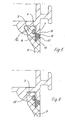
- Fig. 7 is the Isolierprofilfußabites 9 also on a wall 20 of the metal profiles. However, it has at the free end of the wall 20 a substantially perpendicular to the X-axis oriented projection 21, which serves for a secure, fail-safe engagement of the Isolierelfnfußes 9 in a correspondingly shaped recess 21 'of the metal profiles without the groove bottom 4' of Groove 4 is contacted at a gap width S greater than zero.
- a gap 12 is provided for the provided by the tolerances movement play of Isolierprofilfußes 9, a gap 12 is provided.
- Fig. 8 shows an insulating profile 22, in which the spring element 23 is laid on the opposite side to the inner web 24, ie, the spring element 23 now acts between the end face of the inner insulating strip 22 and the metal profile 1, 2 via the Nutsteg 24 (here in curved form ), on which the spring element 23 comes to rest.
- Fig. 9 shows a further variant of the invention, in which the spring element 25 is inserted into a groove or pocket 25 'in the end face 26 of the Isolierelfnfußes 9 and the gap S bridged. It may theoretically even fill the gap substantially or completely and / or be integrally formed on the insulating profile. Alternatively, the groove with the spring element can also be formed in the metal profile (not shown here).
- the described embodiments Fig. 3 to Fig. 9 have spring elements 14,23,25 which form a structural unit with the insulating profile 3, 8, 22, 27.
- the insulating profiles consist of a poorly heat-conductive plastic, especially of polyamide, PVC or the like, wherein the spring elements are preferably used in grooves or recesses on the insulating profile (or alternatively on the metal profile).
- the grooves can hold the spring elements positively or non-positively.
- the spring elements can also be arranged integrally on the insulating strips in a simple manner by coextrusion, gluing or the like.
- the shape of the spring elements 14, ... is not limited to the embodiments shown.
- the spring elements can also be formed in one piece with the insulating strip and (or identical to material - for example as spring sections in one-piece construction with the insulating profile), in which case the consistency of the spring elements can be different in terms of their hardness and compressibility.
- Fig. 10 shows a further detail of an engagement of the insulating strip in a corresponding receiving groove on the metal profiles.
- a recess or pocket 28 is inserted, on whose one groove side a strip-like spring tongue 29 is arranged.
- the pocket / groove 28 is dimensioned so that the spring tongue 29 is completely absorbed by the bag 28 in the case of abutment of the end face 26 at the groove bottom of the metal profiles.
- Fig. 11 shows that instead of the spring element 14 according to Fig. 5 a spring tongue 30 is provided on the shoulder 8 ", which is supported against the associated Anformsteg 7 of the respective metal profile 1, 2 and exerts the spring action with respect to the concerns of the metal profiles on the device limitations V1, V2.
- Fig. 12 shows a spring tongue 31 as a replacement of the spring element 23 according to Fig. 8 , which is resiliently supported against the middle, to the foot portion bent groove web 24 of the metal profiles.
- Fig. 13 shows a heat-insulated composite profile according to the invention with a (virtually unchanged from the outside) geometry of the type Fig. 1 in which the spring elements 14 are in their operative position between the metal profiles 1, 2 and the insulating profile 8 and form a structural unit with this.
- the spring elements 14 are provided according to this Fig. With a largely tear-resistant thread 32, which is then provided in the spring element, if this from a material-elastic material, such as rubber o. is to prevent stretching, to avoid deterioration of the spring characteristics of the spring element when mounting the spring element in the insulating profile.
- Fig. 14 shows a further embodiment of the invention, in which the at least one insulating profile 80 is integrally formed with an outer or inner profile section K made of plastic, so that according to either on the outside or on the inside of the composite profile no second metal profile is required. Also in this composite profile, an inventive gap S between the one metal profile 1, 2 and the insulating profile 80 is formed.
- the tolerance field can e.g. have the nominal size as the upper or lower limit; then the entire tolerance field is negative or positive.
- the nominal dimension can represent a value within the tolerance field, so that this results in a positive plus and a negative minus of the specified size.
- Fig. 2 This means that either all nominal dimensions are to be changed in accordance with the arrangement of the tolerance field, so that in each case at each end of the insulating profile, a gap S is formed. But you also have the opportunity. eg the nominal dimensions and the tolerance position according to Fig. 1 From the prior art, concerning the metal profiles to take over, but then the nominal size C of the insulating strip to be changed so that also the gap results in compensation of all tolerance fields between zero and a maximum.
- the width of the column S need not be set to the minimum of zero.
- a minimum gap can be defined with the gap thickness s (min) to which, in extreme cases, the tolerance fields of the three individual components are added, thus resulting in the total gap width s (max).
- the invention summarizes in a simple way the connection technology the profiles by a construction and an associated manufacturing process, in which the individual component tolerances no longer affect (or at least only to a small extent) on the overall depth G of the profile without the outer view of the composite profile changed significantly for the viewer becomes.
- the connection region of the plastic and metal profiles it is possible to reduce the nominal size of the overlapping composite profile, without it being necessary to change the nominal dimensions of the individual elements of the profile also.
Abstract
Description
Die Erfindung betrifft ein Verfahren nach dem Oberbegriff des Anspruchs 1 und ein wärmegedämmtes Verbundprofil nach dem Oberbegriff des Anspruchs 4.The invention relates to a method according to the preamble of claim 1 and a thermally insulated composite profile according to the preamble of
Ein Verbundprofil - welches sich hinsichtlich seiner wärmedämmenden Eigenschaften als wegweisend erwiesen hat - ist aus der
Die Herstellung des Verbundprofils folgt folgendem Schema. Zunächst werden die Metallprofile derart relativ zueinander gegeneinander ausgerichtet, dass sich die Isolierprofilaufnahmenuten gegenüberstchen. In die Aufnahmenuten werden dann die Isolierprofile eingeschoben bzw. eingelegt. Die Metallprofile werden sodann in einer Montagevorrichtung relativ zueinander ausgerichtet und gegeneinander verspannt, wobei die Spannkräfte auf die Außenflächen einwirken. Der Verbund wird dadurch fixiert, dass Stege an das Isolierprofil plastisch angefonnt werden.The production of the composite profile follows the following scheme. First, the metal profiles are aligned relative to each other against each other, that gegenüberstchen the Isolierprofilaufnahmenuten. In the grooves then the insulating profiles are inserted or inserted. The metal profiles are then aligned in a mounting device relative to each other and clamped against each other, the clamping forces acting on the outer surfaces. The composite is fixed in that webs are plastically angefonnt to the insulating profile.
Die Anformung der Stege kann mittels einer Montagevorrichtung erfolgen, bei der entweder das Profil durch die Vorrichtung bewegt wird oder aber die Vorrichtung über das ortsfeste Profil zur Anformung der Stege geführt wird.The Anformung the webs can be done by means of a mounting device in which either the profile is moved through the device or the device is guided over the stationary profile for forming the webs.
Das Bautiefenmaß bzw. die Bautiefe des gattungsgemäßen Verbundprofils berechnet sich als die Summe der hintereinander geschalteten Bautiefenmaße der einzelnen Elemente erstes Metallprofil, Isolierprofil und zweites Melallprofil. Es ergibt sich also nach dem Stand der Technik ein Bautiefenmaß, das von der Summe der Einzeltoleranzen überlagert wird. Eine genaue Beschreibung der Toleranzbedingungen des Profils der
Die Toleranzen der Metall- und Kunststoffprofile lassen sich herstellungsbedingt - im wesentlichen werden zur Herstellung die technisch komplexen Verfahren eines Strangpressens der Metallprofile bzw. eines Extrudierens der Kunststoffprofile (Isolierprofile) gewählt - über Mindestmaß nicht weiter einschränken, was bereits zu erheblichen Mehrkosten bei der Herstellung der Profile führt. Durch die Addition der Toleranzen der Einzelbauteile entstehen somit relativ große Abweichungen, die sich in der Praxis auf eine Gesamttoleranz g = ± 0,7 mm addieren können. Hinzukommen dann noch die bereits erwähnten Vorrichtungstoleranzen, die aber ohnehin sehr gering Ausfallen und sogar nahezu gegen Null gehen können.The tolerances of the metal and plastic profiles can be produced due to - are essentially for the production of technically complex processes of extruding the metal profiles or extruding the plastic profiles (insulating profiles) selected - not restrict beyond minimum, which already at considerable additional costs in the production of Profiles leads. The addition of the tolerances of the individual components thus results in relatively large deviations, which in practice can add up to a total tolerance g = ± 0.7 mm. Then there are the already mentioned device tolerances, which can be very low anyway and even go almost to zero.
Die wärmegedämmten Verbundprofile für Fenster, Türen und Fassaden werden zu Rahmen oder Riegel-/Pfosten-Konstruktionen zusammengefügt, bei denen die Profile auf Gehrung geschnitten werden oder stumpf aneinander anstoßen. Die großen Toleranzen der unterschiedlichen zueinander gebrachten Profile bedingen verschiedene Probleme. So ergibt sich durch die großen Toleranzen u.U. eine unsaubere Optik. Durch die Toleranzen können aber auch scharfkantig Profilschnitte entstehen, welche ein Verlectzungspotential beim Bedienen oder Reinigen mit sich bringen. Die Toleranzen bewirken neben diesen Effekten auch technische Schwierigkeiten in der Verbindertechnik bzw. bei der mechanischen Bearbeitung solcher Profile hinsichtlich des Sägens und Einfräsens von Beschlagteilen und Zubehör, sowie Funktionsmängel der fertigen Bauelemente (z.B. Undichtigkeiten, Schwergängigkeit usw.).The thermally insulated composite profiles for windows, doors and facades are assembled into frame or transom / post constructions in which the profiles are mitred or butt-jointed. The large tolerances of the different profiles brought together cause different problems. Thus, the large tolerances may result in an unclean appearance. Due to the tolerances, however, sharp-edged profile sections can also be created which entail a potential for entanglement during operation or cleaning. The tolerances cause in addition to these effects and technical difficulties in the connector technology or in the mechanical processing of such profiles in terms of sawing and milling of fittings and accessories, and functional defects of the finished components (eg leaks, stiffness, etc.).
Es ist zwar aus der gattungsgemäßen
Die Erfindung zielt angesichts dieser Problematik ausgehend von dem gattungsgemäβen Stand der Technik darauf ab, die Gesamttoleranz des Verbundprofils mit einfachen konstruktiven Mitteln zu verringern.In view of this problem, the invention aims, starting from the generic state of the art, to reduce the overall tolerance of the composite profile with simple structural means.
Die Erfindung erreicht dieses Ziel bzw. löst diese Aufgabe in Hinsicht auf das Verbundprofil durch den Gegenstand des Anspruches 4 und in Hinsicht auf das Verfahren durch den Gegenstand des Anspruchs 1.The invention achieves this object or solves this object with regard to the composite profile by the subject-matter of
Bei dem Verfahren zur Herstellung des Verbundprofils werden die Außenflächen der Metallprofile somit durch eine Montagevorrichtung auf dem Sollmaß G gehalten. Die in diesem Zustand von den Isolierprofilen eingenommene Lage innerhalb der Aufnahmenuten wird - z.B. auf einfache Weise durch Anformen der Stege in die Position eines Preßsitzes - fixiert und eingefroren. Damit erreicht die Gesamttoleranz in Bezug auf das Sollmaß G des Verbundprofils eine Größe, welche im wesentlichen der Vorrichtungstoleranz entspricht, obwohl die Einzeltoleranz der Metall- und Isolierprofile gegenüber dem Stand der Technik nicht eingeengt zu werden braucht, sondern vergrößert werden kann, was zur Vereinfachung des Herstellverfahrens der Einzelprofile und zu erheblicher Kostenreduzierung führt.In the method for producing the composite profile, the outer surfaces of the metal profiles are thus held by a mounting device on the specified dimension G. The position occupied by the insulating profiles in this state within the receiving grooves is - fixed and frozen - for example, in a simple manner by molding the webs in the position of a press fit. Thus, the total tolerance with respect to the nominal dimension G of the composite profile reaches a size which substantially corresponds to the device tolerance, although the individual tolerance of the metal and insulating profiles compared to the prior art need not be restricted, but can be increased, resulting in the simplification of Manufacturing process of individual profiles and significant cost reduction leads.
Dabei wird zwischen dem wenigstens einen Metallprofil und dem wenigstens einen Isolierprofil wenigstens ein Federelement und/oder ein elastisch komprimierbares Element angeordnet und/oder ausgebildet, welches vorzugsweise einstückig mit oder separat zu dem wenigstens einen Metallprofil und/oder dem wenigstens einen Isolierprofil ausgebildet ist. Nach einem Ausführungsbeispiel kann das elastisch komprimierbare Element auch in dem in dem wenigstens einen Spalt angeordnet sein und diesen ganz oder teilweise ausfüllen. Das Federelement muß derart dimensioniert werden, daß es das Isolierprofil und das Metallprofil so auseinander drückt, daß deren Außenseiten an der Montagevorrichtung anliegen oder zur Anlage kommen. Das Federelement kann - wie auch das elastisch komprimierbare Element - den Spalt auch teilweise oder ganz ausfüllen.In this case, at least one spring element and / or an elastically compressible element is arranged and / or formed between the at least one metal profile and the at least one insulating profile, which is preferably formed integrally with or separately from the at least one metal profile and / or the at least one insulating profile. According to one embodiment, the elastically compressible element may also be arranged in the at least one gap and fill it in whole or in part. The spring element must be dimensioned such that it presses apart the insulating profile and the metal profile so that their outer sides rest against the mounting device or come to rest. The spring element can - as well as the elastically compressible element - fill the gap also partially or completely.
Die Erfindung eignet sich für jedes Verbundprofil, bei dem wenigstens ein Kunststoff- und ein Metallprofil - insbesondere aus Leichtmetall wie Aluminium oder aus einer Aluminiumlegierung, aber auch Stahl - zu einem Verbundprofil zusammengefügt werden.The invention is suitable for any composite profile in which at least one plastic and one metal profile - in particular of light metal such as aluminum or of an aluminum alloy, but also steel - are joined together to form a composite profile.
Nachfolgend wird die Erfindung unter Bezug auf die beiliegende Zeichnung anhand von Ausführungsbeispielen näher beschrieben. Es zeigt:
- Fig. 1
- ein wärmegedämmtes Verbundprofil nach dem Stand der Technik;
- Fig. 2
- ein erfindungsgemäßes wärmegedämmtes Verbundprofil;
- Fig. 3-12
- den Verbindungsbereich zwischen einem Metallprofil und einem Isolier- profil in verschiedenen Montagestadien (
Fig. 2 ,3, 4 ) und/oder nach wei- teren Ausführungsbeispielen der Erfindung (Fig. 5 - 12 ), - Fig. 13
- ein weiteres erfindungsgemäßes wärmegedämmtes Verbundprotil; und
- Fig. 14
- ein weiteres erfindungsgemäßes wärmegedämmtes Verbundprofil aus einem Metallprofil und einem Isolierprofil mit einem direkt an dieses angeformten Außen- oder Innenprofil.
- Fig. 1
- a thermally insulated composite profile according to the prior art;
- Fig. 2
- a thermally insulated composite profile according to the invention;
- Fig. 3-12
- the connection area between a metal profile and an insulating profile in different assembly stages (
Fig. 2 .3, 4 ) and / or according to further embodiments of the invention (Fig. 5-12 ) - Fig. 13
- another thermally insulated composite protector according to the invention; and
- Fig. 14
- another inventive thermally insulated composite profile of a metal profile and an insulating profile with a molded directly to this outer or inner profile.
Anzumerken ist, dass die Fußabschnitte 9 relativ zur Haupterstreckungsebene der Isolierprofile zwischen den beiden Metallprofilen 1, 2 etwas parallel zur Haupterstrekkungsebene seitlich versetzt ausgebildet sind, so dass sich ein Absatz 3" ausbildet, welcher im wesentlichen direkt in der Erstreckungsebene des Steges 7 der Aufnahmenut 4 liegt. Druckkräfte in der Richtung der Erstreckungsebene der Isolierstege 3 werden somit nicht direkt über die Stirnseite der Stege 7 und die Isolierprofile 3, sondern aber über deren Fußabschnitte 9 abgeleitet.It should be noted that the
Die Fußabschnitte 9 der Isolierabschnitte sichern die Isolierstege 3 also gegen ein Herausfallen aus den Aufnahmenuten 4, wobei diese Sicherungswirkung gegen das Herausfallen durch einen Preßsitz des Isoliersteges 3 in der Aufnahmenut 4 erhöht wird, der dadurch realisiert wird, dass die äußeren Stege 7 beim Einsetzen der Isolierabschnitte 3 in die Aufnahmenuten 4 an die Isolierstege angeformt bzw. angepreßt werden. Alternativ (hier nicht dargestellt) können anstelle der äußeren Stege auch die inneren Stege anformbar ausgelegt sein.The
Die Herstellung des Isolierprofils folgt folgendem Schema. Zunächst werden die Metallprofile 1, 2 derart relativ zueinander gegeneinander ausgerichtet, dass sich die Isolierprofilaufnahmenuten 4 gegenüberstehen. In die Aufnahmenuten werden dann die Isolierprofile 3 eingeschoben bzw. eingelegt. Die Metallprofile 1, 2 werden sodann in einer Montagevorrichtung relativ zueinander ausgerichtet und gegeneinander verspannt, wobei die Spannkräfte auf die Außenflächen 5, 6 einwirken. Der Verbund wird dadurch fixiert, dass die äußeren Stege 7a an das Isolierprofil plastisch angeformt werden.The production of the insulating profile follows the following scheme. First, the
Die Anformung der Stege 7 kann mittels einer Montagevorrichtung erfolgen, bei der entweder das Verbundprofil durch die Vorrichtung bewegt wird oder aber die Vorrichtung über das ortsfeste Profil zur Anformung der Stege 7 geführt wird.The Anformung the
Das Bautiefenmaß bzw. die Bautiefe G berechnet sich als die Summe der hintereinander geschalteten Bautiefenmaße der einzelnen Elemente erstes Metallprofil 1(Bautiefenmaß A), Isolierprofil 3 (Bautiefenmaß C) und zweites Metallprofil 2 (Bautiefenmaß B). Es gilt also: ![]()
![]()
Das Bautiefenmaß G des Profils wird bei diesem Stand der Technik insbesondere dadurch bestimmt, dass die Isolierprofile 3 mit ihren Fuß-Stirnkanten im Nutgrund 4' der Aufnahmenuten 4 anliegen. Diese Konstruktion bedingt, dass sich auch die in der Praxis zwangsläufig auftretenden Toleranzen der einzelnen Profile 1, 2, 3 gegenüber ihrem Sollmaß gemeinsam mit der Toleranz der Montagevorrichtung zu einer Gesamttoleranz addieren. Es gilt: ![]()
wobei:
- g:=
- Gesamttoleranz des Verbundprofils in der Erstreckungsrichtung der drei hintereinander geschalteten
Profile - a:=
- Einzeltoleranz des Profils 1;
- b:=
Einzeltoleranz des Profils 2;- c:=
Einzeltoleranz des Profils 3- vt:=
- Vorrichtungstoleranz der Montagevorrichtung.
in which:
- g: =
- Total tolerance of the composite profile in the extension direction of the three consecutively
connected profiles - a: =
- Individual tolerance of the profile 1;
- b: =
- Individual tolerance of the
profile 2; - c: =
- Individual tolerance of the
profile 3 - vt: =
- Device tolerance of the mounting device.
Es ergibt sich also nach dem Stand der Technik ein Bautiefenmaß G, das von der Summe der Einzeltoleranzen a, b, c, vt überlagert wird.Thus, according to the state of the art, a basic depth G is obtained which is superimposed by the sum of the individual tolerances a, b, c, vt.
Die Vorrichtungstoleranz vt der Montagevorrichtung ist relativ klein gegenüber den Einzeltoleranzen der Isolierprofile 1, 2, 3. Es gilt daher in Näherung: ![]()
![]()
Die Einzeltoleranzen a, b, c ergeben sich jeweils aus der Summe der maximalen positiven Toleranzen +al, +b1, +c1 und der negativen Toleranzen -a2, -b2, -c2. Analoges gilt für die Gesamttoleranz g.The individual tolerances a, b, c result in each case from the sum of the maximum positive tolerances + al, + b1, + c1 and the negative tolerances -a2, -b2, -c2. The same applies to the total tolerance g.
Es gilt daher für die maximale positive Abweichung +g1 und die maximale negative Abweichung - g2 ![]()
![]()
![]()
![]()
Wie bereits erwähnt, erreichen + g1 und -g2 Werte von bis zu 0,7 mm.As already mentioned, + g1 and -g2 reach values of up to 0.7 mm.
Hier geht die Erfindung einen anderen, vorteilhafteren Weg.
Die maximale Spaltweite ergibt sich dann, wenn alle Einzelbauteile die maximale Minustoleranz erreichen, da sich das Summenspaltmaß s1 + s2 der Spalte S1 + S2 aus der Summe aller im konkreten Fall auftretenden positiven und negativen Toleranzen (Summe der Toleranzfelder) ergibt.The maximum gap width results when all individual components reach the maximum minus tolerance, since the sum gap dimension s1 + s2 of the column S1 + S2 results from the sum of all positive and negative tolerances occurring in the specific case (sum of the tolerance fields).
In dem Fall, dass die Einzelbauteile sämtlichst im maximalen Plustoleranzbereich liegen, geht die Summe aus den Spaltmaßen s1 und s2 der Spalte S1, S2 gegen Null. Es kann jedoch auch hier ein zusätzlicher (Mindest-)Spalt vorgesehen sein, der sich auch noch dann ergibt, wenn bereits alle Plustoleranzen ausgeschöpft wurden.In the event that the individual components are all in the maximum plus tolerance range, the sum of the gaps s1 and s2 of the column S1, S2 approaches zero. However, an additional (minimum) gap may also be provided here, which also results when all the plus tolerances have already been exhausted.
Im Ergebnis stellt sich auf diese Weise eine Gesamtbautiefe ein, die unabhängig von den Einzelbauteiltoleranzen ist und lediglich durch Vorrichtungstoleranzen vt beeinflußt wird, also gegen Null geht, wenn die Vorrichtungstoleranz vernachlässigbar klein ist.As a result, in this way, a total depth is established, which is independent of the individual component tolerances and is only influenced by device tolerances vt, ie, goes to zero, if the device tolerance negligible is small.
Eine Voraussetzung für die Durchführung des Verfahrens ist, dass das Isolierprofil 8, vorzugsweise dessen Isolierprofilfußabschnitt 9, relativ zu den Metallprofilen 1, 2 in Bautiefenrichtung G jeweils um den Betrag des Weges der halben maximalen negativen Gesamttoleranz -g2 in der Aufnahmenut 4 beweglich ist.A prerequisite for carrying out the method is that the insulating
Das heißt, dass der Isolierprofilfußabschnitt 9 im Regelfall - da sich die Gesamttoleranz nur selten auf die positive Gesamttoleranz einstellt - lediglich an einer parallel zur X-Ebene verlaufenden Fläche 10, 20 und/oder 11 des Hinterschnittes 7' zur Anlage kommt. Im Bereich des formschlüssigen Hintergriffes des Isolierprofilfußes 9 ist ein entsprechender Spalt 12 vorgesehen.This means that the
Nachfolgend wird die Montage des erfindungsgemäßen Verbundprofil beschrieben.The assembly of the composite profile according to the invention will be described below.
Bei dem Verfahren zur Herstellung des Verbundprofils sind die zueinander parallelen Außenflächen 5 und 6 der Profile 1 und 2 durch eine Montagevorrichtung auf dem Sollmaß G zu halten. Bei einer Montagevorrichtung mit ortsfesten Profilen kann dieses durch Spanneinrichtungen erfolgen. Die dann von den Isolierprofilen 8 eingenommene Lage innerhalb der Aufnahmenuten 4 wird durch Anformen der Stege 7 in die Position eines Preßsitzes fixiert und eingefroren. Damit erreicht die Gesamttoleranz G des Verbundprofils eine Größe, welche im wesentlichen der Vorrichtungstoleranz entspricht.In the method for producing the composite profile, the mutually parallel
Beim Durchlauf eines Verbundprofils durch eine stehende Montagevorrichtung ist es erforderlich, dass die Flächen 5 und 6 der Metallprofilschalen 1 und 2 während der Anformvorganges der Stege 7 an die Führungsrollen bzw. Führungsflächen der Vorrichtung angedrückt werden. Dieses kann z.B. auf einfache Weise durch Führungsrollen, die an außen liegenden Stegen angreifen, oder durch ein elastisches Federelement 13 (siehe
In den beiden zuvor beschriebenen Verfahren nehmen die Isolierprofile 8 in der Aufnahmenut 4 eine zufällige Lage ein, was zwei unterschiedliche Spaltmaße s1, s2 an einem Isolierprofil 8 zu Folge haben kann.In the two methods described above, the insulating
Ein Ausgleich der Spaltmaße s1, s2 der einander gegenüberliegenden Spalte S1, S2 durch ein Ausrichten des Isolierprofils 8 in einer mittleren Lage zwischen den Metallprofilen 1, 2 läßt sich durch zwei Federelemente 14a, 14b erreichen, die jeweils zwischen dem Metallprofil 1 und dem Isolierprofil 8 sowie zwischen dem Metallprofil 2 und dem Isolierprofil 8 - hier im wesentlichen zwischen der Stirnseite des Steges 7 und dem Absatz 8" des Isolierprofils - angeordnet sind. Neben der Zentrierung des Isolierprofils relativ zu den beiden Metallprofilen 1, 2 übernehmen die Federelemente 14 auch die Aufgabe des Auseinanderpressens der beiden Metallprofile 1, 2, so dass diese mit ihren Außenflächen oder Außenkanten 5, 6 an der Vorrichtungsbegrenzung anliegen. Ein separates Federelement 13 oder ein sonstiges Vorrichtungsmittel zum Auseinandertreiben der beiden Metallprofile ist damit nicht mehr notwendig. Die Federelemente 14 an dem Isolierprofil 8 ersetzen somit die Funktion eines Federelementes 13 bzw. besondere Haltevorrichtungen für die Metallprofile 1 und 2 an der Montagevorrichtung und realisieren damit eine besonders einfache und vorteilhafte Lösung der Erfindung.A compensation of the gaps s1, s2 of the opposite column S1, S2 by aligning the insulating
Die
Beim Durchlaufen der Vorrichtung werden die Federelemente 14 komprimiert, so dass sie eine Rückstellkraft auf die Metallprofile 1, 2 ausüben, welche die Anlage der Metallprofile 1 und 2 an der Vorrichtung selbst sicher stellt.When passing through the device, the
Das Federelement 14 besteht hier bevorzugt aus einem Kunststoff und wird derart ausgelegt, dass eine elastischfedernde oder formfedernde Wirkung gegeben ist. Es weist damit eine härtere Konsistenz als die Dichtungen 16 und 17 auf. Die Dichtungen 16 und 17 können einstückig mit dem Federelement 14 durch Koextrusion, Kleben oder auf sonstige Weise mechanisch verbunden sein. Die Dichtungen 16 und 17 weisen eine (vorzugsweise ausschließlich) für Dichtungsaufgaben geeignete weichere Konsistenz auf.The
Zum Beispiel kann das Federelement 14 aus einem gummiartigen Werkstoff wie APTK, Silikon oder ähnlichem mit einer Shorehärte von ca. 60 ausgeführt sein, während die einstückig angeordneten Dichtungen 16 und 17 eine geringere Shorehärte für die spezielle Aufgabe der Dichtung aufweisen.For example, the
Bei der Variante der
Die beschriebenen Ausführungen nach
Die Isolierprofile bestehen aus einem schlecht wärmeleitenden Kunststoff, vor allem aus Polyamid, PVC oder ähnlichem, wobei die Federelemente vorzugsweise in Nuten oder Aussparungen am Isolierprofil (oder alternativ am Metallprofil) eingesetzt werden. Die Nuten können die Federelemente form- oder kraftschlüssig halten. Die Federelemente können andererseits auch auf einfache Weise durch Koextrusion, Kleben oder ähnliches an den Isolierleisten einstückig angeordnet werden. Die Form der Federelemente 14, ... ist auf die dargestellten Ausführungen nicht beschränkt.The insulating profiles consist of a poorly heat-conductive plastic, especially of polyamide, PVC or the like, wherein the spring elements are preferably used in grooves or recesses on the insulating profile (or alternatively on the metal profile). The grooves can hold the spring elements positively or non-positively. On the other hand, the spring elements can also be arranged integrally on the insulating strips in a simple manner by coextrusion, gluing or the like. The shape of the
Die Federelemente können andererseits auch mit der Isolierleiste einstückig und (oder materialidentisch - z.B. als Federabschnitte in einstückiger Ausbildung mit dem Isolierprofil) ausgebildet werden, wobei dann die Konsistenz der Federelemente hinsichtlich ihrer Härte und Kompressibilität unterschiedlich sein kann.On the other hand, the spring elements can also be formed in one piece with the insulating strip and (or identical to material - for example as spring sections in one-piece construction with the insulating profile), in which case the consistency of the spring elements can be different in terms of their hardness and compressibility.
Das vorstehend Gesagte gilt auch für Profile, bei denen nicht die äußeren Profilstege 7 sondern die inneren Stege 7, 7b oder 24 angeformt (z.B. angepreßt, angerollt) werden und wenn die Federungen 29, 30, 31 an den Metallprofilen 1, 2 einstückig oder separat angeordnet sind (nicht dargestellt).The above also applies to profiles in which not the
Hinsichtlich der Toleranzen ist noch folgendes anzumerken. In der Regel geht man bei dem Vermaßen von Bauteilen von den sogenannten theoretischen Nennmaßen aus, die in der
Das Toleranzfeld kann z.B. das Nennmaß als Ober- bzw. Untergrenze haben; dann ergibt sich das gesamte Toleranzfeld ins Minus oder ins Plus.The tolerance field can e.g. have the nominal size as the upper or lower limit; then the entire tolerance field is negative or positive.
Das Nennmaß kann aber einen Wert innerhalb des Toleranzfeldes darstellen, so dass sich daraus eine Plusüberschreitung und eine Minusüberschreitung zum Sollmaß ergibt.However, the nominal dimension can represent a value within the tolerance field, so that this results in a positive plus and a negative minus of the specified size.
Für den vorliegenden Fall insbesondere nach
Für diese Fälle ergeben sich neue Nennmaße C und/oder A und B.For these cases new nominal dimensions C and / or A and B result.
Die Breite der Spalte S muß ferner nicht auf das Kleinstmaß Null festgelegt werden. Es kann grundsätzlich ein Minimalspalt definiert werden mit der Spaltdicke s(min), zu der sich im Extremfall die Toleranzfelder der drei Einzelbauteile hinzuaddieren und somit die Gesamtspaltbreite s(max) ergeben.Further, the width of the column S need not be set to the minimum of zero. In principle, a minimum gap can be defined with the gap thickness s (min) to which, in extreme cases, the tolerance fields of the three individual components are added, thus resulting in the total gap width s (max).
Die Erfindung verbessert zusammengefaßt auf einfache Weise die Verbindungstechnik der Profile durch eine Konstruktion und ein zugehöriges Herstellverfahren, bei der/dem sich die Einzelbauteiltoleranzen auf einfache Weise nicht mehr (oder zumindest nur in geringem Umfang) auf die Gesamtbautiefe G des Profils auswirken, ohne daß die äußere Ansicht des Verbundprofils für den Betrachter nennenswert geändert wird. Bereits durch eine einfache konstruktive Änderung im Verbindungsbereich der Kunststoff- und Metallprofile ist es vielmehr möglich, das Sollmaß des übergreifenden Verbundprofils zu verringern, ohne daß es notwendig wäre, die Sollmaße der Einzelelemente des Profils ebenfalls zu verändern.The invention summarizes in a simple way the connection technology the profiles by a construction and an associated manufacturing process, in which the individual component tolerances no longer affect (or at least only to a small extent) on the overall depth G of the profile without the outer view of the composite profile changed significantly for the viewer becomes. Already by a simple structural change in the connection region of the plastic and metal profiles, it is possible to reduce the nominal size of the overlapping composite profile, without it being necessary to change the nominal dimensions of the individual elements of the profile also.
Nachfolgend werden noch einige Formeln zur Erfindung und zum Stand der Technik zusammengestellt:A few formulas relating to the invention and to the prior art are summarized below:

- G = Vorrichtungstoleranz (gegen Null)G = device tolerance (towards zero)
-
S = 0

- erstes Metallprofilfirst metal profile
- 11
- zweites Metallprofilsecond metal profile
- 22
- Vorsprunghead Start
- 3'3 '
- Absatzparagraph
- 3 "3 "
- Isolierprofileinsulating profiles
- 3a, 3b3a, 3b
- IsolierprofilaufnahmenutenIsolierprofilaufnahmenuten
- 44
- Nutgrundgroove base
- 4'4 '
- Außenflächenexterior surfaces
- 5, 65, 6
- äußere Stegeouter bars
- 7a7a
- innerer Steginner jetty
- 7b7b
- Hinterschnittundercut
- 7'7 '
- Isolierprofilinsulating profile
- 88th
- Fußabschnittfoot section
- 99
- Flächensurfaces
- 10, 1110, 11
- Spaltgap
- 1212
- Federelementspring element
- 1313
- Federelementespring elements
- 14a, 14b14a, 14b
- gerändelter Drahtknurled wire
- 1515
- Dichtlippensealing lips
- 16, 1716, 17
- Anlagebereichplant area
- 18, 1918, 19
- Wandwall
- 2020
- Vorsprunghead Start
- 2121
- Ausnehmungrecess
- 21'21 '
- Isolierprofilinsulating profile
- 2222
- Federelementspring element
- 2323
- Nutsteggroove web
- 2424
- Federelementspring element
- 2525
- Nutgroove
- 25'25 '
- Stirnseitefront
- 2626
- Isolierprofilinsulating profile
- 2727
- Taschebag
- 2828
- Federzungespring tongue
- 2929
- Federzungespring tongue
- 30, 3130, 31
- Fadenthread
- 3232
- Isolierprofilinsulating profile
- 8080
- Kunststoff-ProfilabschnittPlastic profile section
- kk
- Nennmaßenominal dimensions
- A, B und CA, B and C
- Toleranzentolerances
- a, b, c, vta, b, c, vt
- Spaltdickegap thickness
- s, s1, s2s, s1, s2
- Spaltgap
- S, S1, S2S, S1, S2
- MontagevorrichtungsbegrenzungenMounting device limits
- V1, V2V1, V2
Claims (26)
- Method for producing a thermally insulated composite profile, in which- at least one metal profile (1), which has at least one insulating profile receiving groove (4) which comprises a groove bottom (4') and webs (7, 24) oriented at an angle to the groove bottom, and at least one insulating profile (8, 22, 27, 80) which engages in the insulating profile receiving groove (4) of the metal profile (1) are provided,- wherein the at least one metal profile (1) and the at least one insulating profile (8, 22, 27, 80) are oriented relative to one another in a mounting device in such a way that the outer sides of the profiles which face away from one another are spaced apart by a reference dimension,- wherein the position assumed by the at least one insulating profile (8, 22, 27, 80) is fixed within the insulating profile receiving groove (4),
characterized in that- the at least one metal profile (1) and the at least one insulating profile (8, 22, 27, 80) are pressed against guide surfaces or guide rollers of the mounting device by a spring element formed between the insulating profile and the metal profile or by an element which can be compressed elastically between the insulating profile and the metal profile,- while the position of the at least one metal profile (1) is fixed relative to the at least one insulating profile (8, 22, 27, 80) by forming or pressing the webs (7, 24) onto the at least one insulating profile (8, 22, 27, 80). - Method according to Claim 1, characterized in that a gap which spaces the insulating profile from the groove bottom is in each case formed between the bottom of the at least one insulating profile receiving groove and the at least one insulating profile (8, 22, 27, 80).
- Method according to either of the preceding claims 1 and 2, characterized in that the spring elements are stressed when passing through the mounting device such that they exert a force on the metal profile or profiles (1) which ensures that the metal profiles (1) bear against the mounting device.
- Thermally insulated composite profile, for windows, doors, facades or glazed roofs, comprising:- at least one metal profile (1) which has at least one insulating profile receiving groove (4) which has a groove bottom and webs (7, 24) oriented at an angle to the groove bottom, and- at least one insulating profile (8, 22, 27, 80) which engages in the insulating profile receiving groove (4) of the metal profile (1)- wherein a gap (S) is formed between the bottom of the at least one insulating profile receiving groove (4) and the at least one insulating profile (8, 22, 27, 80), and- wherein the position adopted by the at least one insulating profile (8, 22, 27, 80) is fixed within the receiving groove (4),- wherein the at least one metal profile and the at least one insulating profile are oriented relative to one another in such a way that the outer sides of the profiles which face away from one another are spaced apart by a reference dimension,- wherein the position of the at least one metal profile is fixed relative to the at least one insulating profile by forming or pressing the webs (7, 24) onto the at least one insulating profile (8, 22, 27, 80),
characterized in that- at least one spring element (14, 23, 25, 29, 30, 31) or an elastically compressible element is arranged and/or formed between the at least one metal profile (1, 2) and the at least one insulating profile (8, 22, 27, 80). - Composite profile according to Claim 4, characterized in that the at least one insulating profile (80) is formed in one piece from plastic with an outer or inner profile portion (K).
- Composite profile according to Claim 4 or 5, characterized in that the at least one spring element (14, 23, 25, 29, 30, 31) and/or the elastically compressible element is formed in one piece with or separately from the at least one metal profile (1, 2) and/or the at least one insulating profile (8, 22, 27, 80).
- Composite profile according to one of the preceding Claims 4 to 6, characterized in that the elastically compressible element (25, 29) is arranged in the at least one gap (S1, S2).
- Composite profile according to one of the preceding Claims 4 to 7, characterized in that the spring element (25, 29) is inserted into a pocket (25') in the end side (26) of an insulating profile foot (9) or of the metal profile (1, 2) and bridges the gap (S).
- Composite profile according to Claim 8, characterized in that the pocket (25') is let at the end side (26) into the insulating profile foot (9) or in the metal profile and is dimensioned in such a way that, in the case where the end side (26) of the insulating profile (8, 22, 27, 80) bears against the groove bottom (4') of the metal profile (1, 2), the spring element (29) is completely accommodated by the pocket (25', 28).
- Composite profile according to one of the preceding Claims 4 to 9, characterized in that the spring element is formed as a strip-like spring tongue (29, 30, 31).
- Composite profile according to Claim 10, characterized in that the spring tongue (29, 30, 31) is supported against a web (7, 24) or the groove bottom (4') of the metal profile (1, 2).
- Composite profile according to one of the preceding Claims 8 to 11, characterized in that at least one of the webs (7, 24) forms, on its side facing the insulating profile receiving groove (4), an undercut (7') in which a projection of the insulating profile foot (9) engages.
- Composite profile according to Claim 12, characterized in that an intermediate gap (12) is formed in the region of the form-fitting undercut of the insulating profile foot (9).
- Composite profile according to one of the preceding Claims 8 to 13, characterized in that the insulating profile foot (9) is formed onto the at least one insulating profile (3, 8, 22, 27, 80) via a shoulder (8") which lies substantially directly in a plane of extension of one of the webs (7, 24) of the insulating profile receiving groove (4) and bears against this web (7, 24) via the spring element.
- Composite profile according to one of the preceding Claims 8 to 14, characterized in that a toothed or knurled wire (15) is in each case arranged between the insulating profile (8, 80) and the at least one metal profile (1, 2).
- Composite profile according to Claim 15, characterized in that the wire (15) is substantially arranged in a recess of the insulating profile foot (9) and, on a portion of its outer circumference, produces a form fit with one of the webs (7, 24) in the longitudinal direction of the metal profile (1, 2).
- Composite profile according to one of the preceding Claims 4 to 16, characterized in that the spring element (13, 23, 25) consists of a rubber-like material such as APTK, silicone etc.
- Composite profile according to one of the preceding Claims 4 to 17, characterized in that the spring element (14, 23, 25) has a Shore hardness of approximately 60.
- Composite profile according to one of the preceding Claims 4 to 18, characterized in that the spring element (14, 23, 25) has a tear-resistant thread (32).
- Composite profile according to one of the preceding Claims 4 to 19, characterized in that the metal profile (1, 2) is formed as a lightweight metal profile.
- Composite profile according to one of the preceding Claims 4 to 20, characterized in that it comprises two metal profiles (1, 2), wherein the at least one insulating profile (8, 22, 27, 80) is arranged between the two metal profiles (1, 2), wherein a gap (S2, S2) and a spring element are in each case provided between the two metal profiles (1, 2) and the at least one insulating profile (8, 22, 27, 80).
- Composite profile according to Claim 21, characterized in that the dimensions of the two gaps (S1, S2) are substantially identical.
- Composite profile according to either of the preceding Claims 21 and 22, characterized in that the gap widths s1, s2 of the gaps (S1, S2) satisfy the following condition:

where:s:= Total gap width of the two gapss1, s2:= Individual width of the gaps S1 and S2g:= Overall tolerance of the composite profile in the direction of extension of the three series-connected profiles 1, 2, 8.a:= Individual tolerance of the profile 1;b:= Individual tolerance of the profile 2;c:= Individual tolerance of the profile 8. - Composite profile according to Claim 23, characterized in that, with a maximum individual tolerance of all the individual profiles in the plus tolerance range, the sum of the gap dimensions (s1 and s2) of the gaps (S1, S2) is greater than zero.
- Composite profile according to one of the preceding Claims 21 to 24, characterized in that sealing elements which are separate or connected to the insulating or metal profile (1, 2, 8) are formed between the metal profiles (1, 2) and the insulating profile (8, 22, 27, 80).
- Composite profile according to one of the preceding Claims 21 to 25, characterized in that the respective one spring element (14) has, in the bearing region (19) with the insulating profile (8, 22, 27, 80) and in each case in the bearing region (18) with the metal profiles (1, 2), sealing lips (16, 17) which consist of a softer material than the remaining spring element (14).
Applications Claiming Priority (3)
| Application Number | Priority Date | Filing Date | Title |
|---|---|---|---|
| DE10015986A DE10015986C2 (en) | 2000-03-31 | 2000-03-31 | Composite profile and method for producing a composite profile |
| DE10015986 | 2000-03-31 | ||
| PCT/EP2001/003396 WO2001075259A1 (en) | 2000-03-31 | 2001-03-26 | Composite profile and method for producing a composite profile |
Publications (2)
| Publication Number | Publication Date |
|---|---|
| EP1268968A1 EP1268968A1 (en) | 2003-01-02 |
| EP1268968B1 true EP1268968B1 (en) | 2011-05-11 |
Family
ID=7637078
Family Applications (1)
| Application Number | Title | Priority Date | Filing Date |
|---|---|---|---|
| EP01933750A Expired - Lifetime EP1268968B1 (en) | 2000-03-31 | 2001-03-26 | Composite profile and method for producing a composite profile |
Country Status (21)
| Country | Link |
|---|---|
| US (1) | US7165367B2 (en) |
| EP (1) | EP1268968B1 (en) |
| JP (1) | JP4898058B2 (en) |
| CN (1) | CN1177124C (en) |
| AT (1) | ATE509174T1 (en) |
| AU (1) | AU2001260151A1 (en) |
| CA (1) | CA2399546C (en) |
| CZ (1) | CZ20023239A3 (en) |
| DE (1) | DE10015986C2 (en) |
| EA (1) | EA003650B1 (en) |
| EE (1) | EE05041B1 (en) |
| HK (1) | HK1054259B (en) |
| HR (1) | HRP20020788B1 (en) |
| HU (1) | HUP0204396A2 (en) |
| IL (1) | IL151067A0 (en) |
| NO (1) | NO318478B1 (en) |
| PL (1) | PL357953A1 (en) |
| SK (1) | SK13222002A3 (en) |
| TR (1) | TR200201945T2 (en) |
| UA (1) | UA75354C2 (en) |
| WO (1) | WO2001075259A1 (en) |
Families Citing this family (18)
| Publication number | Priority date | Publication date | Assignee | Title |
|---|---|---|---|---|
| FR2836497B1 (en) * | 2002-02-22 | 2004-11-05 | Virtual Travel | DEVICE FOR FIXING AN ACOUSTIC PANEL ON A WALL |
| DE10210968C1 (en) * | 2002-03-13 | 2003-06-18 | Edscha Cabrio Dachsys Gmbh | Extruded profile for motor vehicle sliding roof has two interlocking rails section with projecting strip on one engaging correspondingly shaped recess in other |
| DE20304745U1 (en) * | 2003-03-24 | 2003-06-05 | Schueco Int Kg | Frame profile for a solar collector |
| US6789369B1 (en) * | 2003-04-03 | 2004-09-14 | Monarch Manufacturing Company | Composite window frame structural member |
| DE10331382A1 (en) * | 2003-07-11 | 2005-02-03 | SCHÜCO International KG | Composite profile with insulating bar, especially for windows, doors and facades |
| US20080016816A1 (en) * | 2006-07-19 | 2008-01-24 | Do Yeon Kim | Beam/Column With Stiffening Stick |
| US7600350B2 (en) * | 2006-09-21 | 2009-10-13 | Ykk Corporation Of America | Thermally broken sunshade anchors |
| US7849638B2 (en) | 2006-09-21 | 2010-12-14 | Ykk Corporation Of America | Sunshades and methods of installing sunshades |
| DE102006061035C5 (en) * | 2006-12-22 | 2014-09-04 | Technoform Bautec Holding Gmbh | Plastic profile for window, door and facade elements |
| ITBO20070243A1 (en) * | 2007-04-03 | 2008-10-04 | Gsg Int Spa | ACCESSORY FOR PROFILES FOR SLIDING DOORS. |
| ITMI20071932A1 (en) * | 2007-10-05 | 2009-04-06 | Norsk Hydro As | HALF-SHAPED TO MAKE THERMAL OR SIMILAR CUTTING WINDOWS, RELATED PROFILE AND RELATIVE ASSEMBLY PROCESS |
| US20100223870A1 (en) * | 2009-03-04 | 2010-09-09 | Cincinnati Thermal Spray Inc. | Structural Member and Method of Manufacturing Same |
| US20110318094A1 (en) * | 2010-06-29 | 2011-12-29 | Vincent Hensley | Strut for connecting frames |
| US8833025B2 (en) * | 2011-01-04 | 2014-09-16 | Advanced Architectural Products, Llc | Polymer-based bracket system for exterior cladding |
| US9175881B2 (en) * | 2013-04-29 | 2015-11-03 | Sunmodo Corporation | Thermal expansion compensation apparatus for mounting solar panels |
| PL3140484T3 (en) * | 2014-05-05 | 2019-08-30 | SCHÜCO International KG | Composite profiled section for doors, windows, or facade elements |
| DE102014106226A1 (en) * | 2014-05-05 | 2015-11-05 | SCHÜCO International KG | Composite profile for doors, windows or façade elements |
| CN113931494B (en) * | 2021-11-25 | 2023-07-25 | 安徽克琳黛尔智能家居有限公司 | Profile connecting structure with gap adjusting function and shower room |
Family Cites Families (44)
| Publication number | Priority date | Publication date | Assignee | Title |
|---|---|---|---|---|
| US3393487A (en) * | 1966-10-06 | 1968-07-23 | Reynolds Metals Co | Thermally insulating joint construction |
| US3517472A (en) * | 1967-05-08 | 1970-06-30 | Anchor Enterprises Corp | Structural element with thermal barrier means |
| US3925953A (en) * | 1974-04-08 | 1975-12-16 | Ethyl Corp | Method of making a thermal break construction element |
| DE7507260U (en) * | 1975-03-07 | 1976-01-29 | Nahr, Helmar, Dr., 8530 Neustadt | A BODY COMPOSED FROM AT LEAST TWO PARTIAL BODIES |
| NO139976C (en) * | 1975-03-07 | 1979-06-13 | Helmar Nahr | BODY COMPOSED OF AT LEAST TWO PARTS |
| DE2552700C2 (en) * | 1975-11-25 | 1980-06-19 | Otto Fuchs Kg, 5882 Meinerzhagen | Composite profile, especially for windows, doors and facades |
| DE2660436C3 (en) * | 1976-02-28 | 1982-01-14 | Plastic-Werk A. U. G. Scherer & Trier Ohg, 8626 Michelau | Composite profile, especially for windows, doors, facades or the like. |
| FR2363720A1 (en) * | 1976-08-31 | 1978-03-31 | Hasselbacher Wilhelm | BINDING TAPE FOR TWO METAL PIECES |
| US4164830A (en) * | 1977-12-16 | 1979-08-21 | Bierlich J H | Double-glazed doors or windows and frame assemblies therefor |
| DE2821096A1 (en) * | 1978-05-13 | 1979-11-15 | Scherer Plastic Werk | Profiled strip for mfr. of window and door frames - is composed of metal profiles enclosing plastics insulating packing, fitted with locking cams and corresp. cut=outs for permanent assembly |
| DE2826874C2 (en) * | 1978-06-19 | 1986-07-31 | Helmar Dr.Dr. 8530 Neustadt Nahr | Composite profile as well as methods and tools for its production |
| DE7821041U1 (en) * | 1978-07-13 | 1982-05-19 | Technoform, Caprano + Brunnhofer KG, 3501 Fuldabrück | PROFILE ROD UNIT |
| DE2908950A1 (en) * | 1979-03-07 | 1980-09-18 | Schuermann & Co Heinz | METHOD FOR PRODUCING A HEAT-INSULATED DOOR LEAF AND DOOR LEAF FRAME |
| JPS601180Y2 (en) * | 1979-06-18 | 1985-01-14 | 三井軽金属加工株式会社 | insulation profile |
| JPS56888A (en) * | 1979-06-19 | 1981-01-07 | Nippon Kokan Kk <Nkk> | Reforming of heavy oil |
| DE2937454C2 (en) * | 1979-09-15 | 1985-08-08 | SCHÜCO Heinz Schürmann GmbH & Co, 4800 Bielefeld | Composite profile, in particular for windows, doors and facades, and a method for producing the composite profile |
| US4333295A (en) * | 1980-05-22 | 1982-06-08 | Hef-Fenstertechnik Vetriebs Gmbh | Casement frame |
| DE3033206C2 (en) * | 1980-09-03 | 1984-07-05 | Josef Gartner & Co, 8883 Gundelfingen | Composite profile |
| DE3035526C2 (en) * | 1980-09-19 | 1985-04-18 | Helmar Dr.Dr. 8530 Neustadt Nahr | Profile body |
| CA1164620A (en) * | 1981-10-07 | 1984-04-03 | Francois X. Laroche | Structural members modules |
| DE3229230C2 (en) * | 1982-08-05 | 1984-06-28 | Otto Dipl.-Ing. 8784 Burgsinn Willert | Composite profile |
| DE3372005D1 (en) * | 1982-08-05 | 1987-07-16 | Otto Willert | Compound profile |
| SE8205119L (en) * | 1982-09-09 | 1984-03-10 | Integral Profilsystem Ab | INSULATION OF ALUMINUM PROFILES IN FIXTURE |
| DE3245078A1 (en) * | 1982-12-06 | 1984-06-07 | Helmar Dr.Dr. 8530 Neustadt Nahr | Intermediate product for a compound profile intended especially for the production of window or door frames, process for its production, process for the production of a compound profile from the intermediate product and separating device for implementing the latter process |
| DE3300599C3 (en) * | 1983-01-11 | 1994-08-11 | Gartner & Co J | Composite profile |
| DE3319262C1 (en) * | 1983-05-27 | 1984-05-24 | SCHÜCO Heinz Schürmann GmbH & Co, 4800 Bielefeld | Device for connecting the parts of a heat-insulated composite profile |
| DE3342700A1 (en) * | 1983-07-06 | 1985-01-17 | Helmar Dr.Dr. 8530 Neustadt Nahr | METHOD FOR PRODUCING A HEAT-INSULATING PROFILE BODY |
| DE3330391A1 (en) * | 1983-08-23 | 1985-03-21 | Hosta-Metallbau, 8400 Regensburg | Composite profile, in particular for windows, doors or façades |
| DE3332618A1 (en) * | 1983-09-09 | 1985-03-21 | Josef Gartner & Co, 8883 Gundelfingen | COMPOSITE PROFILE |
| DE3343687A1 (en) * | 1983-11-30 | 1985-06-05 | Schweizerische Aluminium Ag, Chippis | METAL FRAME CONSTRUCTION FOR WINDOWS OR DOORS |
| DE3440710A1 (en) * | 1984-11-07 | 1986-05-07 | Theodor 8857 Gottmannshofen Straub | Process for producing aluminium insulating profiles |
| DE3514538C1 (en) * | 1985-03-18 | 1986-08-14 | Josef Gartner & Co, 8883 Gundelfingen | Composite profile |
| US4704839A (en) * | 1985-12-06 | 1987-11-10 | Products Research & Chemical Corporation | Thermal barrier extrusion |
| DE3603507A1 (en) * | 1986-02-05 | 1987-08-06 | Erbsloeh Julius & August | Positively locking connection of two parts |
| DE3939968A1 (en) * | 1989-12-02 | 1991-06-06 | Schueco Int Gmbh & Co | COMPOSITE PROFILE, ESPECIALLY FOR WINDOWS, DOORS AND FACADES |
| US5469683A (en) * | 1994-02-09 | 1995-11-28 | Kawneer Company, Inc. | Thermally insulating composite frame member with snap-in thermal isolator |
| DE19637858A1 (en) * | 1996-09-17 | 1998-04-02 | Schueco Int Kg | Insulated composite profile for doors, windows or facades |
| DE19643681C2 (en) * | 1996-10-23 | 1999-12-30 | Caprano & Brunnhofer | Composite profile element with at least one metal profile rod and at least one plastic profile section |
| IT1290075B1 (en) * | 1997-03-13 | 1998-10-19 | Me Tra Metallurg Trafilati All | STRUCTURE OF ALUMINUM PROFILES WITH THERMAL BRIDGE INTERRUPTION PARTICULARLY DESIGNED FOR WINDOWS AND SIMILAR |
| CA2294426C (en) * | 1997-06-19 | 2006-08-15 | Keith Owen Lewcock | Improvements relating to structural framework systems |
| JPH1162390A (en) * | 1997-08-19 | 1999-03-05 | Tostem Corp | Thermal insulating formed material |
| DE29810183U1 (en) * | 1998-05-14 | 1999-09-23 | Caprano & Brunnhofer | Composite profile for frames of windows, doors, facade elements, etc., IR reflective tape, in particular for this composite profile and use of the IR reflective tape in the composite profile |
| US6668500B1 (en) * | 1999-05-26 | 2003-12-30 | Glasfabrik Lamberts Gmbh & Co. Kg | Holding rail for holding glass profile elements |
| GB2368442A (en) * | 2000-10-27 | 2002-05-01 | Ncr Int Inc | Adaptive alteration of charges for use of an automatic teller machine |
-
2000
- 2000-03-31 DE DE10015986A patent/DE10015986C2/en not_active Expired - Fee Related
-
2001
- 2001-03-26 EP EP01933750A patent/EP1268968B1/en not_active Expired - Lifetime
- 2001-03-26 HU HU0204396A patent/HUP0204396A2/en unknown
- 2001-03-26 SK SK1322-2002A patent/SK13222002A3/en unknown
- 2001-03-26 CA CA002399546A patent/CA2399546C/en not_active Expired - Fee Related
- 2001-03-26 EE EEP200200449A patent/EE05041B1/en not_active IP Right Cessation
- 2001-03-26 PL PL01357953A patent/PL357953A1/en not_active IP Right Cessation
- 2001-03-26 AT AT01933750T patent/ATE509174T1/en active
- 2001-03-26 JP JP2001572721A patent/JP4898058B2/en not_active Expired - Fee Related
- 2001-03-26 EA EA200200999A patent/EA003650B1/en not_active IP Right Cessation
- 2001-03-26 AU AU2001260151A patent/AU2001260151A1/en not_active Abandoned
- 2001-03-26 WO PCT/EP2001/003396 patent/WO2001075259A1/en active Application Filing
- 2001-03-26 IL IL15106701A patent/IL151067A0/en unknown
- 2001-03-26 TR TR2002/01945T patent/TR200201945T2/en unknown
- 2001-03-26 CZ CZ20023239A patent/CZ20023239A3/en unknown
- 2001-03-26 CN CNB01805367XA patent/CN1177124C/en not_active Expired - Fee Related
- 2001-03-26 UA UA2002108641A patent/UA75354C2/en unknown
-
2002
- 2002-09-27 NO NONO/SPC/2A patent/NO318478B1/en not_active IP Right Cessation
- 2002-09-27 US US10/256,385 patent/US7165367B2/en not_active Expired - Fee Related
- 2002-09-30 HR HR20020788A patent/HRP20020788B1/en not_active IP Right Cessation
-
2003
- 2003-09-11 HK HK03106494.5A patent/HK1054259B/en not_active IP Right Cessation
Also Published As
| Publication number | Publication date |
|---|---|
| UA75354C2 (en) | 2006-04-17 |
| HRP20020788A2 (en) | 2003-12-31 |
| JP2003529693A (en) | 2003-10-07 |
| NO20024636D0 (en) | 2002-09-27 |
| PL357953A1 (en) | 2004-08-09 |
| AU2001260151A1 (en) | 2001-10-15 |
| CN1177124C (en) | 2004-11-24 |
| CA2399546C (en) | 2008-07-15 |
| EA003650B1 (en) | 2003-08-28 |
| NO318478B1 (en) | 2005-03-21 |
| SK13222002A3 (en) | 2003-10-07 |
| DE10015986C2 (en) | 2002-08-01 |
| HRP20020788B1 (en) | 2004-06-30 |
| TR200201945T2 (en) | 2003-01-21 |
| WO2001075259B1 (en) | 2002-03-07 |
| WO2001075259A1 (en) | 2001-10-11 |
| DE10015986A1 (en) | 2001-10-18 |
| EE05041B1 (en) | 2008-06-16 |
| EE200200449A (en) | 2003-12-15 |
| CA2399546A1 (en) | 2001-10-11 |
| JP4898058B2 (en) | 2012-03-14 |
| HUP0204396A2 (en) | 2003-06-28 |
| IL151067A0 (en) | 2003-04-10 |
| HK1054259A1 (en) | 2003-11-21 |
| US20030019184A1 (en) | 2003-01-30 |
| EA200200999A1 (en) | 2003-02-27 |
| CN1416496A (en) | 2003-05-07 |
| NO20024636L (en) | 2002-09-27 |
| CZ20023239A3 (en) | 2003-03-12 |
| US7165367B2 (en) | 2007-01-23 |
| EP1268968A1 (en) | 2003-01-02 |
| ATE509174T1 (en) | 2011-05-15 |
| HK1054259B (en) | 2005-04-08 |
Similar Documents
| Publication | Publication Date | Title |
|---|---|---|
| EP1268968B1 (en) | Composite profile and method for producing a composite profile | |
| EP0614018A2 (en) | T connection between two profiles | |
| DE4404348A1 (en) | Process for the production and installation of a glass pane with a frame, in particular on a vehicle part | |
| EP1643049B1 (en) | Construction with structural profiles | |
| DE202005021480U1 (en) | Fasteners for plates, in particular of glass, for fixing the same and thus equipped plates | |
| DE3728247C1 (en) | Composite profile for frame legs or rungs | |
| DE3003367A1 (en) | KIT FOR THE PRODUCTION OF FRAME FOR BODIES | |
| EP1144882B1 (en) | Linear displacement guide | |
| EP1992779A2 (en) | Pull-out profile for window shades | |
| DE2606614A1 (en) | FRAME FOR A WINDOW OR DOOR LEAF | |
| DE10119446B4 (en) | Window or door frame | |
| DE3738358A1 (en) | Frame, in particular for lightweight windows, secondary windows, flyscreens or the like | |
| DE10207157A1 (en) | Connecting component for face-side connection of two parts, of which at least one part is movable and other is static, is arranged on face side of parts to be connected and provided with hollow chamber | |
| DE102014114909A1 (en) | profile connector | |
| DE3330391A1 (en) | Composite profile, in particular for windows, doors or façades | |
| DE2507393B2 (en) | FRAME FOR A SLIDING DOOR OR A SLIDING WINDOW | |
| DE8017253U1 (en) | DEVICE FOR Roughening, ESPECIALLY KNURLING, INSIDE RIDGE AREAS OF COMPOSITE PROFILES FOR WINDOWS AND THE LIKE | |
| DE202007008187U1 (en) | Excerpt profile for window panel | |
| DE2249541A1 (en) | GLASS BRACKETS, IN PARTICULAR FOR WINDOWS AND DOORS | |
| DE102018000141B4 (en) | Hand tool for mounting sealing profiles | |
| EP1262622A2 (en) | Underlying structural member | |
| EP1223350A2 (en) | Clamping holder for elements in form of a plate | |
| AT17518U1 (en) | Sealing element and window sill system | |
| DE202004009645U1 (en) | Sealing profile made of an inorganic elastomer | |
| AT405805B (en) | Sliding window |
Legal Events
| Date | Code | Title | Description |
|---|---|---|---|
| PUAI | Public reference made under article 153(3) epc to a published international application that has entered the european phase |
Free format text: ORIGINAL CODE: 0009012 |
|
| 17P | Request for examination filed |
Effective date: 20020706 |
|
| AK | Designated contracting states |
Kind code of ref document: A1 Designated state(s): AT BE CH CY DE DK ES FI FR GB GR IE IT LI LU MC NL PT SE TR |
|
| AX | Request for extension of the european patent |
Free format text: AL;LT PAYMENT 20020706;LV PAYMENT 20020706;MK PAYMENT 20020706;RO;SI PAYMENT 20020706 |
|
| 17Q | First examination report despatched |
Effective date: 20080422 |
|
| GRAP | Despatch of communication of intention to grant a patent |
Free format text: ORIGINAL CODE: EPIDOSNIGR1 |
|
| GRAS | Grant fee paid |
Free format text: ORIGINAL CODE: EPIDOSNIGR3 |
|
| GRAA | (expected) grant |
Free format text: ORIGINAL CODE: 0009210 |
|
| AK | Designated contracting states |
Kind code of ref document: B1 Designated state(s): AT BE CH CY DE DK ES FI FR GB GR IE IT LI LU MC NL PT SE TR |
|
| AX | Request for extension of the european patent |
Extension state: LT LV MK SI |
|
| REG | Reference to a national code |
Ref country code: GB Ref legal event code: FG4D Free format text: NOT ENGLISH |
|
| REG | Reference to a national code |
Ref country code: CH Ref legal event code: NV Representative=s name: ISLER & PEDRAZZINI AG Ref country code: CH Ref legal event code: EP |
|
| REG | Reference to a national code |
Ref country code: IE Ref legal event code: FG4D |
|
| REG | Reference to a national code |
Ref country code: DE Ref legal event code: R096 Ref document number: 50115877 Country of ref document: DE Effective date: 20110622 |
|
| REG | Reference to a national code |
Ref country code: NL Ref legal event code: T3 |
|
| LTIE | Lt: invalidation of european patent or patent extension |
Effective date: 20110511 |
|
| PG25 | Lapsed in a contracting state [announced via postgrant information from national office to epo] |
Ref country code: SE Free format text: LAPSE BECAUSE OF FAILURE TO SUBMIT A TRANSLATION OF THE DESCRIPTION OR TO PAY THE FEE WITHIN THE PRESCRIBED TIME-LIMIT Effective date: 20110511 Ref country code: PT Free format text: LAPSE BECAUSE OF FAILURE TO SUBMIT A TRANSLATION OF THE DESCRIPTION OR TO PAY THE FEE WITHIN THE PRESCRIBED TIME-LIMIT Effective date: 20110912 |
|
| PG25 | Lapsed in a contracting state [announced via postgrant information from national office to epo] |
Ref country code: CY Free format text: LAPSE BECAUSE OF FAILURE TO SUBMIT A TRANSLATION OF THE DESCRIPTION OR TO PAY THE FEE WITHIN THE PRESCRIBED TIME-LIMIT Effective date: 20110511 Ref country code: GR Free format text: LAPSE BECAUSE OF FAILURE TO SUBMIT A TRANSLATION OF THE DESCRIPTION OR TO PAY THE FEE WITHIN THE PRESCRIBED TIME-LIMIT Effective date: 20110812 Ref country code: ES Free format text: LAPSE BECAUSE OF FAILURE TO SUBMIT A TRANSLATION OF THE DESCRIPTION OR TO PAY THE FEE WITHIN THE PRESCRIBED TIME-LIMIT Effective date: 20110822 Ref country code: FI Free format text: LAPSE BECAUSE OF FAILURE TO SUBMIT A TRANSLATION OF THE DESCRIPTION OR TO PAY THE FEE WITHIN THE PRESCRIBED TIME-LIMIT Effective date: 20110511 |
|
| REG | Reference to a national code |
Ref country code: IE Ref legal event code: FD4D |
|
| PG25 | Lapsed in a contracting state [announced via postgrant information from national office to epo] |
Ref country code: IE Free format text: LAPSE BECAUSE OF FAILURE TO SUBMIT A TRANSLATION OF THE DESCRIPTION OR TO PAY THE FEE WITHIN THE PRESCRIBED TIME-LIMIT Effective date: 20110511 |
|
| PG25 | Lapsed in a contracting state [announced via postgrant information from national office to epo] |
Ref country code: DK Free format text: LAPSE BECAUSE OF FAILURE TO SUBMIT A TRANSLATION OF THE DESCRIPTION OR TO PAY THE FEE WITHIN THE PRESCRIBED TIME-LIMIT Effective date: 20110511 |
|
| PLBE | No opposition filed within time limit |
Free format text: ORIGINAL CODE: 0009261 |
|
| STAA | Information on the status of an ep patent application or granted ep patent |
Free format text: STATUS: NO OPPOSITION FILED WITHIN TIME LIMIT |
|
| 26N | No opposition filed |
Effective date: 20120214 |
|
| REG | Reference to a national code |
Ref country code: DE Ref legal event code: R097 Ref document number: 50115877 Country of ref document: DE Effective date: 20120214 |
|
| PG25 | Lapsed in a contracting state [announced via postgrant information from national office to epo] |
Ref country code: MC Free format text: LAPSE BECAUSE OF NON-PAYMENT OF DUE FEES Effective date: 20120331 |
|
| PG25 | Lapsed in a contracting state [announced via postgrant information from national office to epo] |
Ref country code: TR Free format text: LAPSE BECAUSE OF FAILURE TO SUBMIT A TRANSLATION OF THE DESCRIPTION OR TO PAY THE FEE WITHIN THE PRESCRIBED TIME-LIMIT Effective date: 20110511 |
|
| PGFP | Annual fee paid to national office [announced via postgrant information from national office to epo] |
Ref country code: NL Payment date: 20140320 Year of fee payment: 14 Ref country code: CH Payment date: 20140324 Year of fee payment: 14 |
|
| PG25 | Lapsed in a contracting state [announced via postgrant information from national office to epo] |
Ref country code: LU Free format text: LAPSE BECAUSE OF NON-PAYMENT OF DUE FEES Effective date: 20120326 |
|
| PGFP | Annual fee paid to national office [announced via postgrant information from national office to epo] |
Ref country code: AT Payment date: 20140320 Year of fee payment: 14 Ref country code: FR Payment date: 20140319 Year of fee payment: 14 Ref country code: IT Payment date: 20140328 Year of fee payment: 14 |
|
| PGFP | Annual fee paid to national office [announced via postgrant information from national office to epo] |
Ref country code: GB Payment date: 20140324 Year of fee payment: 14 |
|
| PGFP | Annual fee paid to national office [announced via postgrant information from national office to epo] |
Ref country code: BE Payment date: 20140320 Year of fee payment: 14 |
|
| PGFP | Annual fee paid to national office [announced via postgrant information from national office to epo] |
Ref country code: DE Payment date: 20150408 Year of fee payment: 15 |
|
| REG | Reference to a national code |
Ref country code: CH Ref legal event code: PL |
|
| REG | Reference to a national code |
Ref country code: AT Ref legal event code: MM01 Ref document number: 509174 Country of ref document: AT Kind code of ref document: T Effective date: 20150326 |
|
| GBPC | Gb: european patent ceased through non-payment of renewal fee |
Effective date: 20150326 |
|
| REG | Reference to a national code |
Ref country code: NL Ref legal event code: MM Effective date: 20150401 |
|
| PG25 | Lapsed in a contracting state [announced via postgrant information from national office to epo] |
Ref country code: IT Free format text: LAPSE BECAUSE OF NON-PAYMENT OF DUE FEES Effective date: 20150326 |
|
| REG | Reference to a national code |
Ref country code: FR Ref legal event code: ST Effective date: 20151130 |
|
| PG25 | Lapsed in a contracting state [announced via postgrant information from national office to epo] |
Ref country code: CH Free format text: LAPSE BECAUSE OF NON-PAYMENT OF DUE FEES Effective date: 20150331 Ref country code: LI Free format text: LAPSE BECAUSE OF NON-PAYMENT OF DUE FEES Effective date: 20150331 Ref country code: GB Free format text: LAPSE BECAUSE OF NON-PAYMENT OF DUE FEES Effective date: 20150326 |
|
| PG25 | Lapsed in a contracting state [announced via postgrant information from national office to epo] |
Ref country code: AT Free format text: LAPSE BECAUSE OF NON-PAYMENT OF DUE FEES Effective date: 20150326 Ref country code: FR Free format text: LAPSE BECAUSE OF NON-PAYMENT OF DUE FEES Effective date: 20150331 |
|
| REG | Reference to a national code |
Ref country code: DE Ref legal event code: R119 Ref document number: 50115877 Country of ref document: DE |
|
| PG25 | Lapsed in a contracting state [announced via postgrant information from national office to epo] |
Ref country code: DE Free format text: LAPSE BECAUSE OF NON-PAYMENT OF DUE FEES Effective date: 20161001 |
|
| PG25 | Lapsed in a contracting state [announced via postgrant information from national office to epo] |
Ref country code: NL Free format text: LAPSE BECAUSE OF NON-PAYMENT OF DUE FEES Effective date: 20150401 |
|
| PG25 | Lapsed in a contracting state [announced via postgrant information from national office to epo] |
Ref country code: BE Free format text: LAPSE BECAUSE OF NON-PAYMENT OF DUE FEES Effective date: 20150331 |