EP1267336A1 - Optical recording medium - Google Patents
Optical recording medium Download PDFInfo
- Publication number
- EP1267336A1 EP1267336A1 EP02729517A EP02729517A EP1267336A1 EP 1267336 A1 EP1267336 A1 EP 1267336A1 EP 02729517 A EP02729517 A EP 02729517A EP 02729517 A EP02729517 A EP 02729517A EP 1267336 A1 EP1267336 A1 EP 1267336A1
- Authority
- EP
- European Patent Office
- Prior art keywords
- trenches
- optical recording
- wobble
- disk substrate
- recording medium
- Prior art date
- Legal status (The legal status is an assumption and is not a legal conclusion. Google has not performed a legal analysis and makes no representation as to the accuracy of the status listed.)
- Withdrawn
Links
Images





Classifications
-
- G—PHYSICS
- G11—INFORMATION STORAGE
- G11B—INFORMATION STORAGE BASED ON RELATIVE MOVEMENT BETWEEN RECORD CARRIER AND TRANSDUCER
- G11B27/00—Editing; Indexing; Addressing; Timing or synchronising; Monitoring; Measuring tape travel
- G11B27/10—Indexing; Addressing; Timing or synchronising; Measuring tape travel
- G11B27/19—Indexing; Addressing; Timing or synchronising; Measuring tape travel by using information detectable on the record carrier
- G11B27/24—Indexing; Addressing; Timing or synchronising; Measuring tape travel by using information detectable on the record carrier by sensing features on the record carrier other than the transducing track ; sensing signals or marks recorded by another method than the main recording
-
- G—PHYSICS
- G11—INFORMATION STORAGE
- G11B—INFORMATION STORAGE BASED ON RELATIVE MOVEMENT BETWEEN RECORD CARRIER AND TRANSDUCER
- G11B27/00—Editing; Indexing; Addressing; Timing or synchronising; Monitoring; Measuring tape travel
- G11B27/10—Indexing; Addressing; Timing or synchronising; Measuring tape travel
- G11B27/19—Indexing; Addressing; Timing or synchronising; Measuring tape travel by using information detectable on the record carrier
-
- G—PHYSICS
- G11—INFORMATION STORAGE
- G11B—INFORMATION STORAGE BASED ON RELATIVE MOVEMENT BETWEEN RECORD CARRIER AND TRANSDUCER
- G11B7/00—Recording or reproducing by optical means, e.g. recording using a thermal beam of optical radiation by modifying optical properties or the physical structure, reproducing using an optical beam at lower power by sensing optical properties; Record carriers therefor
- G11B7/007—Arrangement of the information on the record carrier, e.g. form of tracks, actual track shape, e.g. wobbled, or cross-section, e.g. v-shaped; Sequential information structures, e.g. sectoring or header formats within a track
-
- G—PHYSICS
- G11—INFORMATION STORAGE
- G11B—INFORMATION STORAGE BASED ON RELATIVE MOVEMENT BETWEEN RECORD CARRIER AND TRANSDUCER
- G11B7/00—Recording or reproducing by optical means, e.g. recording using a thermal beam of optical radiation by modifying optical properties or the physical structure, reproducing using an optical beam at lower power by sensing optical properties; Record carriers therefor
- G11B7/24—Record carriers characterised by shape, structure or physical properties, or by the selection of the material
- G11B7/26—Apparatus or processes specially adapted for the manufacture of record carriers
- G11B7/261—Preparing a master, e.g. exposing photoresist, electroforming
-
- G—PHYSICS
- G11—INFORMATION STORAGE
- G11B—INFORMATION STORAGE BASED ON RELATIVE MOVEMENT BETWEEN RECORD CARRIER AND TRANSDUCER
- G11B7/00—Recording or reproducing by optical means, e.g. recording using a thermal beam of optical radiation by modifying optical properties or the physical structure, reproducing using an optical beam at lower power by sensing optical properties; Record carriers therefor
- G11B7/24—Record carriers characterised by shape, structure or physical properties, or by the selection of the material
- G11B7/26—Apparatus or processes specially adapted for the manufacture of record carriers
- G11B7/263—Preparing and using a stamper, e.g. pressing or injection molding substrates
-
- G—PHYSICS
- G11—INFORMATION STORAGE
- G11B—INFORMATION STORAGE BASED ON RELATIVE MOVEMENT BETWEEN RECORD CARRIER AND TRANSDUCER
- G11B7/00—Recording or reproducing by optical means, e.g. recording using a thermal beam of optical radiation by modifying optical properties or the physical structure, reproducing using an optical beam at lower power by sensing optical properties; Record carriers therefor
- G11B7/007—Arrangement of the information on the record carrier, e.g. form of tracks, actual track shape, e.g. wobbled, or cross-section, e.g. v-shaped; Sequential information structures, e.g. sectoring or header formats within a track
- G11B2007/00754—Track shape, e.g. address or synchronisation information in wobbled track or sidewall
-
- G—PHYSICS
- G11—INFORMATION STORAGE
- G11B—INFORMATION STORAGE BASED ON RELATIVE MOVEMENT BETWEEN RECORD CARRIER AND TRANSDUCER
- G11B2220/00—Record carriers by type
- G11B2220/20—Disc-shaped record carriers
-
- G—PHYSICS
- G11—INFORMATION STORAGE
- G11B—INFORMATION STORAGE BASED ON RELATIVE MOVEMENT BETWEEN RECORD CARRIER AND TRANSDUCER
- G11B2220/00—Record carriers by type
- G11B2220/20—Disc-shaped record carriers
- G11B2220/25—Disc-shaped record carriers characterised in that the disc is based on a specific recording technology
- G11B2220/2525—Magneto-optical [MO] discs
- G11B2220/2529—Mini-discs
-
- G—PHYSICS
- G11—INFORMATION STORAGE
- G11B—INFORMATION STORAGE BASED ON RELATIVE MOVEMENT BETWEEN RECORD CARRIER AND TRANSDUCER
- G11B7/00—Recording or reproducing by optical means, e.g. recording using a thermal beam of optical radiation by modifying optical properties or the physical structure, reproducing using an optical beam at lower power by sensing optical properties; Record carriers therefor
Definitions
- the present invention relates to an optical recording medium (hereinafter also referred to as an "optical disk”), more particularly relates to an optical recording medium capable of high density recording.
- FIG. 1 is a sectional view of a conventional optical disk.
- Trenches 15a are provided in one surface of a light transmission type disk substrate 15 having a thickness of about 1.2 mm.
- An optical recording layer 16 comprised of for example a dielectric film, a recording film, another dielectric film, a reflection film, etc. stacked in that order is formed on this surface.
- the film configuration and the number of layers are different according to the type of the recording material and the design.
- a protection layer 17 is formed above the optical recording layer 16.
- a laser beam of a predetermined wavelength or other light is focused on the optical recording layer 16 from the disk substrate 15 side.
- the optical recording layer 16 also has relief shapes corresponding to the trenches 15a provided in the surface of the disk substrate 15. These trenches 15a divide the track regions.
- lands L regions projecting outward to the protection layer 17 side when seen from the disk substrate 15
- grooves G regions projecting outward to the protection layer 17 side when seen from the disk substrate 15
- one or both of the above divided lands L and grooves G are selected as the recording regions.
- FIG. 1A is a sectional view of an optical disk of a format wherein for example only the land L regions are used as the recording regions, and the groove G regions are provided as regions for dividing the track regions.
- optical MTF modulation transfer function
- a depth modulation recording format alternately arranges grooves having different depths to double the length of the cycle of generation of the tracking error signal so as to extend the optical limit and thus increase the recording density.
- the inner surface forming the trench 15a formed in the disk substrate 15 meander, that is, form a so-called "wobble".
- the groove G regions are provided as regions for dividing the track regions, and grooves G formed with wobbles W and grooves G not formed with wobbles W and having inner surfaces extending linearly are alternately arranged.
- a predetermined wobble matrix circuit or the like detects address information of the tracks, a clock for controlling the rotational speed of the disk, and the like.
- address information becomes unnecessary at the optical recording layer in the lands and grooves, so the recording density can be improved by that amount.
- an object of the present invention is to provide an optical recording medium of the land-groove recording format, the depth modulation recording format, etc. having wobble arranged at part of the interface of the lands and the grooves, wherein the wobbles are arranged in a desired fashion for the production process.
- the optical recording medium of the present invention comprises an approximately disk-shaped disk substrate formed with trenches in a surface thereof and having projections and recesses divided for every track region by the trenches, an optical recording layer formed on the disk substrate on the trench forming surface and having relief shapes corresponding to the trenches, and a protection film formed on the optical recording layer, wherein wobble is formed, between a pair of facing side walls forming each trench, in a side wall portion at an inner circumferential side of the disk substrate when seen from the recess and at an outer circumferential side of the disk substrate when seen from the projection.
- the wobble provides at least clock information or address information.
- both of the projections and the recesses divided for every track region on the optical recording layer are used as recording regions.
- the disk substrate is a plastic substrate to which a relief pattern is transferred from a stamper having relief of a reverse pattern to the pattern of projections and the recesses divided by the trenches.
- an optical recording layer having relief shapes corresponding to the trenches and a protection film.
- wobble for providing clock information or address information is formed, between a pair of facing side walls forming each trench, in a side wall portion at the inner circumferential side of the disk substrate when seen from the recess (groove) and at the outer circumferential side of the disk substrate when seen from the projection (land).
- the side wall portions at the outer circumferential side of the disk substrate when seen from the recesses (grooves) and at the inner circumferential side of the disk substrate when seen from the projections (lands) are easily damaged, so if wobble were provided there, the quality of the wobble signal might end up dropping. Also, if wobble were provided in the above portions, the problem of cross write, that is, the signal of a groove being erased when writing at a land or conversely the signal of a land being erased when writing at a groove, would increase.
- the side wall portions at the inner circumferential side of the disk substrate when seen from the recesses (grooves) and at the outer circumferential side of the disk substrate when seen from the projections (lands) are not easily damaged, so if wobble is provided there, a drop in quality of the wobble signal can be prevented and an increase of the problem of cross write can be suppressed.
- an optical recording medium of the land-groove recording format etc. having wobble at part of the interfaces of lands and grooves, wherein the wobble is desirably arranged for the production process.
- the optical recording medium of the present invention comprises an approximately disk-shaped disk substrate formed in a surface thereof with a plurality of types of trenches differing in depth and having projections and recesses divided for every track region by the trenches, an optical recording layer formed on the disk substrate on the trench forming surface and having relief shapes corresponding to the trenches, and a protection film formed on the optical recording layer, wherein wobble is formed in side wall portions of shallower trenches among the plurality of types of trenches differing in depth.
- the disk substrate is formed with, as the trenches, first trenches of a first depth and second trenches of a second depth deeper than the first depth and the wobble is formed in the side wall portions of the first trenches.
- the wobble provides at least clock information or address information.
- one of the projections and the recesses divided for every track region on the optical recording layer is used as a recording region.
- the disk substrate is a plastic substrate to which a relief pattern is transferred from a stamper having relief of a reverse pattern to the pattern of projections and recesses divided by the trenches.
- optical recording medium of the present invention on an approximately disk-shaped disk substrate, formed in its surface with a plurality of types of trenches differing in depth and having projections and recesses divided for every track region by the trenches, are stacked an optical recording layer having relief shapes corresponding to the trenches and a protection film.
- wobble is formed in the side wall portions of shallower trenches among the plurality of types of trenches differing in depth.
- first trenches of a first depth and second trenches of a second depth deeper than the first depth are formed, and wobble is formed in the side wall portions of the first trenches.
- the side wall portions of the deeper trenches are easily damaged, so if the wobble were provided there, the quality of the wobble signal might end up dropping.
- the side wall portions of the shallower trenches are not easily damaged at the time of molding the disk substrate, so if the wobble is provided there, a drop in the quality of the wobble signal can be prevented.
- an optical recording medium of the depth modulation recording format etc. having wobble at part of the interfaces of lands and grooves, wherein the wobble is desirably arranged for the production process.
- FIG. 2A is a perspective view of an optical disk according to the present embodiment, while FIG. 2B is a sectional view along X-X' in FIG. 2A.
- An optical disk 1 has a laminate of a disk substrate 15, optical recording layer 16, and protection layer 17 and has an approximately disk shape having an opening at its center.
- FIG. 3A is a schematic view showing a sectional structure corresponding to an enlarged view of the Y 1 portion in FIG. 2B and a method of focusing light.
- the right side is the inner circumferential side of the disk
- the left side is the outer circumferential side.
- Trenches 15a are provided in one surface of the disk substrate 15 having a thickness D1 of 1.1 to 1.2 mm.
- An optical recording layer 16 comprised for example of a dielectric film, recording film, another dielectric film, and a reflection film stacked in that order is formed on that surface.
- the film configuration and number of layers differ according to the type of the recording material and the design.
- the protection layer 17 is formed above the optical recording layer 16.
- the optical recording layer 16 is formed with relief shapes corresponding to the trenches 15a.
- the track regions are divided into regions projecting outward to the protection layer 17 side when seen from the disk substrate 15, that is, lands L, and recessed regions, that is, grooves G.
- both the regions of the lands L and the grooves G are used as recording regions.
- FIG. 3B is a plan view of the optical disk showing the shape and arrangement of the trenches 15a dividing the lands L and grooves G in the above optical disk and corresponds to a top view of the optical disk of the sectional view shown in FIG. 3A.
- the right side is the inner circumferential side of the disk, and the left side is the outer circumferential side.
- the wobble W for providing the clock information or address information is formed in the side wall portion at the inner circumferential side of the disk substrate when seen from the groove G and at the outer circumferential side of the disk substrate when seen from the land L.
- the optical disk of the present embodiment can be recorded on or reproduced from by an optical disk drive having a usual configuration.
- a laser beam LB for reproduction or recording is focused by an object lens OL or the like, passes through the light transmission type disk substrate 15, and strikes the optical recording layer 16 of the optical disk of the above structure.
- the return light reflected at the optical recording layer is received at a light receiving element, a predetermined signal is generated by the signal processing circuit, and the reproduction signal is extracted.
- various predetermined matrix circuits or the like detect, for example, a focus error signal by the astigmatism method, a tracking error signal by the differential push pull method or other servo error signal, an RF signal, or a wobble signal for performing the detection of a clock signal synchronized with the disk rotation and addresses etc.
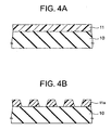
- an original disk comprised of a glass substrate 10 formed with a resist film 11 is prepared.
- a laser beam or electron beam etc. is used to expose the resist film 11 by a pattern exposing for example the regions for forming the trenches of the disk substrate, then this is developed to form a resist film 11a of a pattern open at regions for forming the trenches of the disk substrate.
- the resist film 11a is patterned to finally obtain a pattern where wobble W is formed in the side wall portions at the inner circumferential side of the disk substrate when seen from the grooves G and at the outer circumferential side of the disk substrate when seen from the lands L as described above in the structure of the optical disk.
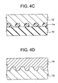
- a metal master 12 is formed on the resist film 11a on the glass substrate 10.
- the surface of the metal master 12 has transferred to it the relief of a reverse pattern to the relief of the pattern formed by the glass substrate 10 and the resist film 11a.
- the mother 13 is formed on the metal master 12.
- the surface of the mother 13 has transferred to it the relief of a reverse pattern to the relief of the surface of the metal master 12.
- the metal master 12 is drawn arranged at the bottom and turned upside down with respect to FIG. 4C.
- the stamper 14 is formed on the mother 13.
- the surface of the stamper 14 has transferred to it the relief of a reverse pattern to the relief of the surface of the mother 13.
- the mother 13 is drawn arranged at the bottom and turned upside down with respect to FIG. 4D.
- FIG. 4F for example, compression molding, injection molding, 2P (photo polymerization), etc. is used to form on the relief pattern of the stamper 14 a polycarbonate or other plastic substrate, that is, the disk substrate 15.
- the disk substrate 15 has transferred to it trenches 15a forming relief of a reverse pattern to the relief of the surface of the stamper 14.
- the stamper 14 is drawn arranged at the bottom and turned upside down with respect to FIG. 4E.
- a disk substrate having trenches of a pattern same to the pattern of the openings formed by the resist film 11a formed at the step shown in FIG. 4B, that is, trenches of a pattern where wobble W is formed in the side wall portions at the inner circumferential side of the disk substrate when seen from the grooves G and at the outer circumferential side of the disk substrate when seen from the lands L can be formed.
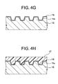
- an optical recording layer 16 having a laminate of for example a dielectric film, a recording layer, another dielectric film, and a reflection film in that film formation order.
- the protection layer 17 is formed above the optical recording layer 16.
- an optical disk of the structure shown in FIG. 2A, FIG. 2B, FIG. 3A, and FIG. 3B can be produced.
- the wobble W for providing the clock information or address information is formed in the side wall portions at the inner circumferential side of the disk substrate when seen from the grooves G and at the outer circumferential side of the disk substrate when seen from the lands L among the pairs of facing side walls forming the trenches 15a.
- FIG. 5 is a schematic view of the configuration of an example of an exposure apparatus (cutting machine) used in the exposure step of the resist film shown in FIG. 4B described above.
- a laser beam LB emitted from a laser beam source 30 such as an He-Cd laser is split into a first laser beam LB1 and a second laser beam LB2 by a half mirror 31a.
- the first laser beam LB1 passing through the half mirror 31a strikes a beam combiner 33 via a mirror 31b and a mirror 31c.
- the second laser beam LB2 reflected at the half mirror 31a strikes the beam combiner 33 via a mirror 31d, optical acoustic element 32, and mirror 31e.
- the first laser beam LB1 and the second laser beam LB2 are combined at the beam combiner 33, reflected at a mirror 31f, guided to an original disk 34 comprised of a glass substrate 10 formed with a resist film 11, and used for exposure.
- the optical acoustic element 32 can perform control to shake an optical axis of the second laser beam LB2 by a fine angle.
- FIG. 6A is a schematic view of the state when performing the exposure processing by the first laser beam LB1 and the second laser beam LB2.
- the resist film is exposed so as to finally exhibit a pattern wherein the wobble W is formed in the side wall portion at the inner circumferential side of the disk substrate when seen from the groove G and at the outer circumferential side of the disk substrate when seen from the land L in the structure of the optical disk at the interface between the region R G for forming the groove and the region R L for forming the land.
- the first laser beam LB1 is swept over the film without shaking so that the endmost portion of the spot of the first laser beam LB1 forms the interface between the region R G for forming the groove and the region R L for forming the land at the side where the wobble is not to be formed, while the second laser beam LB2 is modulated by the optical acoustic element arranged on the optical axis of the second laser beam of the exposure apparatus shown in FIG. 5 and swept while slightly shaking in a direction perpendicular to the advance direction so that the endmost portion of the spot of the second laser beam LB2 forms the interface between the region R G for forming the groove and the region R L for forming the land at the side where the wobble is to be formed.
- FIG. 6B shows the light intensity profile of the first laser beam LB1 and the laser beam LB2 described above, wherein an ordinate shows the light intensity, and an abscissa shows the location.
- the second laser beam LB2 is modulated and given coma aberration due to its being inclined more than the first laser beam LB1 and aberration of the optical acoustic element due to its passing through the element, so the beam profile has a broader width than the first laser beam LB1.
- the second laser beam LB2 has a profile having a broader width than the first laser beam LB1 as described above, as shown in FIG. 6C, at the sectional pattern of the resist film 11a formed by the exposure and development, the inclination of the wall surface of the resist film 11a corresponding to the interface between the region R G for forming the groove and the region R L for forming the land formed by tracing by the endmost portion of each beam becomes gentler at the side traced by the second laser beam LB2 where the wobble W is formed than the side traced by the first laser beam LB1 where the wobble is not formed.
- FIG. 7A is a schematic view of the configuration of a sputtering apparatus used in the film formation step of the optical recording layer.
- the disk substrate 15 faces a target T with its trench forming surface up.
- Sputtering particles flying out of the target in the sputtering step are deposited on the trench forming surface of the disk substrate 15.
- the sputter particles from the entire surface of the target T are deposited, so due to the sputter particle component mainly obliquely striking the disk substrate 15, as shown in FIG. 7B, corresponding to an enlarged view of the Y 2 portion in FIG. 7A, the inner circumferential side of the recess (groove G) of the relief of the trench 15a falls in the shadow of the projection (land L) and therefore the thickness of the formed optical recording layer 16 becomes thinner, that is, unevenness of the film formation occurs.
- the thickness of the optical recording layer 16 becomes smaller at the inner circumferential side of the recess (groove G) and at the outer circumferential side of the projection (land L) in the relief of the trench 15a of the disk substrate 15, while conversely the thickness of the optical recording layer 16 becomes greater at the outer circumferential side of the recess (groove G) and at the inner circumferential side of the projection (land L).
- the sputter particles are deposited equally from all directions, so a uniform film thickness is obtained, but usually the disk center becomes an opening region, so can not be used.
- FIG. 7C shows the jitter with respect to the write power.
- a solid line “a” shows the case of cross write from the land L on the outer circumferential side to the groove G on the inner circumferential side
- a broken line “b” shows the case of cross write from the land L on the inner circumferential side to the groove G on the outer circumferential side.
- the optical recording layer is thick from the land L on the outer circumferential side to the groove G on the inner circumferential side, so the write power region (margin) able to suppress the jitter is relatively narrow.
- the optical recording layer is thin from the land L on the inner circumferential side to the groove G on the outer circumferential side, so the write power region (margin) able to suppress the jitter is relatively wide.
- the optical recording layer becomes thinner at the inner circumferential side of the recess (groove G) of the relief of the trench 15a of the disk substrate 15 and becomes thicker at the outer circumferential side of the recess (groove G) as described above, if the wobble were provided at the outer circumferential side of the recess (groove G), the film would become further thicker and the write power margin of the cross write from the land L at the outer circumferential side to the groove G at the inner circumferential side would become increasingly narrower.
- the optical recording layer at the inner circumferential side of the recess becomes thicker, but this only makes the margin of the cross write from the land L at the inner circumferential side to the groove G at the outer circumferential side narrower, where the write power margin was originally wide, therefore does not make the write power margin of the overall optical disk any narrower.
- the wobble is provided at the inner circumferential side when seen from the recess (groove) of the disk substrate and at the outer circumferential side when seen from the projection (land), the increase of the problem of cross write can be suppressed and the wobble is desirably arranged for the production process.
- FIG. 8A is a schematic sectional view showing a step of forming on the relief pattern of the stamper 14 a polycarbonate or other plastic substrate, that is, the disk substrate 15.
- FIG. 8B corresponds to an enlarged view of the Y 3 portion in FIG. 8A when separating the disk substrate 15 from the stamper 14 in the above step.
- a stamper 14 which is generally made of metal
- a disk substrate 15 made of polycarbonate or another plastic
- the plastic forming the disk substrate 15 has a larger linear expansion coefficient than the metal forming the stamper 14, the amount of shrinkage to the inner side of the diameter becomes larger than that of the stamper.
- the disk substrate 15 is separated from the stamper 14 while the inner circumferential sides of the projections (lands L) of the disk substrate 15 are caught by the projections of the stamper.
- the final contact area becomes small, considerable stress is applied to angle portions Z at the inner circumferential side wall surfaces of the lands L, so a dragging angle accompanied by deformation is generated.
- the inner circumferential side wall surfaces of the lands L are apt to be damaged for the above reason. If wobble were provided there, there would be a possibility of a drop in the quality of the wobble signal.
- the wobble is desirably arranged for the production process.
- the side wall portions at the inner circumferential side of the disk substrate when seen from the recesses (grooves) and at the outer circumferential side of the disk substrate when seen from the projections (lands) are not easily damaged at the time of formation of the disk substrate, so if the wobble is provided there, a drop in the quality of the wobble signal can be prevented, the increase of the problem of cross write can be suppressed, and, in an optical recording medium of the land-groove recording format etc. having wobble at part of the interfaces of lands and grooves, the wobble is desirably arranged for the production process.
- An optical disk according to the present embodiment in the same way as the first embodiment shown in FIG. 2, has a laminate of a disk substrate, optical recording layer, and protection layer and has an approximately disk shape having an opening portion at the center.
- FIG. 9A is a sectional view of the optical disk according to the present embodiment.
- a disk substrate 15 having a thickness D1 of 1.1 to 1.2 mm is alternately provided on one surface with a first trench 15a 1 and a second trench 15a 2 deeper than the first trench 15a 1 .
- An optical recording layer 16 comprised of for example a dielectric film, a recording film, another dielectric film, and a reflection film stacked in that order is formed on that surface.
- the film configuration and number of layers differ according to the type of the recording material and the design.
- the protection layer 17 is formed above the optical recording layer 16.
- the optical recording layer 16 has relief shapes corresponding to the first trenches 15a 1 and the second trenches 15a 2 .
- the track regions are divided into regions projecting out to the protection layer 17 side when seen from the disk substrate 15, that is, the lands L, and recessed region in the first trenches 15a 1 , that is, first grooves G1, and recessed regions in the second trenches 15a 2 , that is, second grooves G2.
- the widths of the flat portions of the lands L, first grooves G1, and second grooves G2 are formed approximately equally.
- either of for example the lands L and the grooves are used as the recording regions. It is also possible to use both regions as the recording regions.
- the optical limit is extended by doubling the cycle of generation of the tracking error signal in length. It is therefore possible to increase the recording density.
- FIG. 9B is a plan view of the optical disk showing the shape and arrangement of the trenches for dividing the lands L and the grooves (first grooves G1 and second grooves G2) in the above optical disk and corresponds to a top view of the optical disk of the sectional view shown in FIG. 9A.
- the wobble W for providing the clock information or address information is formed at the side wall portions of the grooves on the shallower side between the two types of grooves differing in depth (first grooves G1 and second grooves G2), that is, the first grooves G1.
- the optical disk of the present embodiment in the same way as the optical disk according to the first embodiment, can be recorded on or reproduced from by an optical disk device having the usual configuration.
- the return light reflected at the optical recording layer is received at a light receiving element, and a predetermined matrix circuit or the like detects, for example, a focus error signal by the astigmatism method, a tracking error signal by the differential push pull method, or other servo error signal, an RF signal, or a wobble signal for performing the detection of a clock signal synchronized with the disk rotation and addresses etc.
- the optical disk of the present embodiment described above is an optical disk of the depth modulation recording format. It is explained that the above arrangement of wobble is preferred for reasons of the production process.
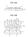
- FIG. 10A is a schematic sectional view showing the step of forming on the relief pattern of a stamper 14 a polycarbonate or other plastic substrate, that is, the disk substrate 15, while FIG. 10B corresponds to an enlarged view of the Y 4 portion in FIG. 10A when separating the disk substrate 15 from the stamper 14 in the above step.
- the stamper 14 which is generally made of metal
- a disk substrate 15 made of polycarbonate or another plastic since the plastic forming the disk substrate 15 has a larger linear expansion coefficient than the metal forming the stamper 14, the amount of shrinkage to the inner side of the diameter becomes larger than that of the stamper.
- the disk substrate is separated from the stamper 14 while the inner circumferential sides of the lands L on the sides facing the deeper second grooves G2 are caught by the projections of the stamper.
- the final contact area becomes smaller, a considerable stress is applied to the angle portions Z of the inner circumferential side wall surfaces facing the second grooves G2, so a dragging angle accompanied by deformation is generated.
- the wall surfaces of the trenches facing the deeper second grooves G2 are apt to be damaged for the above reasons. If the wobble were provided there, there would be a possibility of a drop in the quality of the wobble signal.
- the wall surfaces of the shallower trenches are not damaged at the time of mold separation, so if the wobble is provided there, a drop in the quality of the wobble signal can be prevented.
- the damage at the time of mold separation described above becomes conspicuous when the grooves are deep, for example, about 100 nm or more. In such a case, the effect of arranging the wobble as described above becomes large.
- the optical disk according to the present embodiment has a plurality of types of trenches differing in depth for dividing the track regions into lands and the grooves.
- the side wall surfaces of the shallower trenches are not apt to be damaged at the time of formation of the disk substrate, so if providing the wobble there, a drop in the quality of the wobble signal can be prevented, and, in an optical recording medium of the depth modulation recording format etc. having the wobble in part of the interfaces between the lands and the grooves, the wobble is desirably arranged for the production process.
- the present invention is not limited to the above embodiments.
- the layer configuration of the optical recording layer is not limited to the configuration explained in the embodiments.
- Various structures can be employed in accordance with the material etc. of the recording film.
- the present invention can be applied to a magneto-optic recording medium or an optical disk medium using an organic pigment materials.
- a plurality of intermediate members such as a metal master and mother are formed, but it is also possible to use just one intermediate member or possible to use two or more intermediate members other than those explained in the above embodiments.
- optical recording medium of the present invention it is possible to provide an optical recording medium of the land-groove recording format, depth modulation recording format, etc. having wobble in part of the interfaces of the lands and the grooves, where the wobble is desirably arranged for the production process.
Landscapes
- Engineering & Computer Science (AREA)
- Manufacturing & Machinery (AREA)
- Optical Recording Or Reproduction (AREA)
- Optical Record Carriers And Manufacture Thereof (AREA)
Abstract
An optical recording medium having a wobble
desirably arranged in a production process when having
wobble at part of interfaces of lands and grooves is
provided. An optical recording medium comprising an
approximately disk-shaped disk substrate 15, formed in
its surface with trenches 15a and having projections and
recesses divided for every track region by the trenches
15a, on which are stacked an optical recording layer 16
having relief shapes corresponding with the trenches 15a
and a protection film 17 and of a format where both
regions of the projections (lands L) and the recesses
(grooves G) are used as recording regions etc., wherein
wobble W for providing clock information or address
information is formed, between a pair of facing side
walls forming each trench 15a, in a side wall portion at
an inner circumferential side of the disk substrate 15
when seen from the recess (groove G) and at an outer
circumferential side of the disk substrate 15 when seen
from the projection (land L).
Description
The present invention relates to an optical
recording medium (hereinafter also referred to as an
"optical disk"), more particularly relates to an optical
recording medium capable of high density recording.
In recent years, along with the development of
technology for digitally recording moving pictures, still
pictures, and other video data, large volumes of data are
now being handled. CD or DVD and other optical disk
devices are now in the limelight as large volume
recording devices. Research for further increasing
capacity is also underway.
FIG. 1 is a sectional view of a conventional optical
disk.
A protection layer 17 is formed above the optical
recording layer 16.
When recording on or reproducing from the optical
disk, a laser beam of a predetermined wavelength or other
light is focused on the optical recording layer 16 from
the disk substrate 15 side.
When reproducing from the optical disk, return light
reflected at the optical recording layer 16 is received
by a light receiving element, a predetermined signal is
generated by a signal processing circuit, and a
reproduction signal is extracted.
In the optical disk as described above, the optical
recording layer 16 also has relief shapes corresponding
to the trenches 15a provided in the surface of the disk
substrate 15. These trenches 15a divide the track regions.
Below, regions projecting outward to the protection
layer 17 side when seen from the disk substrate 15 will
be referred to as "lands L", while recessed regions will
be referred to as "grooves G".
In accordance with the design of the optical disk,
one or both of the above divided lands L and grooves G
are selected as the recording regions.
FIG. 1A is a sectional view of an optical disk of a
format wherein for example only the land L regions are
used as the recording regions, and the groove G regions
are provided as regions for dividing the track regions.
Further, in other optical disks, there is also a
format wherein only the groove G regions are used as the
recording regions, and the land L regions are provided as
regions for dividing the track regions.
Further, in order to improve the surface recording
density, a land-groove recording format using both the
regions of the lands L and grooves G as recording regions
etc. has been developed.
This deals with the servo signal attenuation due to
the optical MTF (modulation transfer function) hindering
higher density in the track direction by using both of
the lands L and the grooves G so as to obtain double the
recording tracks of the cycle of generation of the
tracking error signal, that is, the group pitch, and thus
increase the recording density.
Further, a depth modulation recording format
alternately arranges grooves having different depths to
double the length of the cycle of generation of the
tracking error signal so as to extend the optical limit
and thus increase the recording density.
On the other hand, it is possible to make the inner
surface forming the trench 15a formed in the disk
substrate 15 meander, that is, form a so-called "wobble".
For example, in one format of a MD (Minidisc), as
shown in FIG. 1B, only the land L regions are used as the
recording regions, the groove G regions are provided as
regions for dividing the track regions, and grooves G
formed with wobbles W and grooves G not formed with
wobbles W and having inner surfaces extending linearly
are alternately arranged.
From the above wobble W, a predetermined wobble
matrix circuit or the like detects address information of
the tracks, a clock for controlling the rotational speed
of the disk, and the like. When recording address
information or the like in the wobble, address
information becomes unnecessary at the optical recording
layer in the lands and grooves, so the recording density
can be improved by that amount.
It is also possible to apply the wobble to the land-groove
recording format and depth modulation recording
format.
However, in order to prevent interference of
adjacent track information due to optical MTF, it can be
considered to form the wobble on one side of the wall
surfaces of land-groove interfaces in the land-groove
recording format or to arrange grooves having wobbles at
a predetermined cycle similar to the cycle of the depth
of grooves in the depth modulation recording format, but
there is nothing prescribing the arrangement of wobbles.
No optical disks having wobbles arranged desirably for
the production process such as the mastering step,
molding step, and a film formation step has yet been
known.
The present invention was made in consideration with
the above circumstance. Accordingly, an object of the
present invention is to provide an optical recording
medium of the land-groove recording format, the depth
modulation recording format, etc. having wobble arranged
at part of the interface of the lands and the grooves,
wherein the wobbles are arranged in a desired fashion for
the production process.
To achieve the above object, the optical recording
medium of the present invention comprises an
approximately disk-shaped disk substrate formed with
trenches in a surface thereof and having projections and
recesses divided for every track region by the trenches,
an optical recording layer formed on the disk substrate
on the trench forming surface and having relief shapes
corresponding to the trenches, and a protection film
formed on the optical recording layer, wherein wobble is
formed, between a pair of facing side walls forming each
trench, in a side wall portion at an inner
circumferential side of the disk substrate when seen from
the recess and at an outer circumferential side of the
disk substrate when seen from the projection.
In the above optical recording medium of the present
invention, preferably the wobble provides at least clock
information or address information.
In the above optical recording medium of the present
invention, preferably both of the projections and the
recesses divided for every track region on the optical
recording layer are used as recording regions.
In the above optical recording medium of the present
invention, preferably the disk substrate is a plastic
substrate to which a relief pattern is transferred from a
stamper having relief of a reverse pattern to the pattern
of projections and the recesses divided by the trenches.
In the above optical recording medium of the present
invention, on an approximately disk-shaped disk substrate,
formed with trenches in its surface and having
projections and recesses divided for every track region
by the trenches, are stacked an optical recording layer
having relief shapes corresponding to the trenches and a
protection film. In the optical recording medium of a
format where both regions of the projections (lands) and
recesses (grooves) are used as recording regions, etc.
wobble for providing clock information or address
information is formed, between a pair of facing side
walls forming each trench, in a side wall portion at the
inner circumferential side of the disk substrate when
seen from the recess (groove) and at the outer
circumferential side of the disk substrate when seen from
the projection (land).
In an optical recording medium of the land-groove
recording format etc., at the time of molding the disk
substrate to which the relief pattern is transferred from
a stamper having relief of a reverse pattern to the
pattern of projections and recesses divided by the
trenches, the side wall portions at the outer
circumferential side of the disk substrate when seen from
the recesses (grooves) and at the inner circumferential
side of the disk substrate when seen from the projections
(lands) are easily damaged, so if wobble were provided
there, the quality of the wobble signal might end up
dropping. Also, if wobble were provided in the above
portions, the problem of cross write, that is, the signal
of a groove being erased when writing at a land or
conversely the signal of a land being erased when writing
at a groove, would increase.
On the other hand, the side wall portions at the
inner circumferential side of the disk substrate when
seen from the recesses (grooves) and at the outer
circumferential side of the disk substrate when seen from
the projections (lands) are not easily damaged, so if
wobble is provided there, a drop in quality of the wobble
signal can be prevented and an increase of the problem of
cross write can be suppressed.
Namely, there is provided an optical recording
medium of the land-groove recording format etc. having
wobble at part of the interfaces of lands and grooves,
wherein the wobble is desirably arranged for the
production process.
Further, to attain the above object, the optical
recording medium of the present invention comprises an
approximately disk-shaped disk substrate formed in a
surface thereof with a plurality of types of trenches
differing in depth and having projections and recesses
divided for every track region by the trenches, an
optical recording layer formed on the disk substrate on
the trench forming surface and having relief shapes
corresponding to the trenches, and a protection film
formed on the optical recording layer, wherein wobble is
formed in side wall portions of shallower trenches among
the plurality of types of trenches differing in depth.
In the above optical recording medium of the present
invention, preferably the disk substrate is formed with,
as the trenches, first trenches of a first depth and
second trenches of a second depth deeper than the first
depth and the wobble is formed in the side wall portions
of the first trenches.
In the above optical recording medium of the present
invention, preferably the wobble provides at least clock
information or address information.
In the above optical recording medium of the present
invention, preferably one of the projections and the
recesses divided for every track region on the optical
recording layer is used as a recording region.
In the above optical recording medium of the present
invention, preferably the disk substrate is a plastic
substrate to which a relief pattern is transferred from a
stamper having relief of a reverse pattern to the pattern
of projections and recesses divided by the trenches.
In the above optical recording medium of the present
invention, on an approximately disk-shaped disk substrate,
formed in its surface with a plurality of types of
trenches differing in depth and having projections and
recesses divided for every track region by the trenches,
are stacked an optical recording layer having relief
shapes corresponding to the trenches and a protection
film. In the optical recording medium of a format where
one region of the projections (lands) or recesses
(grooves) is used as the recording region, etc., wobble
is formed in the side wall portions of shallower trenches
among the plurality of types of trenches differing in
depth.
For example, as the trenches provided in the disk
substrate, first trenches of a first depth and second
trenches of a second depth deeper than the first depth
are formed, and wobble is formed in the side wall
portions of the first trenches.
In the optical recording medium of the depth
modulation recording format etc., at the time of molding
the disk substrate to which the relief pattern is
transferred from a stamper having relief a reverse
pattern to the pattern of the projections and recesses
divided by the trenches, the side wall portions of the
deeper trenches are easily damaged, so if the wobble were
provided there, the quality of the wobble signal might
end up dropping.
On the other hand, the side wall portions of the
shallower trenches are not easily damaged at the time of
molding the disk substrate, so if the wobble is provided
there, a drop in the quality of the wobble signal can be
prevented.
Namely, there is provided an optical recording
medium of the depth modulation recording format etc.
having wobble at part of the interfaces of lands and
grooves, wherein the wobble is desirably arranged for the
production process.
Below, a detailed explanation will be given of
embodiments of the present invention by using the
drawings.
FIG. 2A is a perspective view of an optical disk
according to the present embodiment, while FIG. 2B is a
sectional view along X-X' in FIG. 2A.
An optical disk 1 has a laminate of a disk substrate
15, optical recording layer 16, and protection layer 17
and has an approximately disk shape having an opening at
its center.
FIG. 3A is a schematic view showing a sectional
structure corresponding to an enlarged view of the Y1
portion in FIG. 2B and a method of focusing light. In the
figure, the right side is the inner circumferential side
of the disk, and the left side is the outer
circumferential side.
The protection layer 17 is formed above the optical
recording layer 16.
In the above optical disk, the optical recording
layer 16 is formed with relief shapes corresponding to
the trenches 15a. The track regions are divided into
regions projecting outward to the protection layer 17
side when seen from the disk substrate 15, that is, lands
L, and recessed regions, that is, grooves G.
In the present embodiment, for example both the
regions of the lands L and the grooves G are used as
recording regions.
FIG. 3B is a plan view of the optical disk showing
the shape and arrangement of the trenches 15a dividing
the lands L and grooves G in the above optical disk and
corresponds to a top view of the optical disk of the
sectional view shown in FIG. 3A. In the figure, the right
side is the inner circumferential side of the disk, and
the left side is the outer circumferential side.
Among the pair of facing side walls forming each
trench 15a, the wobble W for providing the clock
information or address information is formed in the side
wall portion at the inner circumferential side of the
disk substrate when seen from the groove G and at the
outer circumferential side of the disk substrate when
seen from the land L.
The optical disk of the present embodiment can be
recorded on or reproduced from by an optical disk drive
having a usual configuration. At the time of recording or
reproduction, as shown in FIG. 3A, a laser beam LB for
reproduction or recording is focused by an object lens OL
or the like, passes through the light transmission type
disk substrate 15, and strikes the optical recording
layer 16 of the optical disk of the above structure.
At the time of reproduction, the return light
reflected at the optical recording layer is received at a
light receiving element, a predetermined signal is
generated by the signal processing circuit, and the
reproduction signal is extracted.
Namely, from the received signal obtained by
receiving the reflected beam, various predetermined
matrix circuits or the like detect, for example, a focus
error signal by the astigmatism method, a tracking error
signal by the differential push pull method or other
servo error signal, an RF signal, or a wobble signal for
performing the detection of a clock signal synchronized
with the disk rotation and addresses etc.
An explanation will be given next of the method for
production of the optical disk of the present embodiment.
First, as shown in FIG. 4A, an original disk
comprised of a glass substrate 10 formed with a resist
film 11 is prepared.
Next, as shown in FIG. 4B, a laser beam or electron
beam etc. is used to expose the resist film 11 by a
pattern exposing for example the regions for forming the
trenches of the disk substrate, then this is developed to
form a resist film 11a of a pattern open at regions for
forming the trenches of the disk substrate.
In this exposure step, the resist film 11a is
patterned to finally obtain a pattern where wobble W is
formed in the side wall portions at the inner
circumferential side of the disk substrate when seen from
the grooves G and at the outer circumferential side of
the disk substrate when seen from the lands L as
described above in the structure of the optical disk.
Next, as shown in FIG. 4C, for example silver
plating or other film forming processing is used to form
a metal master 12 on the resist film 11a on the glass
substrate 10. The surface of the metal master 12 has
transferred to it the relief of a reverse pattern to the
relief of the pattern formed by the glass substrate 10
and the resist film 11a.
Next, as shown in FIG. 4D, the mother 13 is formed
on the metal master 12. The surface of the mother 13 has
transferred to it the relief of a reverse pattern to the
relief of the surface of the metal master 12. In the
figure, the metal master 12 is drawn arranged at the
bottom and turned upside down with respect to FIG. 4C.
Next, as shown in FIG. 4E, the stamper 14 is formed
on the mother 13. The surface of the stamper 14 has
transferred to it the relief of a reverse pattern to the
relief of the surface of the mother 13. In the figure,
the mother 13 is drawn arranged at the bottom and turned
upside down with respect to FIG. 4D.
Next, as shown in FIG. 4F, for example, compression
molding, injection molding, 2P (photo polymerization),
etc. is used to form on the relief pattern of the stamper
14 a polycarbonate or other plastic substrate, that is,
the disk substrate 15. The disk substrate 15 has
transferred to it trenches 15a forming relief of a
reverse pattern to the relief of the surface of the
stamper 14. In the figure, the stamper 14 is drawn
arranged at the bottom and turned upside down with
respect to FIG. 4E.
By the above steps, a disk substrate having trenches
of a pattern same to the pattern of the openings formed
by the resist film 11a formed at the step shown in FIG.
4B, that is, trenches of a pattern where wobble W is
formed in the side wall portions at the inner
circumferential side of the disk substrate when seen from
the grooves G and at the outer circumferential side of
the disk substrate when seen from the lands L can be
formed.
Next, as shown in FIG. 4G, for example sputtering is
used to form an optical recording layer 16 having a
laminate of for example a dielectric film, a recording
layer, another dielectric film, and a reflection film in
that film formation order.
Next, as shown in FIG. 4H, the protection layer 17
is formed above the optical recording layer 16.
By the above, an optical disk of the structure shown
in FIG. 2A, FIG. 2B, FIG. 3A, and FIG. 3B can be produced.
In the above optical disk, the wobble W for
providing the clock information or address information is
formed in the side wall portions at the inner
circumferential side of the disk substrate when seen from
the grooves G and at the outer circumferential side of
the disk substrate when seen from the lands L among the
pairs of facing side walls forming the trenches 15a.
By this, an optical disk where a drop in quality of
the wobble signal can be prevented, an increase of the
problem of cross write can be suppressed, and the wobble
is desirably arranged for the production process is
achieved. The reasons for this will be explained below.
FIG. 5 is a schematic view of the configuration of
an example of an exposure apparatus (cutting machine)
used in the exposure step of the resist film shown in FIG.
4B described above.
A laser beam LB emitted from a laser beam source 30
such as an He-Cd laser is split into a first laser beam
LB1 and a second laser beam LB2 by a half mirror 31a.
The first laser beam LB1 passing through the half
mirror 31a strikes a beam combiner 33 via a mirror 31b
and a mirror 31c.
On the other hand, the second laser beam LB2
reflected at the half mirror 31a strikes the beam
combiner 33 via a mirror 31d, optical acoustic element 32,
and mirror 31e.
The first laser beam LB1 and the second laser beam
LB2 are combined at the beam combiner 33, reflected at a
mirror 31f, guided to an original disk 34 comprised of a
glass substrate 10 formed with a resist film 11, and used
for exposure.
In the above configuration, the optical acoustic
element 32 can perform control to shake an optical axis
of the second laser beam LB2 by a fine angle.
FIG. 6A is a schematic view of the state when
performing the exposure processing by the first laser
beam LB1 and the second laser beam LB2.
By superimposing the first laser beam LB1 and the
second laser beam LB2, a region RG for forming a groove
on the resist film is exposed, while a region RL for
forming a land is prevented from being irradiated by the
laser beams.
At this time, the resist film is exposed so as to
finally exhibit a pattern wherein the wobble W is formed
in the side wall portion at the inner circumferential
side of the disk substrate when seen from the groove G
and at the outer circumferential side of the disk
substrate when seen from the land L in the structure of
the optical disk at the interface between the region RG
for forming the groove and the region RL for forming the
land.
Namely, the first laser beam LB1 is swept over the
film without shaking so that the endmost portion of the
spot of the first laser beam LB1 forms the interface
between the region RG for forming the groove and the
region RL for forming the land at the side where the
wobble is not to be formed, while the second laser beam
LB2 is modulated by the optical acoustic element arranged
on the optical axis of the second laser beam of the
exposure apparatus shown in FIG. 5 and swept while
slightly shaking in a direction perpendicular to the
advance direction so that the endmost portion of the spot
of the second laser beam LB2 forms the interface between
the region RG for forming the groove and the region RL
for forming the land at the side where the wobble is to
be formed.
By developing the resist film exposed in this way, a
resist film of a pattern having wobble as described above
can be formed.
FIG. 6B shows the light intensity profile of the
first laser beam LB1 and the laser beam LB2 described
above, wherein an ordinate shows the light intensity, and
an abscissa shows the location.
The second laser beam LB2 is modulated and given
coma aberration due to its being inclined more than the
first laser beam LB1 and aberration of the optical
acoustic element due to its passing through the element,
so the beam profile has a broader width than the first
laser beam LB1.
Due to the fact that the second laser beam LB2 has a
profile having a broader width than the first laser beam
LB1 as described above, as shown in FIG. 6C, at the
sectional pattern of the resist film 11a formed by the
exposure and development, the inclination of the wall
surface of the resist film 11a corresponding to the
interface between the region RG for forming the groove
and the region RL for forming the land formed by tracing
by the endmost portion of each beam becomes gentler at
the side traced by the second laser beam LB2 where the
wobble W is formed than the side traced by the first
laser beam LB1 where the wobble is not formed.
As a result of this, in the trench 15a of the disk
substrate 15 obtained from the above original disc, as
shown in FIG. 6D, in the wall surfaces of the trench 15a
forming the interface between the land L and the groove G,
the side where the wobble W was formed becomes the
gentler slope.
Considering the situation that the wall surface on
the side where the wobble W was formed becomes a gentler
slope in the trench 15a of the disk substrate 15, when
considering the film formation step of the optical
recording layer, it can be explained that the formation
of the wobble W in the side wall portion at the inner
circumferential side of the disk substrate when seen from
the groove G and at the outer circumferential side of the
disk substrate when seen from the land L becomes the
preferred arrangement for the following reason.
FIG. 7A is a schematic view of the configuration of
a sputtering apparatus used in the film formation step of
the optical recording layer.
The disk substrate 15 faces a target T with its
trench forming surface up.
Sputtering particles flying out of the target in the
sputtering step are deposited on the trench forming
surface of the disk substrate 15.
The sputter particles from the entire surface of the
target T are deposited, so due to the sputter particle
component mainly obliquely striking the disk substrate 15,
as shown in FIG. 7B, corresponding to an enlarged view of
the Y2 portion in FIG. 7A, the inner circumferential side
of the recess (groove G) of the relief of the trench 15a
falls in the shadow of the projection (land L) and
therefore the thickness of the formed optical recording
layer 16 becomes thinner, that is, unevenness of the film
formation occurs.
Namely, the thickness of the optical recording layer
16 becomes smaller at the inner circumferential side of
the recess (groove G) and at the outer circumferential
side of the projection (land L) in the relief of the
trench 15a of the disk substrate 15, while conversely the
thickness of the optical recording layer 16 becomes
greater at the outer circumferential side of the recess
(groove G) and at the inner circumferential side of the
projection (land L).
At the center of the disk substrate, the sputter
particles are deposited equally from all directions, so a
uniform film thickness is obtained, but usually the disk
center becomes an opening region, so can not be used.
When nonuniformity occurs in the film thickness of
the optical recording layer 16 as described above,
anisotropy occurs in the cross write where other data is
erased when writing on a land or groove. Namely, the
energy transfer is large in the portion where the film
thickness is great, so cross write via this thick portion
is apt to occur. Accordingly, the margin of the write
power for preventing cross write becomes narrow.
For example, FIG. 7C shows the jitter with respect
to the write power. A solid line "a" shows the case of
cross write from the land L on the outer circumferential
side to the groove G on the inner circumferential side,
while a broken line "b" shows the case of cross write
from the land L on the inner circumferential side to the
groove G on the outer circumferential side.
The optical recording layer is thick from the land L
on the outer circumferential side to the groove G on the
inner circumferential side, so the write power region
(margin) able to suppress the jitter is relatively narrow.
On the other hand, the optical recording layer is thin
from the land L on the inner circumferential side to the
groove G on the outer circumferential side, so the write
power region (margin) able to suppress the jitter is
relatively wide.
In relation to the cross write described above, when
considering the fact that the inclination of the wall
surface of the trench due to the wobble becomes gentler
as described above, the optical recording layer ends up
becoming thicker at the wall surface made gentler in
inclination due to the formation of the wobble, therefore
cross write is apt to occur.
Since the optical recording layer becomes thinner at
the inner circumferential side of the recess (groove G)
of the relief of the trench 15a of the disk substrate 15
and becomes thicker at the outer circumferential side of
the recess (groove G) as described above, if the wobble
were provided at the outer circumferential side of the
recess (groove G), the film would become further thicker
and the write power margin of the cross write from the
land L at the outer circumferential side to the groove G
at the inner circumferential side would become
increasingly narrower.
Conversely, if the wobble is provided at the inner
circumferential side of the recess (groove G), the
optical recording layer at the inner circumferential side
of the recess (groove G) becomes thicker, but this only
makes the margin of the cross write from the land L at
the inner circumferential side to the groove G at the
outer circumferential side narrower, where the write
power margin was originally wide, therefore does not make
the write power margin of the overall optical disk any
narrower.
Namely, it is explained that if the wobble is
provided at the inner circumferential side when seen from
the recess (groove) of the disk substrate and at the
outer circumferential side when seen from the projection
(land), the increase of the problem of cross write can be
suppressed and the wobble is desirably arranged for the
production process.
Also, it is explained that the above arrangement of
the wobble is preferred for other reasons in the
production process.
FIG. 8A is a schematic sectional view showing a step
of forming on the relief pattern of the stamper 14 a
polycarbonate or other plastic substrate, that is, the
disk substrate 15. FIG. 8B corresponds to an enlarged
view of the Y3 portion in FIG. 8A when separating the
disk substrate 15 from the stamper 14 in the above step.
For example, if compression molding, injection
molding, 2P (photo polymerization), etc. is used to form
and cool on the relief pattern of a stamper 14, which is
generally made of metal, a disk substrate 15 made of
polycarbonate or another plastic, since the plastic
forming the disk substrate 15 has a larger linear
expansion coefficient than the metal forming the stamper
14, the amount of shrinkage to the inner side of the
diameter becomes larger than that of the stamper.
For this reason, at the time of mold separation, as
shown in FIG. 8B, the disk substrate 15 is separated from
the stamper 14 while the inner circumferential sides of
the projections (lands L) of the disk substrate 15 are
caught by the projections of the stamper. When the final
contact area becomes small, considerable stress is
applied to angle portions Z at the inner circumferential
side wall surfaces of the lands L, so a dragging angle
accompanied by deformation is generated.
Accordingly, the inner circumferential side wall
surfaces of the lands L are apt to be damaged for the
above reason. If wobble were provided there, there would
be a possibility of a drop in the quality of the wobble
signal.
Conversely, the outer circumferential side walls
surface of the lands L will not be damaged at the time of
mold separation. Therefore, if the wobble is provided
there, a drop in the quality of the wobble signal can be
prevented.
Namely, if wobble is provided at the inner
circumferential side when seen from the recesses (groove)
of the disk substrate and at the outer circumferential
side when seen from the projections (lands), a drop in
the quality of the wobble signal due to the damage at the
time of mold separation can be prevented. Therefore, it
is explained that the wobble is desirably arranged for
the production process.
As described above, in the optical disk according to
the present embodiment, the side wall portions at the
inner circumferential side of the disk substrate when
seen from the recesses (grooves) and at the outer
circumferential side of the disk substrate when seen from
the projections (lands) are not easily damaged at the
time of formation of the disk substrate, so if the wobble
is provided there, a drop in the quality of the wobble
signal can be prevented, the increase of the problem of
cross write can be suppressed, and, in an optical
recording medium of the land-groove recording format etc.
having wobble at part of the interfaces of lands and
grooves, the wobble is desirably arranged for the
production process.
An optical disk according to the present embodiment,
in the same way as the first embodiment shown in FIG. 2,
has a laminate of a disk substrate, optical recording
layer, and protection layer and has an approximately disk
shape having an opening portion at the center.
FIG. 9A is a sectional view of the optical disk
according to the present embodiment.
A disk substrate 15 having a thickness D1 of 1.1 to
1.2 mm is alternately provided on one surface with a
first trench 15a1 and a second trench 15a2 deeper than
the first trench 15a1. An optical recording layer 16
comprised of for example a dielectric film, a recording
film, another dielectric film, and a reflection film
stacked in that order is formed on that surface. The film
configuration and number of layers differ according to
the type of the recording material and the design.
The protection layer 17 is formed above the optical
recording layer 16.
In the above optical disk, the optical recording
layer 16 has relief shapes corresponding to the first
trenches 15a1 and the second trenches 15a2. The track
regions are divided into regions projecting out to the
protection layer 17 side when seen from the disk
substrate 15, that is, the lands L, and recessed region
in the first trenches 15a1, that is, first grooves G1,
and recessed regions in the second trenches 15a2, that is,
second grooves G2. The widths of the flat portions of the
lands L, first grooves G1, and second grooves G2 are
formed approximately equally.
In the present embodiment, either of for example the
lands L and the grooves (first grooves G1 and second
grooves G2) are used as the recording regions. It is also
possible to use both regions as the recording regions.
In a depth modulation recording format where grooves
differing in depth are alternately arranged as described
above, the optical limit is extended by doubling the
cycle of generation of the tracking error signal in
length. It is therefore possible to increase the
recording density.
FIG. 9B is a plan view of the optical disk showing
the shape and arrangement of the trenches for dividing
the lands L and the grooves (first grooves G1 and second
grooves G2) in the above optical disk and corresponds to
a top view of the optical disk of the sectional view
shown in FIG. 9A.
The wobble W for providing the clock information or
address information is formed at the side wall portions
of the grooves on the shallower side between the two
types of grooves differing in depth (first grooves G1 and
second grooves G2), that is, the first grooves G1.
The optical disk of the present embodiment, in the
same way as the optical disk according to the first
embodiment, can be recorded on or reproduced from by an
optical disk device having the usual configuration. At
the time of reproduction, the return light reflected at
the optical recording layer is received at a light
receiving element, and a predetermined matrix circuit or
the like detects, for example, a focus error signal by
the astigmatism method, a tracking error signal by the
differential push pull method, or other servo error
signal, an RF signal, or a wobble signal for performing
the detection of a clock signal synchronized with the
disk rotation and addresses etc.
The optical disk of the present embodiment described
above is an optical disk of the depth modulation
recording format. It is explained that the above
arrangement of wobble is preferred for reasons of the
production process.
FIG. 10A is a schematic sectional view showing the
step of forming on the relief pattern of a stamper 14 a
polycarbonate or other plastic substrate, that is, the
disk substrate 15, while FIG. 10B corresponds to an
enlarged view of the Y4 portion in FIG. 10A when
separating the disk substrate 15 from the stamper 14 in
the above step.
For example, if compression molding, injection
molding, 2P (photo polymerization), or the like is used
to form and cool on the relief pattern of the stamper 14,
which is generally made of metal, a disk substrate 15
made of polycarbonate or another plastic, since the
plastic forming the disk substrate 15 has a larger linear
expansion coefficient than the metal forming the stamper
14, the amount of shrinkage to the inner side of the
diameter becomes larger than that of the stamper.
For this reason, at the time of the mold separation,
as shown in FIG. 10B, the disk substrate is separated
from the stamper 14 while the inner circumferential sides
of the lands L on the sides facing the deeper second
grooves G2 are caught by the projections of the stamper.
When the final contact area becomes smaller, a
considerable stress is applied to the angle portions Z of
the inner circumferential side wall surfaces facing the
second grooves G2, so a dragging angle accompanied by
deformation is generated.
Accordingly, the wall surfaces of the trenches
facing the deeper second grooves G2 are apt to be damaged
for the above reasons. If the wobble were provided there,
there would be a possibility of a drop in the quality of
the wobble signal.
Conversely, the wall surfaces of the shallower
trenches are not damaged at the time of mold separation,
so if the wobble is provided there, a drop in the quality
of the wobble signal can be prevented.
The damage at the time of mold separation described
above becomes conspicuous when the grooves are deep, for
example, about 100 nm or more. In such a case, the effect
of arranging the wobble as described above becomes large.
As described above, the optical disk according to
the present embodiment has a plurality of types of
trenches differing in depth for dividing the track
regions into lands and the grooves. The side wall
surfaces of the shallower trenches are not apt to be
damaged at the time of formation of the disk substrate,
so if providing the wobble there, a drop in the quality
of the wobble signal can be prevented, and, in an optical
recording medium of the depth modulation recording format
etc. having the wobble in part of the interfaces between
the lands and the grooves, the wobble is desirably
arranged for the production process.
The present invention is not limited to the above
embodiments.
For example, the layer configuration of the optical
recording layer is not limited to the configuration
explained in the embodiments. Various structures can be
employed in accordance with the material etc. of the
recording film.
Further, other than a phase change type optical
recording medium, the present invention can be applied to
a magneto-optic recording medium or an optical disk
medium using an organic pigment materials.
Further, in order to produce the disk substrate, a
plurality of intermediate members such as a metal master
and mother are formed, but it is also possible to use
just one intermediate member or possible to use two or
more intermediate members other than those explained in
the above embodiments.
Other than this, various modifications can be made
within a range not out of the gist of the present
invention.
According to the optical recording medium of the
present invention, it is possible to provide an optical
recording medium of the land-groove recording format,
depth modulation recording format, etc. having wobble in
part of the interfaces of the lands and the grooves,
where the wobble is desirably arranged for the production
process.
Claims (9)
- An optical recording medium comprisingan approximately disk-shaped disk substrate formed with trenches in a surface thereof and having projections and recesses divided for every track region by the trenches,an optical recording layer formed on said disk substrate on said trench forming surface and having relief shapes corresponding to said trenches, anda protection film formed on said optical recording layer, whereinwobble is formed, between a pair of facing side walls forming each said trench, in a side wall portion at an inner circumferential side of said disk substrate when seen from said recess and at an outer circumferential side of the disk substrate when seen from said projection.
- An optical recording medium as set forth in claim 1, wherein said wobble provides at least clock information or address information.
- An optical recording medium as set forth in claim 1, wherein both of the projections and the recesses divided for every said track region on the optical recording layer are used as recording regions.
- An optical recording medium as set forth in claim 1, wherein said disk substrate is a plastic substrate to which a relief pattern is transferred from a stamper having relief of a reverse pattern to the pattern of projections and the recesses divided by said trenches.
- An optical recording medium comprisingan approximately disk-shaped disk substrate formed in a surface thereof with a plurality of types of trenches differing in depth and having projections and recesses divided for every track region by the trenches,an optical recording layer formed on said disk substrate on said trench forming surface and having relief shapes corresponding to the trenches, anda protection film formed on said optical recording layer, whereinwobble is formed in side wall portions of shallower trenches among said plurality of types of trenches differing in depth.
- An optical recording medium as set forth in claim 5, whereinsaid disk substrate is formed with, as said trenches, first trenches of a first depth and second trenches of a second depth deeper than the first depth andsaid wobble is formed in the side wall portions of said first trenches.
- An optical recording medium as set forth in claim 5, wherein said wobble provides at least clock information or address information.
- An optical recording medium as set forth in claim 5, wherein one of the projections and the recesses divided for every said track region on the optical recording layer is used as a recording region.
- An optical recording medium as set forth in claim 5, wherein said disk substrate is a plastic substrate to which a relief pattern is transferred from a stamper having relief of a reverse pattern to the pattern of projections and recesses divided by said trenches.
Applications Claiming Priority (3)
| Application Number | Priority Date | Filing Date | Title |
|---|---|---|---|
| JP2001001835 | 2001-01-09 | ||
| JP2001001835A JP2002208186A (en) | 2001-01-09 | 2001-01-09 | Optical recording medium |
| PCT/JP2002/000028 WO2002056308A1 (en) | 2001-01-09 | 2002-01-09 | Optical recording medium |
Publications (2)
| Publication Number | Publication Date |
|---|---|
| EP1267336A1 true EP1267336A1 (en) | 2002-12-18 |
| EP1267336A4 EP1267336A4 (en) | 2007-02-14 |
Family
ID=18870425
Family Applications (1)
| Application Number | Title | Priority Date | Filing Date |
|---|---|---|---|
| EP02729517A Withdrawn EP1267336A4 (en) | 2001-01-09 | 2002-01-09 | OPTICAL RECORDING MEDIUM |
Country Status (7)
| Country | Link |
|---|---|
| US (1) | US7038998B2 (en) |
| EP (1) | EP1267336A4 (en) |
| JP (1) | JP2002208186A (en) |
| KR (1) | KR20020079981A (en) |
| CN (1) | CN1455920A (en) |
| TW (1) | TW565834B (en) |
| WO (1) | WO2002056308A1 (en) |
Cited By (2)
| Publication number | Priority date | Publication date | Assignee | Title |
|---|---|---|---|---|
| WO2004072968A1 (en) | 2003-02-14 | 2004-08-26 | Sony Corporation | Optical recording medium, stamper for producing optical recording medium, recording/reproducing apparatus, and recording/reproducing method |
| EP1477973A3 (en) * | 2003-05-15 | 2007-11-14 | Sony Corporation | Optical recording medium, master for optical recording medium manufacture, recording and reproducing apparatus, and recording and reproducing method |
Families Citing this family (7)
| Publication number | Priority date | Publication date | Assignee | Title |
|---|---|---|---|---|
| EP1486956A1 (en) * | 2002-03-15 | 2004-12-15 | Kabushiki Kaisha Toshiba | Information recording medium, and information recording/reproducing device and method |
| US20040081069A1 (en) * | 2002-10-17 | 2004-04-29 | Hitachi Maxell, Ltd. | Optical information-recording medium and method for producing the same |
| US7018867B2 (en) * | 2003-02-06 | 2006-03-28 | Intel Corporation | Fabricating stacked chips using fluidic templated-assembly |
| TW200523923A (en) * | 2004-01-06 | 2005-07-16 | Hitachi Maxell | Optical disk, recording and reproducing apparatus for the same, and method for managing address information |
| CN101514909B (en) * | 2008-02-22 | 2011-07-27 | 鸿富锦精密工业(深圳)有限公司 | Optical code disc and corresponding optical encoder |
| JP2009245536A (en) * | 2008-03-31 | 2009-10-22 | Fujifilm Corp | Method for recording and reproducing optical recording disc, method for manufacturing optical disc on which information is recorded, and apparatus for recording optical recording disc |
| US9056422B2 (en) * | 2013-04-09 | 2015-06-16 | Massachusetts Institute Of Technology | Methods and apparatus for encoded textures |
Family Cites Families (20)
| Publication number | Priority date | Publication date | Assignee | Title |
|---|---|---|---|---|
| JP2854187B2 (en) * | 1992-05-12 | 1999-02-03 | シャープ株式会社 | Optical recording medium and information recording / reproducing device |
| JPH08321045A (en) * | 1995-05-23 | 1996-12-03 | Sharp Corp | Optical disk drive |
| JPH09120584A (en) | 1995-10-24 | 1997-05-06 | Sony Corp | Optical disc, optical disc recording / reproducing apparatus, optical disc recording / reproducing method, optical disc forming apparatus, and optical disc forming method |
| EP0786767B1 (en) * | 1996-01-26 | 2005-03-16 | Sharp Kabushiki Kaisha | Optical recording medium and optical recording/reproducing device, and manufacturing method of optical recording medium |
| JPH09245351A (en) * | 1996-03-12 | 1997-09-19 | Sharp Corp | Manufacturing method of optical disk substrate |
| JP3476647B2 (en) * | 1996-04-19 | 2003-12-10 | シャープ株式会社 | Optical disk, optical disk manufacturing apparatus and optical disk recording / reproducing apparatus |
| EP0818778B1 (en) * | 1996-07-09 | 2004-06-23 | Sharp Kabushiki Kaisha | Optical disc with dispersed wobble sections, manufacturing method and recording and reproducing method |
| JPH10124877A (en) * | 1996-10-21 | 1998-05-15 | Sony Corp | Optical reproducing apparatus, recording medium and tracking method |
| US6069870A (en) * | 1996-10-22 | 2000-05-30 | Hitachi, Ltd. | Information recording medium which indicates information according to the wobbling of a track and information recording and reproducing apparatus |
| JP3224513B2 (en) * | 1996-11-27 | 2001-10-29 | シャープ株式会社 | Optical disc playback method |
| KR20000015990A (en) * | 1997-05-28 | 2000-03-25 | 다카노 야스아키 | Recording medium and reproducing for the same |
| JPH11126372A (en) * | 1997-10-23 | 1999-05-11 | Pioneer Electron Corp | Optical recording medium |
| EP0939398B1 (en) * | 1998-02-26 | 2008-01-02 | Victor Company of Japan, Ltd. | Optical disc record carrier with wobbled grooves that permit recording on the grooves and lands, apparatus for manufacturing such a record carrier, and recording and/or reproducing apparatus for such a record carrier |
| JP2000090496A (en) * | 1998-09-10 | 2000-03-31 | Sony Corp | Optical recording medium, master for producing optical recording medium, and optical recording / reproducing apparatus |
| JP2000123421A (en) * | 1998-10-12 | 2000-04-28 | Pioneer Electronic Corp | Recording medium, recording medium producing device and information recording and reproducing device |
| JP4060022B2 (en) * | 2000-02-16 | 2008-03-12 | パイオニア株式会社 | INFORMATION RECORDING MEDIUM, MANUFACTURING DEVICE THEREOF, ITS MANUFACTURING METHOD, SIGNAL RECORDING DEVICE TO INFORMATION RECORDING MEDIUM, AND SIGNAL RECORDING METHOD THEREOF |
| EP1154414B1 (en) * | 2000-05-10 | 2007-11-21 | Sony Corporation | Optical recording medium, master disc for the preparation of the optical recording medium and optical recording and/or reproducing apparatus |
| AU2001292360A1 (en) * | 2000-10-10 | 2002-04-22 | Matsushita Electric Industrial Co., Ltd. | Optical disc |
| US6819650B2 (en) * | 2001-01-12 | 2004-11-16 | Victor Company Of Japan, Ltd. | Optical disc having land pre-pits and variable groove depths |
| KR100750099B1 (en) * | 2001-05-30 | 2007-08-17 | 삼성전자주식회사 | Recordable optical discs on land and groove tracks |
-
2001
- 2001-01-09 JP JP2001001835A patent/JP2002208186A/en active Pending
-
2002
- 2002-01-02 TW TW091100007A patent/TW565834B/en not_active IP Right Cessation
- 2002-01-09 KR KR1020027011489A patent/KR20020079981A/en not_active Withdrawn
- 2002-01-09 US US10/220,266 patent/US7038998B2/en not_active Expired - Fee Related
- 2002-01-09 CN CN02800052A patent/CN1455920A/en active Pending
- 2002-01-09 EP EP02729517A patent/EP1267336A4/en not_active Withdrawn
- 2002-01-09 WO PCT/JP2002/000028 patent/WO2002056308A1/en not_active Ceased
Cited By (3)
| Publication number | Priority date | Publication date | Assignee | Title |
|---|---|---|---|---|
| WO2004072968A1 (en) | 2003-02-14 | 2004-08-26 | Sony Corporation | Optical recording medium, stamper for producing optical recording medium, recording/reproducing apparatus, and recording/reproducing method |
| EP1594129A4 (en) * | 2003-02-14 | 2007-11-07 | Sony Corp | OPTICAL RECORDING MEDIUM AND MANUFACTURING ARRAY, RECORDING / REPRODUCING APPARATUS, AND RECORDING / REPRODUCING METHOD |
| EP1477973A3 (en) * | 2003-05-15 | 2007-11-14 | Sony Corporation | Optical recording medium, master for optical recording medium manufacture, recording and reproducing apparatus, and recording and reproducing method |
Also Published As
| Publication number | Publication date |
|---|---|
| KR20020079981A (en) | 2002-10-21 |
| TW565834B (en) | 2003-12-11 |
| US7038998B2 (en) | 2006-05-02 |
| WO2002056308A1 (en) | 2002-07-18 |
| JP2002208186A (en) | 2002-07-26 |
| US20040076111A1 (en) | 2004-04-22 |
| CN1455920A (en) | 2003-11-12 |
| EP1267336A4 (en) | 2007-02-14 |
Similar Documents
| Publication | Publication Date | Title |
|---|---|---|
| US6054199A (en) | Optical recording medium | |
| CA2396246C (en) | Optical recording medium with high density track pitch and optical disk device for recording and playback of the same | |
| US6982944B2 (en) | Optical recording medium having relation between groove depths and pit depths | |
| US7038998B2 (en) | Optical recording disk having land and groove wobbled at outer circumference side | |
| US7914711B2 (en) | Use of mother stamper for optical disk molding | |
| US6219330B1 (en) | Master disk for optical disk and having first and second photoresist layers | |
| JP3209948B2 (en) | Optical information recording medium and master disc exposure method | |
| US6346367B1 (en) | Optical disk and method for manufacturing the same | |
| KR19990023532A (en) | Phase change optical disc media | |
| US6690626B2 (en) | Optical disk with magnetic layer separated magnetically between tracks and method of magnetically separating tracks of the optical disk | |
| EP1477973A2 (en) | Optical recording medium, master for optical recording medium manufacture, recording and reproducing apparatus, and recording and reproducing method | |
| US7903535B2 (en) | Optical information recording medium and manufacturing method of the same | |
| JP4345246B2 (en) | Optical recording medium | |
| US6765847B2 (en) | Optical disk and method of magnetically separating tracks of the optical disk | |
| JPH1097735A (en) | Optical information recording medium | |
| JP4385552B2 (en) | Recording method for master for producing optical recording / reproducing medium, stamper for producing optical recording / reproducing medium, optical recording / reproducing medium, and optical recording / reproducing apparatus using the same | |
| JPH09190649A (en) | Optical information recording medium | |
| JP2002245628A (en) | Optical disc and optical recording / reproducing method | |
| JPH07334869A (en) | Information recording member | |
| JP2005332462A (en) | Information recording medium and its manufacturing method, electron beam exposure method, stamper for information recording medium and its manufacturing method | |
| JPH05234135A (en) | Substrate for optical recording medium | |
| JP2000339782A (en) | Stamper for optical disk and its production | |
| JP2004063060A (en) | Optical information recording medium and method of manufacturing the same | |
| KR20000066386A (en) | optical disc | |
| JP2002352477A (en) | Optical recording medium, master for producing optical recording medium, and recording / reproducing method |
Legal Events
| Date | Code | Title | Description |
|---|---|---|---|
| PUAI | Public reference made under article 153(3) epc to a published international application that has entered the european phase |
Free format text: ORIGINAL CODE: 0009012 |
|
| 17P | Request for examination filed |
Effective date: 20020903 |
|
| AK | Designated contracting states |
Kind code of ref document: A1 Designated state(s): AT BE CH CY DE DK ES FI FR GB GR IE IT LI LU MC NL PT SE TR |
|
| RBV | Designated contracting states (corrected) |
Designated state(s): AT BE CH CY DE FR GB IT LI NL |
|
| A4 | Supplementary search report drawn up and despatched |
Effective date: 20070112 |
|
| STAA | Information on the status of an ep patent application or granted ep patent |
Free format text: STATUS: THE APPLICATION IS DEEMED TO BE WITHDRAWN |
|
| 18D | Application deemed to be withdrawn |
Effective date: 20070410 |