EP1267076B1 - Bearing arrangement - Google Patents
Bearing arrangement Download PDFInfo
- Publication number
- EP1267076B1 EP1267076B1 EP02254073A EP02254073A EP1267076B1 EP 1267076 B1 EP1267076 B1 EP 1267076B1 EP 02254073 A EP02254073 A EP 02254073A EP 02254073 A EP02254073 A EP 02254073A EP 1267076 B1 EP1267076 B1 EP 1267076B1
- Authority
- EP
- European Patent Office
- Prior art keywords
- bearing
- region
- block
- cast
- bearing arrangement
- Prior art date
- Legal status (The legal status is an assumption and is not a legal conclusion. Google has not performed a legal analysis and makes no representation as to the accuracy of the status listed.)
- Expired - Lifetime
Links
- 239000000463 material Substances 0.000 claims description 24
- 230000003628 erosive effect Effects 0.000 claims description 17
- 239000011248 coating agent Substances 0.000 claims description 10
- 238000000576 coating method Methods 0.000 claims description 10
- 238000000034 method Methods 0.000 claims description 10
- 229910000906 Bronze Inorganic materials 0.000 claims description 9
- 239000010974 bronze Substances 0.000 claims description 9
- 238000003754 machining Methods 0.000 claims description 8
- 238000004891 communication Methods 0.000 claims description 6
- 239000012530 fluid Substances 0.000 claims description 6
- 239000002783 friction material Substances 0.000 claims description 6
- 238000005266 casting Methods 0.000 claims description 5
- 238000005553 drilling Methods 0.000 claims description 5
- 230000001050 lubricating effect Effects 0.000 claims description 3
- 229910001220 stainless steel Inorganic materials 0.000 claims description 3
- 239000010935 stainless steel Substances 0.000 claims description 3
- 238000004519 manufacturing process Methods 0.000 description 9
- 229910000831 Steel Inorganic materials 0.000 description 4
- 229910052782 aluminium Inorganic materials 0.000 description 4
- 239000004411 aluminium Substances 0.000 description 4
- XAGFODPZIPBFFR-UHFFFAOYSA-N aluminium Chemical compound [Al] XAGFODPZIPBFFR-UHFFFAOYSA-N 0.000 description 4
- 239000010959 steel Substances 0.000 description 4
- 239000000446 fuel Substances 0.000 description 2
- 239000003831 antifriction material Substances 0.000 description 1
- KUNSUQLRTQLHQQ-UHFFFAOYSA-N copper tin Chemical compound [Cu].[Sn] KUNSUQLRTQLHQQ-UHFFFAOYSA-N 0.000 description 1
- 230000007423 decrease Effects 0.000 description 1
- 230000000694 effects Effects 0.000 description 1
- 229910052738 indium Inorganic materials 0.000 description 1
- APFVFJFRJDLVQX-UHFFFAOYSA-N indium atom Chemical compound [In] APFVFJFRJDLVQX-UHFFFAOYSA-N 0.000 description 1
- 238000005461 lubrication Methods 0.000 description 1
- 230000013011 mating Effects 0.000 description 1
- 230000002028 premature Effects 0.000 description 1
- 230000001052 transient effect Effects 0.000 description 1
Images


Classifications
-
- F—MECHANICAL ENGINEERING; LIGHTING; HEATING; WEAPONS; BLASTING
- F01—MACHINES OR ENGINES IN GENERAL; ENGINE PLANTS IN GENERAL; STEAM ENGINES
- F01C—ROTARY-PISTON OR OSCILLATING-PISTON MACHINES OR ENGINES
- F01C21/00—Component parts, details or accessories not provided for in groups F01C1/00 - F01C20/00
- F01C21/02—Arrangements of bearings
-
- F—MECHANICAL ENGINEERING; LIGHTING; HEATING; WEAPONS; BLASTING
- F04—POSITIVE - DISPLACEMENT MACHINES FOR LIQUIDS; PUMPS FOR LIQUIDS OR ELASTIC FLUIDS
- F04C—ROTARY-PISTON, OR OSCILLATING-PISTON, POSITIVE-DISPLACEMENT MACHINES FOR LIQUIDS; ROTARY-PISTON, OR OSCILLATING-PISTON, POSITIVE-DISPLACEMENT PUMPS
- F04C15/00—Component parts, details or accessories of machines, pumps or pumping installations, not provided for in groups F04C2/00 - F04C14/00
- F04C15/0003—Sealing arrangements in rotary-piston machines or pumps
- F04C15/0023—Axial sealings for working fluid
- F04C15/0026—Elements specially adapted for sealing of the lateral faces of intermeshing-engagement type machines or pumps, e.g. gear machines or pumps
-
- F—MECHANICAL ENGINEERING; LIGHTING; HEATING; WEAPONS; BLASTING
- F04—POSITIVE - DISPLACEMENT MACHINES FOR LIQUIDS; PUMPS FOR LIQUIDS OR ELASTIC FLUIDS
- F04C—ROTARY-PISTON, OR OSCILLATING-PISTON, POSITIVE-DISPLACEMENT MACHINES FOR LIQUIDS; ROTARY-PISTON, OR OSCILLATING-PISTON, POSITIVE-DISPLACEMENT PUMPS
- F04C2/00—Rotary-piston machines or pumps
- F04C2/08—Rotary-piston machines or pumps of intermeshing-engagement type, i.e. with engagement of co-operating members similar to that of toothed gearing
- F04C2/12—Rotary-piston machines or pumps of intermeshing-engagement type, i.e. with engagement of co-operating members similar to that of toothed gearing of other than internal-axis type
- F04C2/14—Rotary-piston machines or pumps of intermeshing-engagement type, i.e. with engagement of co-operating members similar to that of toothed gearing of other than internal-axis type with toothed rotary pistons
- F04C2/18—Rotary-piston machines or pumps of intermeshing-engagement type, i.e. with engagement of co-operating members similar to that of toothed gearing of other than internal-axis type with toothed rotary pistons with similar tooth forms
-
- Y—GENERAL TAGGING OF NEW TECHNOLOGICAL DEVELOPMENTS; GENERAL TAGGING OF CROSS-SECTIONAL TECHNOLOGIES SPANNING OVER SEVERAL SECTIONS OF THE IPC; TECHNICAL SUBJECTS COVERED BY FORMER USPC CROSS-REFERENCE ART COLLECTIONS [XRACs] AND DIGESTS
- Y10—TECHNICAL SUBJECTS COVERED BY FORMER USPC
- Y10T—TECHNICAL SUBJECTS COVERED BY FORMER US CLASSIFICATION
- Y10T29/00—Metal working
- Y10T29/49—Method of mechanical manufacture
- Y10T29/49636—Process for making bearing or component thereof
Definitions
- the present invention relates to a bearing arrangement for use in a gear pump having an axially directed bearing surface including a region which acts to separate inlet and outlet ports of the pump.
- the invention relates to a bearing arrangement for use in a gear pump of the type used in an aircraft engine.
- a conventional gear pump having a pair of intermeshed, externally toothed gear elements is described in GB 2012876 A.
- Bearing blocks are used in pairs to provide a bearing surface for the teeth and drive shafts of the gears.
- Each gear tooth has a "working flank” which engages the teeth of the other gear and a trailing, "non-working" flank, a small clearance referred to as the “backlash gap” being defined between the non-working flank and the other gear.
- the inter-tooth volume first decreases and subsequently increases.
- the proportions of the inter-tooth volume on respective sides of the backlash gap also alter.
- the volume changes within the inter-tooth volume result in transient pressure changes in that volume.
- Such pressure changes result in air coming out of solution and the creation of vapour bubbles from the pumped fluid.
- a subsequent increase in pressure will result in collapse of the vapour bubbles.
- the erosion of the end face of the bearing surface increases the leakage path between the outlet and inlet sides of the pump, therefore reducing pump efficiency.
- the presence of the leakage path reduces the efficiency of the pump and requires premature replacement of the bearing arrangement.
- US 4311445 describes a bearing arrangement for a gear pump of the type comprising a single bearing block having a 'figure of eight' configuration.
- a hard insert extends over the vulnerable region of the bearing surface in the form of a pin set in a central region of the block.
- the arrangement includes only a single bearing block, it is not possible to profile the central region to further reduce the cavitation problem described previously.
- a further disadvantage of this arrangement is that, if the hard pin is not perfectly flush with the surrounding bearing surface or comes loose through vibration and contacts the gear teeth, a catastrophic failure of the pump may occur.
- the use of the gear pump as a fuel pump for an aircraft engine cannot therefore be contemplated.
- a bearing arrangement for a gear pump comprises first and second separate bearing blocks each having a respective block housing, the first and second bearing blocks together defining an axially directed bearing surface including a first region formed from an erosion resistant material which acts to separate inlet and outlet ports of the pump and a second region formed from an anti-friction material, wherein the first region is defined by first and second insert members cast within respective ones of the block housings, the first and second bearing blocks being arranged such that respective surfaces of the first and second insert members mate with one another, the first and second insert members being arranged such that the first region of the bearing surface is flush with the second region.
- the casting of the insert members within the block housings and the subsequent machining of the cast insert member and block housing arrangement ensures the bridge region is flush with the remainder of the bearing surface, thereby ensuring substantially no leakage path exists between the outlet and inlet sides of the pump which would otherwise reduce pump efficiency. Additionally, as the insert members are cast within the block housings, there is no need for a separate hard liner and separate locking pins to secure the insert members in place. The cost of manufacturing the bearing arrangement is therefore reduced considerably.
- the erosion resistant material is stainless steel.
- the block housings are cast from a lead-bronze material such as, for example, Tokat 30.
- Each of the bearing blocks is preferably provided with an inlet relief in communication with the inlet of the pump and an outlet relief in communication with the outlet of the pump, the bridge region of the bearing surface being defined between the inlet and outlet reliefs.
- One or more of the relieved regions of the bearing surface is preferably provided with a drilling or passage which communicates with a through bore provided in the respective bearing block to provide a supply of lubricating fluid within said bore.
- a bearing arrangement for a gear pump comprises first and second separate bearing blocks each having a respective block housing, the first and second bearing blocks together defining an axially directed bearing surface formed from a reduced friction material, except for a bridge region formed from an erosion resistant material which acts to separate inlet and outlet ports of the pump, wherein said bridge region is defined by first and second insert members cast within respective ones of the block housings and machined to be flush with the remainder of the bearing surface.
- a method of assembling a bearing arrangement for a gear pump comprises the steps of; providing an insert member, including a projection, formed from an erosion resistant material, casting a reduced friction material over the insert member, to provide a cast block housing, such that the projection protrudes from an end face of the cast block housing, machining the end face of the cast block housing from which the projection protrudes such that the projection is detached from the remainder of the insert member, thereby to define an axially directed bearing surface comprising a first region defined by the insert member and a second region defined by the cast block housing, wherein the first region is substantially flush with the second region.
- the method includes the further step of coating an outer surface of the cast block housing with a coating material.
- the method may further comprise the step of machining the coated outer surface of the bearing block to achieve the desired profile.
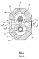
- Figure 1 shows a gear pump including a housing 10 defining an inlet port 12 and an outlet port 14 and being provided with a pair of identical parallel bores to define a chamber 16 within the housing 10.
- the gear pump is provided with a bearing arrangement comprising two pairs of substantially identical, part cylindrical bearing blocks 18, 20, only two of which are shown in Figure 1.
- Each of the first and second bearing blocks 18, 20 is mounted within a respective one of the parallel bores.
- the axially directed end faces of the bearing blocks 18, 20 sealingly abut end faces of two gears, the region of mesh of the gears lying between the inlet port 11 and the outlet port 12 of the pump.
- Shafts 22, 24 of the two meshed gears extend through further bores 26, 28 provided in the first and second bearing blocks 18, 20 respectively.
- the first gear shaft 22 is in connection with a splined drive shaft 26.
- Each of the first and second bearing blocks 18, 20 is provided with a pair of reliefs, 30 a , 30 b and 32 a , 32 b respectively, arranged such that one of the reliefs 30 a , 32 a communicates with the inlet port 12 and the other of the reliefs 30 b , 32 b communicates with the outlet port 14.
- the reliefs define therebetween respective bridge regions 34, 36 on each of the block end surfaces which prevent communication between the inlet port 12 and the outlet port 14. It is the bridge regions 34, 36 of the bearing blocks 18, 20 which are liable to cavitation erosion as a result of pressure changes within the inter-tooth volumes, as described previously.
- FIG 2 shows an enlarged view of the bearing arrangement suitable for use in the gear pump in Figure 1, and in which first and second insert members 38, 40 formed from an erosion resistant material are cast within the bridge regions 34, 36 respectively of the first and second bearing blocks 18, 20.
- first and second insert members 38, 40 are formed from stainless steel to specification AMS 5848.
- Each of the first and second bearing blocks 18, 20 includes a block housing, 18 a , 20 a respectively, cast from a reduced friction material, such as lead-bronze, using the method described hereinafter.
- the outer cylindrical surface of the bearing blocks 18, 20 is coated with a coating material (not shown in Figure 2) such as aluminium.
- a coating material such as aluminium.
- the axially directed end faces of the bearing blocks 18, 20 may be coated with a soft, low friction surface coating, for example lead indium.
- one or more of the regions of the bearing surface provided with the reliefs 30 a , 32 a , 30 b , 32 b is provided with a drilling or passage (not shown) in communication with a through bore (also not shown) provided in the respective bearing block 18, 20 to permit a supply of lubricating fluid within said bore.
- the passage are easy to drill by virtue of the twin block design.
- Figures 3 and 4 illustrate parts of the first bearing block 18 during an early stage in manufacture.
- the insert member 38 comprises a main body portion 38 a and a projection 38 b with a screw threaded bore 39.
- the projection 38 b is mounted upon a external support or jig (not shown) and a material, such as lead-bronze, is cast over the main body portion 38 a into a bell-shaped mould to cast the main body of the bearing block, resulting in a block housing 18 a having a cylindrical portion 18 b and an enlarged annular portion 18 c , as shown in Figure 4.
- the insert member 38 is provided with a screw threaded bore 39 which permits the insert member 38 to be mounted on the jig or support for the purpose of the casting process.
- the material from which the block housing 18 a is formed is a lead-bronze material such as Tokat 30.
- Figure 5 illustrates the first bearing block 18 during a subsequent stage in its manufacture, in which an upper region of the block housing 18 a is removed along line B-B using a conventional machining process.
- the machining of the upper region from the remainder of the block housing 18 a removes the projection 38 b from the main body portion 38 a of the insert member 38, thereby defining a flush bearing surface 44 (shown as a dashed line) which engages the gear teeth when the pump is in use.
- the aforementioned manufacturing process provides the bearing arrangement with a bearing surface 44 comprising a first region defined by a surface of the insert member 38 which is formed from erosion resistant material and a second region defined by the block housing 18 a which is formed from a friction reducing material.
- a bearing surface 44 comprising a first region defined by a surface of the insert member 38 which is formed from erosion resistant material and a second region defined by the block housing 18 a which is formed from a friction reducing material.
- the outer surface of the bearing block 18 is coated with a coating material 42, preferably aluminium.
- the aluminium coating material 42 is machined to give the desired outer profile of the bearing arrangement.
- the method by which the outer surface of the block housing 18 a of the bearing block 18 is coated may be that described in US 4523365.
- the aluminium coating 42 and the cast lead bronze is machined from the remainder of the bearing block 18 along dotted line C-C such that the outer surface of the bearing block 18 includes a region of steel defined by the insert member 38 which, when the bearing arrangement is assembled, mates with the corresponding outer surface of the second bearing block 20 defined by the second insert member, thereby defining an erosion resistant bridge region 34, 36 to separate the inlet and outlet ports 12, 14 of the pump.
- the second bearing block 20 forming part of the bearing arrangement in Figure 2 may be manufactured using the same technique as described for the first bearing block 18. Appropriate passages may also be provided in the relieved regions 32 a , 32 b to provide a region of outlet pressure within the bore 28 of the second bearing block 20.
- the bearing arrangement By manufacturing the bearing arrangement using the method of the present invention, it is possible to ensure that the region of the bearing surface 44 defined by the block housings 18 a , 20 a is exactly flush with the region of the bearing surface 44 defined by the insert member 38. Furthermore, by casting the material of the block housings 18 a , 20 a onto their respective insert members 38 it is possible to ensure the insert members 38 are securely mounted within the bearing blocks without the need for separate locking members.
- insert members 38, 40 may be formed from an erosion resistant material other than steel.
- the bearing blocks may be cast from any reduced friction material having properties which make it suitable for use as a bearing surface for gears, and need not be formed from lead-bronze.
Landscapes
- Engineering & Computer Science (AREA)
- Mechanical Engineering (AREA)
- General Engineering & Computer Science (AREA)
- Rotary Pumps (AREA)
- Details And Applications Of Rotary Liquid Pumps (AREA)
Description
providing an insert member, including a projection, formed from an erosion resistant material,
casting a reduced friction material over the insert member, to provide a cast block housing, such that the projection protrudes from an end face of the cast block housing,
machining the end face of the cast block housing from which the projection protrudes such that the projection is detached from the remainder of the insert member, thereby to define an axially directed bearing surface comprising a first region defined by the insert member and a second region defined by the cast block housing, wherein the first region is substantially flush with the second region.
Claims (9)
- A bearing arrangement for a gear pump comprises first and second separate bearing blocks (18, 20) each having a respective block housing (18a, 20a), the first and second bearing blocks (18, 20) together defining an axially directed bearing surface including a bridge region (34, 36) formed from an erosion resistant material which acts to separate inlet and outlet ports (12, 14) of the pump and a second region formed from a reduced friction material, wherein the bridge region (36, 40) is defined by first and second insert members (38, 40) cast within respective ones of the block housings (18a, 20a), the first and second bearing blocks (18, 20) being arranged such that respective surfaces of the first and second insert members (38, 40) mate with one another, the first and second insert members (38, 40) being arranged such that the bridge region (34, 36) of the bearing surface is flush with the second region.
- A bearing arrangement as claimed in Claim 1, wherein the erosion resistant material is stainless steel.
- A bearing arrangement as claimed in Claim 1 or Claim 2, wherein the block housings are cast from a lead-bronze material.
- A bearing arrangement as claimed in any of Claims 1 to 3, wherein each of the bearing blocks (18, 20) is provided with an inlet relief (30a, 32a) in communication with the inlet (12) of the pump and an outlet relief (30b, 32b) in communication with the outlet (14) of the pump, the bridge region (34, 36) of the bearing surface being defined between the inlet and outlet reliefs (30a, 32a, 30b, 32b).
- A bearing arrangement as claimed in Claim 4, wherein one or more of the relieved portions (30a, 32a, 30b, 32b) of the bearing surface is provided with a drilling or passage which communicates with a through bore provided in the respective bearing block (18, 20) to permit a supply of lubricating fluid within said bore.
- The bearing arrangement as claimed in any of Claims 1 to 5, wherein one or more of the block housings (18a, 20a) is provided with a coating.
- A method of assembling a bearing arrangement for a gear pump comprises the steps of;
providing an insert member (38), including a projection (38a), formed from an erosion resistant material,
casting a reduced friction material over the insert member (38), to provide a cast block housing (18a), such that the projection (38a) protrudes from an end face of the cast block housing (18a),
machining the end face of the cast block housing (18a) from which the projection (38a) protrudes such that the projection (38a) is detached from the remainder of the insert member (38), thereby to define an axially directed bearing surface (44) comprising a bridge region (34) defined by the insert member (38) and a second region defined by the cast block housing (18a), wherein the bridge region (34) is substantially flush with the second region. - The method as claimed in Claim 7, including the further step of coating an outer surface of the cast block housing (18a) with a coating material (42).
- The method as claimed in Claim 8, further including the step of machining the coated outer surface of the bearing block (18a) to achieve the desired profile.
Applications Claiming Priority (2)
| Application Number | Priority Date | Filing Date | Title |
|---|---|---|---|
| GBGB0114434.4A GB0114434D0 (en) | 2001-06-14 | 2001-06-14 | Bearing arrangement |
| GB0114434 | 2001-06-14 |
Publications (3)
| Publication Number | Publication Date |
|---|---|
| EP1267076A2 EP1267076A2 (en) | 2002-12-18 |
| EP1267076A3 EP1267076A3 (en) | 2003-04-23 |
| EP1267076B1 true EP1267076B1 (en) | 2004-09-15 |
Family
ID=9916521
Family Applications (1)
| Application Number | Title | Priority Date | Filing Date |
|---|---|---|---|
| EP02254073A Expired - Lifetime EP1267076B1 (en) | 2001-06-14 | 2002-06-12 | Bearing arrangement |
Country Status (4)
| Country | Link |
|---|---|
| US (1) | US6716010B2 (en) |
| EP (1) | EP1267076B1 (en) |
| DE (1) | DE60201216T2 (en) |
| GB (1) | GB0114434D0 (en) |
Families Citing this family (13)
| Publication number | Priority date | Publication date | Assignee | Title |
|---|---|---|---|---|
| GB0509866D0 (en) * | 2005-05-13 | 2005-06-22 | Goodrich Control Sys Ltd | Gear pump arrangement |
| US8998496B2 (en) * | 2012-03-30 | 2015-04-07 | Imo Industries, Inc. | Gear pump with asymmetrical dual bearing |
| US9482225B2 (en) | 2012-06-04 | 2016-11-01 | Honeywell International Inc. | Gear pump, pumping apparatus including the same, and aircraft fuel system including gear pump |
| US9303644B2 (en) | 2013-11-26 | 2016-04-05 | Woodward, Inc. | Gear pump bearing dam |
| US9874208B2 (en) * | 2015-01-21 | 2018-01-23 | Hamilton Sunstrand Corporation | Bearing faces with fluid channels for gear pumps |
| GB201614326D0 (en) | 2016-08-22 | 2016-10-05 | Rolls-Royce Controls And Data Services Ltd | Gear pump bearing |
| GB201614327D0 (en) | 2016-08-22 | 2016-10-05 | Rolls-Royce Controls And Data Services Ltd | Gear pump bearing |
| GB201714578D0 (en) | 2017-09-11 | 2017-10-25 | Rolls Royce Plc | Gear pump bearing |
| US11060559B2 (en) * | 2018-06-11 | 2021-07-13 | Eaton Intelligent Power Limited | Bi-metallic journal bearing with additive manufactured sleeve |
| US10584747B1 (en) * | 2018-12-03 | 2020-03-10 | Hamilton Sundstrand Corporation | Fuel pump bearing with non-concentric inner diameters |
| US10962059B2 (en) * | 2019-06-17 | 2021-03-30 | Hamilton Sundstrand Corporation | Bearing with an eccentric seal groove |
| US12247617B2 (en) | 2022-12-08 | 2025-03-11 | Hamilton Sundstrand Corporation | Cavitation resistant journal bearing |
| GB202318901D0 (en) | 2023-12-12 | 2024-01-24 | Rolls Royce Plc | Bearing block for a gear pump assembly |
Family Cites Families (11)
| Publication number | Priority date | Publication date | Assignee | Title |
|---|---|---|---|---|
| US2982220A (en) * | 1957-11-29 | 1961-05-02 | Commercial Shearing | Thrust plates for rotary pumps and motors |
| US3073251A (en) * | 1958-02-28 | 1963-01-15 | Bosch Gmbh Robert | Hydraulic machines |
| DE1810314A1 (en) * | 1968-11-22 | 1970-06-11 | Bosch Gmbh Robert | Gear pump or motor |
| US3778200A (en) * | 1972-02-02 | 1973-12-11 | Weatherhead Co | Rotary fluid pump or motor |
| US3981646A (en) * | 1973-03-15 | 1976-09-21 | Lucas Aerospace Limited | Gear pumps and motors |
| DE2510496C3 (en) * | 1975-03-11 | 1978-07-20 | Robert Bosch Gmbh, 7000 Stuttgart | Gear machine (pump or motor) |
| GB2012876B (en) | 1978-01-18 | 1982-04-21 | Lucas Industries Ltd | Hydraulic pumps |
| US4311445A (en) | 1979-10-30 | 1982-01-19 | Tyrone Hydraulics, Inc. | Contaminant resistant gear pumps and motors with wear inserts |
| GB2109821B (en) | 1981-08-05 | 1985-08-14 | Lucas Ind Plc | Method of manufacturing bearing blocks |
| DE3766245D1 (en) * | 1987-04-24 | 1990-12-20 | Vickers Systems Gmbh | GEAR PUMP OR MOTOR FOR FLUIDE. |
| US5022837A (en) * | 1989-11-13 | 1991-06-11 | Sta-Rite Industries, Inc. | Seal arrangement for a gear machine |
-
2001
- 2001-06-14 GB GBGB0114434.4A patent/GB0114434D0/en not_active Ceased
-
2002
- 2002-06-12 DE DE60201216T patent/DE60201216T2/en not_active Expired - Lifetime
- 2002-06-12 EP EP02254073A patent/EP1267076B1/en not_active Expired - Lifetime
- 2002-06-14 US US10/172,800 patent/US6716010B2/en not_active Expired - Lifetime
Also Published As
| Publication number | Publication date |
|---|---|
| DE60201216T2 (en) | 2005-09-29 |
| EP1267076A3 (en) | 2003-04-23 |
| DE60201216D1 (en) | 2004-10-21 |
| EP1267076A2 (en) | 2002-12-18 |
| US6716010B2 (en) | 2004-04-06 |
| US20030053923A1 (en) | 2003-03-20 |
| GB0114434D0 (en) | 2001-08-08 |
Similar Documents
| Publication | Publication Date | Title |
|---|---|---|
| US6716010B2 (en) | Bearing arrangement | |
| EP2831435B1 (en) | Gear pump with asymmetrical dual bearing | |
| EP1464837B1 (en) | Balanced pressure gerotor fuel pump | |
| US2881704A (en) | Pressure loaded pump construction | |
| GB2191543A (en) | Twin pump of the internally- meshing gear type | |
| US7607906B2 (en) | Gear pump arrangement with erosion resistant insert | |
| JPH01247767A (en) | Internal contact gear motor | |
| US20210355939A1 (en) | External gear pump | |
| EP0046293A2 (en) | Rotary fluid pressure device and valve-seating mechanism therefor | |
| US7717689B2 (en) | Rotor apparatus of pump including a drive shaft with a plurality of arcuate circumferential surface sections | |
| JP2743616B2 (en) | Gear pump | |
| US4266915A (en) | Gear pumps and motors | |
| KR20070073792A (en) | Pump with selectable outlet pressure | |
| JP3602275B2 (en) | Gear pump | |
| KR20170093218A (en) | Gerotor pump | |
| US6997689B2 (en) | Offset bearing for extended fuel pump life | |
| WO1987003937A1 (en) | Gear pump | |
| EP1857679A1 (en) | Vane pump | |
| RU2154193C2 (en) | Gear pump | |
| CN223707902U (en) | Internal gear pump | |
| JP6402862B2 (en) | Gear pump or gear motor | |
| JP2024178602A (en) | External gear pump | |
| JP2016020661A (en) | Pump device | |
| JP2009052467A (en) | Gear pump | |
| JP3574717B2 (en) | Gear pump |
Legal Events
| Date | Code | Title | Description |
|---|---|---|---|
| PUAI | Public reference made under article 153(3) epc to a published international application that has entered the european phase |
Free format text: ORIGINAL CODE: 0009012 |
|
| AK | Designated contracting states |
Kind code of ref document: A2 Designated state(s): AT BE CH CY DE DK ES FI FR GB GR IE IT LI LU MC NL PT SE TR |
|
| AX | Request for extension of the european patent |
Free format text: AL;LT;LV;MK;RO;SI |
|
| PUAL | Search report despatched |
Free format text: ORIGINAL CODE: 0009013 |
|
| AK | Designated contracting states |
Designated state(s): AT BE CH CY DE DK ES FI FR GB GR IE IT LI LU MC NL PT SE TR |
|
| AX | Request for extension of the european patent |
Extension state: AL LT LV MK RO SI |
|
| RAP1 | Party data changed (applicant data changed or rights of an application transferred) |
Owner name: GOODRICH CONTROL SYSTEMS LIMITED |
|
| 17P | Request for examination filed |
Effective date: 20030729 |
|
| AKX | Designation fees paid |
Designated state(s): DE FR GB |
|
| GRAP | Despatch of communication of intention to grant a patent |
Free format text: ORIGINAL CODE: EPIDOSNIGR1 |
|
| GRAS | Grant fee paid |
Free format text: ORIGINAL CODE: EPIDOSNIGR3 |
|
| GRAA | (expected) grant |
Free format text: ORIGINAL CODE: 0009210 |
|
| AK | Designated contracting states |
Kind code of ref document: B1 Designated state(s): DE FR GB |
|
| REG | Reference to a national code |
Ref country code: GB Ref legal event code: FG4D |
|
| REG | Reference to a national code |
Ref country code: IE Ref legal event code: FG4D |
|
| REF | Corresponds to: |
Ref document number: 60201216 Country of ref document: DE Date of ref document: 20041021 Kind code of ref document: P |
|
| PLBE | No opposition filed within time limit |
Free format text: ORIGINAL CODE: 0009261 |
|
| STAA | Information on the status of an ep patent application or granted ep patent |
Free format text: STATUS: NO OPPOSITION FILED WITHIN TIME LIMIT |
|
| ET | Fr: translation filed | ||
| 26N | No opposition filed |
Effective date: 20050616 |
|
| REG | Reference to a national code |
Ref country code: DE Ref legal event code: R081 Ref document number: 60201216 Country of ref document: DE Owner name: GOODRICH CONTROL SYSTEMS, GB Free format text: FORMER OWNER: GOODRICH CONTROL SYSTEMS LTD., LUTON, GB Effective date: 20140220 Ref country code: DE Ref legal event code: R081 Ref document number: 60201216 Country of ref document: DE Owner name: GOODRICH CONTROL SYSTEMS, SOLIHULL, GB Free format text: FORMER OWNER: GOODRICH CONTROL SYSTEMS LTD., LUTON, BEDFORDSHIRE, GB Effective date: 20140220 |
|
| REG | Reference to a national code |
Ref country code: FR Ref legal event code: CJ Effective date: 20140313 Ref country code: FR Ref legal event code: CD Owner name: GOODRICH CONTROL SYSTEMS Effective date: 20140313 |
|
| REG | Reference to a national code |
Ref country code: FR Ref legal event code: PLFP Year of fee payment: 15 |
|
| REG | Reference to a national code |
Ref country code: FR Ref legal event code: PLFP Year of fee payment: 16 |
|
| REG | Reference to a national code |
Ref country code: FR Ref legal event code: PLFP Year of fee payment: 17 |
|
| PGFP | Annual fee paid to national office [announced via postgrant information from national office to epo] |
Ref country code: FR Payment date: 20190522 Year of fee payment: 18 |
|
| PGFP | Annual fee paid to national office [announced via postgrant information from national office to epo] |
Ref country code: DE Payment date: 20200519 Year of fee payment: 19 |
|
| PGFP | Annual fee paid to national office [announced via postgrant information from national office to epo] |
Ref country code: GB Payment date: 20200525 Year of fee payment: 19 |
|
| PG25 | Lapsed in a contracting state [announced via postgrant information from national office to epo] |
Ref country code: FR Free format text: LAPSE BECAUSE OF NON-PAYMENT OF DUE FEES Effective date: 20200630 |
|
| REG | Reference to a national code |
Ref country code: DE Ref legal event code: R119 Ref document number: 60201216 Country of ref document: DE |
|
| GBPC | Gb: european patent ceased through non-payment of renewal fee |
Effective date: 20210612 |
|
| PG25 | Lapsed in a contracting state [announced via postgrant information from national office to epo] |
Ref country code: GB Free format text: LAPSE BECAUSE OF NON-PAYMENT OF DUE FEES Effective date: 20210612 Ref country code: DE Free format text: LAPSE BECAUSE OF NON-PAYMENT OF DUE FEES Effective date: 20220101 |