EP2831435B1 - Gear pump with asymmetrical dual bearing - Google Patents
Gear pump with asymmetrical dual bearing Download PDFInfo
- Publication number
- EP2831435B1 EP2831435B1 EP13767455.2A EP13767455A EP2831435B1 EP 2831435 B1 EP2831435 B1 EP 2831435B1 EP 13767455 A EP13767455 A EP 13767455A EP 2831435 B1 EP2831435 B1 EP 2831435B1
- Authority
- EP
- European Patent Office
- Prior art keywords
- bearing
- grooves
- pump
- face
- sealing
- Prior art date
- Legal status (The legal status is an assumption and is not a legal conclusion. Google has not performed a legal analysis and makes no representation as to the accuracy of the status listed.)
- Active
Links
Images


Classifications
-
- F—MECHANICAL ENGINEERING; LIGHTING; HEATING; WEAPONS; BLASTING
- F16—ENGINEERING ELEMENTS AND UNITS; GENERAL MEASURES FOR PRODUCING AND MAINTAINING EFFECTIVE FUNCTIONING OF MACHINES OR INSTALLATIONS; THERMAL INSULATION IN GENERAL
- F16C—SHAFTS; FLEXIBLE SHAFTS; ELEMENTS OR CRANKSHAFT MECHANISMS; ROTARY BODIES OTHER THAN GEARING ELEMENTS; BEARINGS
- F16C33/00—Parts of bearings; Special methods for making bearings or parts thereof
- F16C33/02—Parts of sliding-contact bearings
- F16C33/04—Brasses; Bushes; Linings
-
- F—MECHANICAL ENGINEERING; LIGHTING; HEATING; WEAPONS; BLASTING
- F01—MACHINES OR ENGINES IN GENERAL; ENGINE PLANTS IN GENERAL; STEAM ENGINES
- F01C—ROTARY-PISTON OR OSCILLATING-PISTON MACHINES OR ENGINES
- F01C21/00—Component parts, details or accessories not provided for in groups F01C1/00 - F01C20/00
- F01C21/02—Arrangements of bearings
-
- F—MECHANICAL ENGINEERING; LIGHTING; HEATING; WEAPONS; BLASTING
- F04—POSITIVE - DISPLACEMENT MACHINES FOR LIQUIDS; PUMPS FOR LIQUIDS OR ELASTIC FLUIDS
- F04C—ROTARY-PISTON, OR OSCILLATING-PISTON, POSITIVE-DISPLACEMENT MACHINES FOR LIQUIDS; ROTARY-PISTON, OR OSCILLATING-PISTON, POSITIVE-DISPLACEMENT PUMPS
- F04C15/00—Component parts, details or accessories of machines, pumps or pumping installations, not provided for in groups F04C2/00 - F04C14/00
- F04C15/0088—Lubrication
-
- F—MECHANICAL ENGINEERING; LIGHTING; HEATING; WEAPONS; BLASTING
- F04—POSITIVE - DISPLACEMENT MACHINES FOR LIQUIDS; PUMPS FOR LIQUIDS OR ELASTIC FLUIDS
- F04C—ROTARY-PISTON, OR OSCILLATING-PISTON, POSITIVE-DISPLACEMENT MACHINES FOR LIQUIDS; ROTARY-PISTON, OR OSCILLATING-PISTON, POSITIVE-DISPLACEMENT PUMPS
- F04C2/00—Rotary-piston machines or pumps
- F04C2/08—Rotary-piston machines or pumps of intermeshing-engagement type, i.e. with engagement of co-operating members similar to that of toothed gearing
- F04C2/12—Rotary-piston machines or pumps of intermeshing-engagement type, i.e. with engagement of co-operating members similar to that of toothed gearing of other than internal-axis type
- F04C2/14—Rotary-piston machines or pumps of intermeshing-engagement type, i.e. with engagement of co-operating members similar to that of toothed gearing of other than internal-axis type with toothed rotary pistons
- F04C2/18—Rotary-piston machines or pumps of intermeshing-engagement type, i.e. with engagement of co-operating members similar to that of toothed gearing of other than internal-axis type with toothed rotary pistons with similar tooth forms
-
- F—MECHANICAL ENGINEERING; LIGHTING; HEATING; WEAPONS; BLASTING
- F16—ENGINEERING ELEMENTS AND UNITS; GENERAL MEASURES FOR PRODUCING AND MAINTAINING EFFECTIVE FUNCTIONING OF MACHINES OR INSTALLATIONS; THERMAL INSULATION IN GENERAL
- F16C—SHAFTS; FLEXIBLE SHAFTS; ELEMENTS OR CRANKSHAFT MECHANISMS; ROTARY BODIES OTHER THAN GEARING ELEMENTS; BEARINGS
- F16C17/00—Sliding-contact bearings for exclusively rotary movement
- F16C17/26—Systems consisting of a plurality of sliding-contact bearings
-
- F—MECHANICAL ENGINEERING; LIGHTING; HEATING; WEAPONS; BLASTING
- F16—ENGINEERING ELEMENTS AND UNITS; GENERAL MEASURES FOR PRODUCING AND MAINTAINING EFFECTIVE FUNCTIONING OF MACHINES OR INSTALLATIONS; THERMAL INSULATION IN GENERAL
- F16C—SHAFTS; FLEXIBLE SHAFTS; ELEMENTS OR CRANKSHAFT MECHANISMS; ROTARY BODIES OTHER THAN GEARING ELEMENTS; BEARINGS
- F16C33/00—Parts of bearings; Special methods for making bearings or parts thereof
- F16C33/02—Parts of sliding-contact bearings
- F16C33/04—Brasses; Bushes; Linings
- F16C33/06—Sliding surface mainly made of metal
- F16C33/10—Construction relative to lubrication
- F16C33/1025—Construction relative to lubrication with liquid, e.g. oil, as lubricant
- F16C33/106—Details of distribution or circulation inside the bearings, e.g. details of the bearing surfaces to affect flow or pressure of the liquid
- F16C33/1065—Grooves on a bearing surface for distributing or collecting the liquid
-
- F—MECHANICAL ENGINEERING; LIGHTING; HEATING; WEAPONS; BLASTING
- F16—ENGINEERING ELEMENTS AND UNITS; GENERAL MEASURES FOR PRODUCING AND MAINTAINING EFFECTIVE FUNCTIONING OF MACHINES OR INSTALLATIONS; THERMAL INSULATION IN GENERAL
- F16C—SHAFTS; FLEXIBLE SHAFTS; ELEMENTS OR CRANKSHAFT MECHANISMS; ROTARY BODIES OTHER THAN GEARING ELEMENTS; BEARINGS
- F16C33/00—Parts of bearings; Special methods for making bearings or parts thereof
- F16C33/72—Sealings
- F16C33/74—Sealings of sliding-contact bearings
-
- F—MECHANICAL ENGINEERING; LIGHTING; HEATING; WEAPONS; BLASTING
- F04—POSITIVE - DISPLACEMENT MACHINES FOR LIQUIDS; PUMPS FOR LIQUIDS OR ELASTIC FLUIDS
- F04C—ROTARY-PISTON, OR OSCILLATING-PISTON, POSITIVE-DISPLACEMENT MACHINES FOR LIQUIDS; ROTARY-PISTON, OR OSCILLATING-PISTON, POSITIVE-DISPLACEMENT PUMPS
- F04C15/00—Component parts, details or accessories of machines, pumps or pumping installations, not provided for in groups F04C2/00 - F04C14/00
- F04C15/0003—Sealing arrangements in rotary-piston machines or pumps
- F04C15/0034—Sealing arrangements in rotary-piston machines or pumps for other than the working fluid, i.e. the sealing arrangements are not between working chambers of the machine
- F04C15/0038—Shaft sealings specially adapted for rotary-piston machines or pumps
-
- F—MECHANICAL ENGINEERING; LIGHTING; HEATING; WEAPONS; BLASTING
- F04—POSITIVE - DISPLACEMENT MACHINES FOR LIQUIDS; PUMPS FOR LIQUIDS OR ELASTIC FLUIDS
- F04C—ROTARY-PISTON, OR OSCILLATING-PISTON, POSITIVE-DISPLACEMENT MACHINES FOR LIQUIDS; ROTARY-PISTON, OR OSCILLATING-PISTON, POSITIVE-DISPLACEMENT PUMPS
- F04C2240/00—Components
- F04C2240/50—Bearings
- F04C2240/52—Bearings for assemblies with supports on both sides
-
- F—MECHANICAL ENGINEERING; LIGHTING; HEATING; WEAPONS; BLASTING
- F04—POSITIVE - DISPLACEMENT MACHINES FOR LIQUIDS; PUMPS FOR LIQUIDS OR ELASTIC FLUIDS
- F04C—ROTARY-PISTON, OR OSCILLATING-PISTON, POSITIVE-DISPLACEMENT MACHINES FOR LIQUIDS; ROTARY-PISTON, OR OSCILLATING-PISTON, POSITIVE-DISPLACEMENT PUMPS
- F04C2240/00—Components
- F04C2240/50—Bearings
- F04C2240/56—Bearing bushings or details thereof
Definitions
- the disclosure generally relates to bearings for use in pump assemblies, and more particularly to an asymmetrical dual bearing for use in pumps such as a metering pump.
- Gear pumps typically include a housing or plate that holds a set of intermeshing gears. As the gears turn, fluid moves between the gear teeth and the housing and is expelled out the pump due to the intermeshing of the gears.
- the gears are attached to shafts that run axially from the gear faces, and these shafts must run on one or more bearing surfaces.
- Gear pumps find application in a variety of industries. In the case of gear pumps used for polymer extrusion it is important to have the fluid ports as near to the entrance and outlet of the gear "mesh” as possible in order to reduce the amount of time the polymer resides in the pump, and to minimize the total amount of heat added to the polymer by the pump.
- the housing or plate that contains the gear set includes one or more ports machined into its side.
- the housing or plate may be substantially wider than the gear set to receive bolts of a flange that attaches to the pump. This extra housing space may accommodate bearings for supporting the gear shafts. Providing discrete shaft bearings allows for better shaft alignment than arrangements in which the shafts are simply mounted in separate plates attached to the gear housing.
- the traditional bearings may also include features used to help remove trapped fluid from the gear mesh. Often such features are machined on the individual bearing pieces as two separate features. Because the bearing assemblies are made up of so many individual bearing pieces, it is easy for these features to be misaligned during manufacturing and installation. Such misalignment can cause the pump to perform in a less than desired manner. Moreover, the large number of pieces used in the bearing assembly, and the importance of the inter-fitting of the bearing pairs in the bearings into the bearing cavity, makes assembly of the pump very difficult.
- an improved bearing assembly for pumps in general and gear pumps in particular.
- Such an improved bearing assembly should be easy to install, and should reduce the total number of individual parts required for assembly.
- the improved bearing assembly should also include features that will reliably enable trapped fluid to be removed from the gear mesh.
- a bearing and a pump are provided according to claims 1 and 9, respectively.
- An asymmetrical bearing for use in supporting a shaft of a pump.
- a single asymmetrical bearing is provided on each side of a pair of gears in a gear pump.
- the single asymmetrical bearing may support both the drive shaft and the shaft of the driven gear.
- the asymmetry of the bearing acts to limit the number of degrees of freedom the bearing has during installation.
- a single bearing can be used on each side of the pump.
- the single piece design reduces the total number of parts in the pump, and greatly simplifies the assembly of the pump.
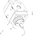
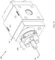
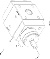
- the gear pump 1 may include a central gear plate 2, front and rear plates 4, 6, a seal plate 8 and a drive shaft 10.
- An inlet port (not shown) and an outlet port 12 may be formed in the central gear plate for moving fluid through the pump 1.
- the inlet and outlet ports may be coupled to inlet and outlet piping or tubing via an o-ring connection.
- the central gear plate 2 may include a recess having a flat face portion 13a and first and second angled surfaces 13b, 13c for sealing engagement with an o-ring (not shown).
- the first and second angled surfaces 13b, 13c comprise 12-sided geometric shapes rather than smooth surfaces. The use of a 12-sides geometric shape may facilitate surface machining during manufacture.
- the pump 1 may be fixed in its assembled form via a plurality of fasteners, which in the illustrated embodiment are socket head cap screws 14, 16.
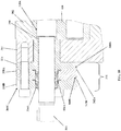
- FIG. 2 shows the pump 1 in exploded form.
- the drive shaft 10 includes a first gear 18 which intermeshes with a second gear 20 of a driven shaft 22.
- First and second asymmetrical bearings 24, 26 are positioned on opposite sides of the first and second gears 18, 20 and receive the drive shaft 10 and drive shaft 22 via respective bores 28A, B, 30A, B.
- the first and second gears 18, 20 and first and second asymmetrical bearings 24, 26 are received within an asymmetrical opening 32 in the central gear plate 2.
- the asymmetrical opening 32 is shaped to correspond to the shape of the asymmetrical bearings 24, 26, which facilitates installation of the bearings and maintains their alignment during operation.
- the seal plate 8 may fix a variety of sealing elements to the front plate 4 to prevent fluid leakage around the drive shaft 10.
- the sealing elements may include an o-ring 34, a lip seal 36 and a sealing sleeve 38, all of which may be received in a suitably configured recess 40 in the front plate 4.
- FIGS. 3 and 4 show the internal inter-relation of components of the pump 1 when assembled.
- the o-ring 34 is sandwiched between a rim portion 40 of the sealing sleeve 38 and a shoulder portion 42 of the front plate 4.
- the lip seal 36 is sandwiched between first and second shoulder portions 44, 46 of the seal plate 8 and a front face 48 of the sealing sleeve 38.
- An inner bore 50 of the sealing sleeve 38 includes a plurality of grooves 52 for sealing against the surface of the rotating drive shaft 10.
- the grooves 52 comprise a helical groove which allows the sealing sleeve 38 to act as a screw-type pump during operation.
- the shaft's rotary motion forces the fluid into the groove 52. This creates a pressure greater than the pressure forcing the fluid out of the pump, and forces the fluid back toward the central gear plate 2.
- the pumped fluid is prevented from leaking past the drive shaft 10 during operation.
- the outside diameter of the sealing sleeve 38 is sized to loosely fit within bore 80 of the front plate 4, while the inside diameter of the sealing sleeve 38 is sized to fit closely to the shaft 10.
- the sealing sleeve 38 is compliantly mounted between the o-ring 34 and the lip seal 36 so that sealing sleeve 38 can always align to the shaft 10. Thus arranged, the pumped fluid is prevented from leaking past the drive shaft 10 during operation.
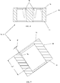
- the bearing 24 may be a generally flat structure having first and second faces 54, 56 and a side surface 58 that is flat on a first side 60 and forms a pair of lobes 62, 64 on an opposite second side.
- the resulting configuration gives the bearing 24 the appearance of the letter "B.”
- the first face 54 may include first and second grooves 66, 68 that run from a common position on the first side 60 and which each intersect with one of the bores 28A, 28B that receive the drive shaft 10 and the driven shaft 22.
- a notch 70 may be provided on the first side 60 where the grooves 66, 68 meet. This notch 70 may run from the first face 54 to the second face 56.
- the first and second grooves 66, 68 (and notch 70) may have any of a variety of cross-sectional shapes and depths, as desired for the particular application.
- the grooves are about 0.010 inches deep and about 0.100 inches wide, though this is not critical and the grooves may be of different shapes and depths as desired.
- the groove width may be about 1/20 th of the radius of curvature of one or both lobes 62, 64, while the groove depth may be about 1/200 th of the radius of curvature of one or both lobes 64.
- the grooves could instead be disposed on a portion of the front plate 4.
- the notch 70 could be provided in the gear plate 2 in lieu of the bearing 24.
- FIG. 7 shows that grooves may also be provided in the second face 56 of the asymmetrical bearing 24.
- a third groove 72 may run between the bores 28A, 28B and may be bisected by a fourth groove 74 that runs from a position on the side surface 58 where the lobes 62, 64 intersect to a point generally between the centers of the bores 28A, 28B.
- the third groove 72 is offset with respect to the centers of the bores 28A, 28B so that it intersects the bores roughly at a tangent. This is not critical, however, and third groove 72 could be angled toward the centers of one or both bores.
- the grooves are about 0.010 inches deep and about 0.100 inches wide, though this is not critical and the grooves may be of different shapes and depths as desired.
- Each of the bores 28A, 28B may also be provided with a lubrication groove 76 in the region in which the bores intersect with third groove 72.
- This lubrication groove 76 may be formed as a portion of a circle 78 that is offset from a center "C" of the respective bore by an offset distance "OD,” and at an angle " ⁇ " with respect to a line perpendicular to the bearing centerline (represented by section line 8-8). In one embodiment, " ⁇ " is about 35 degrees. As can be seen in FIG.
- a small angled transition may be applied to the profile of the entire bearing as well as the profile of the housing or plate where the bearing is installed. These transitions may help allow any angular misalignment to self-correct itself and allow smooth assembly of the bearing in the housing or plate.
- Lubrication of the shafts is always a priority in gear pumps, and the shafts are typically lubricated by fluid being pumped. While many efforts have been made to provide flow paths for the fluid through the bearings, the disclosed design is unique in that one of the features used to help promote fluid flow through the bearings also is used to manufacture the part.
- This notch 70 functionally serves to fluidly connect the inlet port are with surface 54, and may act as a return flow path for the fluid used to lubricate the bearings.
- high pressure fluid is directed along the second face 56 of the bearing 24, into a groove in the bores 28A, 28B in the bearing 24, down the first face 54 of the bearing to the notch 70 and finally returns to the low pressure inlet of the pump.
- an axial groove is created by the lubrication groove 76. It will be appreciated that other methods to convey the fluid to the low pressure inlet may be employed, such as holes in the gear housing plate.
- the orientation of the asymmetric design is important in promoting fluid flow in the pump.
- the disclosed asymmetric design creates a cavity on the inlet for the fluid being pumped to collect before being carried around the gear pocket by the gear form. This pool of fluid helps to ensure that the pump does not starve itself during operation and will run at its maximum capacity.
- the groove 74 is also used to help remove trapped fluid from the gear mesh, extends from a critical dimension off of the centerline of the pump, depending on the gear form, and extends the entire length of the part in a cylindrical fashion.
- the gear pump 100 may be similar to the gear pump 1 described in relation to FIGS. 1-4 .
- the pump 100 may include a central gear plate 102, front and rear plates 104, 106, a seal assembly 108 and a drive shaft 110.
- An inlet port (not shown) and an outlet port 112 may be formed in the central gear plate for moving fluid through the pump 100.
- the pump 1 may be fixed in its assembled form via a plurality of fasteners, which in the illustrated embodiment are socket head cap screws 114, 116.
- FIG. 11 shows the pump 100 in exploded form.
- a drive shaft 110 includes a first gear 118 which intermeshes with a second gear 120 of a driven shaft 122.
- First and second asymmetrical bearings 124, 126 are positioned on opposite sides of the first and second gears 118, 120 and receive the drive shaft 110 and driven shaft 122 via respective bores 128A, B, 130A, B, respectively.
- the first and second gears 118, 120 and first and second asymmetrical bearings 124, 126 are received within an asymmetrical opening 132 in the central gear plate 102.
- the asymmetrical opening 132 is shaped to correspond to the shape of the asymmetrical bearings 124, 126, which may facilitate installation of the bearings and maintain their alignment during operation.
- the first and second asymmetrical bearings 124, 126 can have any of the features of the bearings 24, 26 described in relation to FIGS. 5-9 .
- the seal arrangement 108 may include a plurality of sealing elements configured to prevent fluid leakage around the drive shaft 110.
- the sealing arrangement 108 comprises a lip seal housing 134, a lip seal 136 and a sealing sleeve 138, which may be fixed together in the stacked relation shown in FIG. 12-13 .
- the lip seal 136 may be held in a recess formed in the lip seal housing 134.
- a circumferential flange portion 140 of the lip seal 136 may be sandwiched between the lip seal housing 134 and a front surface 142 of the sealing sleeve 138.
- the lip seal 136 may form a radial seal around the drive shaft 110, and may form a face seal between the sealing sleeve 138 and the lip seal housing 134 (the face seal is facilitated by the flange portion 140 of the lip seal 136).
- a cylindrical body portion 144 of the sealing sleeve 138 may be received in an opening 146 of the front plate 104.
- the distal end 148 of the cylindrical body portion 144 includes a reduced diameter portion 150 that is sized to be received within the bore 128A of asymmetric bearing 124 to align the sealing sleeve within the pump 100.
- central bore 152 of the sealing sleeve 138 is precisely located relative to the outer diameter 156 of the driveshaft 110, thus reducing the likelihood for contact between the drive shaft and the sealing sleeve, and also minimizing any eccentricity between the drive shaft and the sealing sleeve.
- the sealing sleeve 138, lip seal 136 and lip seal housing 134 may all have corresponding central bores which receive a portion of the drive shaft 110 therethrough.
- the central bore 152 of the sealing sleeve 138 may include a helical groove 154 which allows the sealing sleeve to act as a screw-type pump during operation, as previously described in relation to the embodiment of FIGS. 1-4 .
- the pump 100 may further include alignment, or "piloting" features on the sealing elements, thus improving concentricity between the axes of the sealing elements and the axis of the shaft, which are otherwise independent features.
- the sealing sleeve 138 includes a flange portion 158 having a forward facing circumferential alignment recess 160 disposed adjacent to the perimeter of the flange portion.
- this alignment recess 160 can be used to align one or more secondary seals.
- the alignment recess 160 receives a rearward protruding circumferential lip portion 162 of the lip seal housing 134.
- the lip seal housing 134 includes its own alignment recess 164 disposed on a forward facing portion of the housing. This alignment recess 164 can be used to align additional sealing elements (not shown), as desired.
- the sealing sleeve 138 may be bolted to the front plate 104. There may be a loose clearance fit between the outer surface of the cylindrical body portion 144 of the sealing sleeve and the front plate 104. Since the sealing sleeve is not tightly located on the front plate 104, this loose fit reduces the chances of pump binding during assembly, when the bolts 114 are tightened.
- the sealing sleeve 138 and lip seal housing 134 can be bolted to the front plate 104 without the cylindrical body portion 144 of the sealing sleeve touching the through bore in the front plate 104.
- the locating feature on the sealing sleeve 138 (i.e., the interaction between the reduced diameter portion 150 of the sealing sleeve and the bore 128A of asymmetric bearing 124) can be used to align this assembly to the rest of the pump.
- the front plate 104, seal assembly 108 and remainder of the pump components can then be fastened together with fasteners 116.
- the disclosed arrangement can improve sealing performance, and can make pump assembly easier.
- the gear pump 200 may include some or all of the features of the previously described pumps 1, 100, including central gear plate 202, front and rear plates 204, 206, a seal assembly 208 and a drive shaft 210.
- An inlet port (not shown) and an outlet port 212 may be formed in the central gear plate for moving fluid through the pump 200.
- the pump 200 may be fixed in its assembled form via a plurality of fasteners 214, 216.
- the pump 200 may also include first and second asymmetrical bearings 224, 226 that engage the drive shaft 210 and a driven shaft 222.
- the asymmetrical bearings 224, 226 may have any of the features of the bearings 24, 26 described in relation to FIGS. 5-9 .
- the seal assembly 208 of pump 200 may comprise a packing housing 234, packing seals 236A, B and a packing follower 238.
- This packing housing 234 has a bore defining an inside diameter "ID" that is larger than the outside diameter "OD" of the drive shaft 210.
- the packing housing 234 may also include a recess 235 formed at a forward end configured to receive a pair of packing seals 236A, B.
- the recess 235 may also receive a rearwardly projecting portion 237 of the packing follower 238.
- the rearwardly projecting portion 237 of the packing follower compresses the packing seals 236A, B within the recess 235 to provide a desired sealing engagement with the "OD" of the drive shaft 210. Compression of the packing seals 236A, B can be adjusted via fasteners 215.
- a cylindrical body portion 244 of the packing housing 234 may be received in an opening 246 of the front plate 204.
- a distal end 248 of the cylindrical body portion 244 includes a reduced diameter portion 250 that is sized to be received within the bore 228A of asymmetric bearing 224 to align the packing housing 234 within the pump 200.
- the "ID" of the packing housing 234 is precisely located relative to the outer diameter "OD" of the driveshaft 210, thus reducing the likelihood for contact between the drive shaft and the packing housing, and also minimizing any eccentricity between the drive shaft and the packing housing.
- the packing housing 234 also includes an alignment recess 264 disposed on a forward facing portion of the housing. This alignment recess 264 can be used to align additional sealing elements (not shown), as desired.
- the disclosed design can be modular in that additional packing rings with an additional packing housing can be included.
- FIGS. 17-18 show a gear pump 300 that is similar to the pump 100 described in relation to FIGS. 10-13 .
- the gear pump 300 of this embodiment has a seal assembly 308 that includes a pair of lip seal housings 338A, B and a pair of lip seals 336A, B, in addition to the sealing sleeve 334.
- the sealing sleeve 334 of this embodiment may include any or all of the features of the sealing sleeve described in relation to FIGS. 10-13 .
- FIGS. 17-18 illustrates that the disclosed aligning features (circumferential alignment recesses 360A, 360B in the sealing sleeve 334 and the lip seal housing 338A engaging circumferential lip portions 362A, 362B in the lip seal housings 338A, B) can be employed to add additional sealing options to the basic sealing configuration shown in FIGS. 10-13 , thus exemplifying how the seal design can be modular, or configurable.
- the sealing sleeve 334 is aligned via the asymmetrical bearing 324 in the same manner as described in relation to the embodiment of FIGS. 10- 13 (i.e., via reduced diameter portion 350 received in the bore328A of the bearing 324).
- the first lip seal housing 338A piloted off the sealing sleeve 334 (i.e., via the interengagement of recess 360A and lip 362A), while the second lip seal housing 338B is piloted off of the first lip seal housing 338A (i.e., via the interengagement of recess 360B and lip 362B).
- first and second lip seal housings 338A, B receive the first and second lip seals 336A, B, respectively, resulting in a pair of face seals.
- this arrangement allows the sealing sleeve 334 and both lip seals 336A, B to be precisely aligned to the drive shaft 310.
- additional lip seal housings and lip seals can be added as desired.
- the second lip seal housing 338B includes a circumferential alignment groove 360C on a forward face thereof.
- FIGS. 19-20 show a gear pump 400 that is similar to the previously described pumps, but which includes a seal assembly 408 that is a hybrid of the sealing sleeve and the packing seal designs.
- the seal assembly 408 includes a sealing sleeve 438, a pair of packing rings 436A, B and a packing follower 434.
- the sealing sleeve 438 of this embodiment may include any or all of the features of the sealing sleeve described in relation to FIGS. 10-13 .
- the sealing sleeve 438 includes a recess 435 for receiving the packing rings 436A, B.
- the sealing sleeve 438 acts as a packing housing.
- the recess 435 may also receive a rearwardly projecting portion 437 of the packing follower 434. As will be understood, the rearwardly projecting portion 437 of the packing follower compresses the packing seals 436A, B within the recess 435 to provide a desired sealing engagement with the drive shaft 410. Compression of the packing seals 436A, B can be adjusted via fasteners 415.
- the sealing sleeve 438 is aligned by the bore 428A of the asymmetric bearing 424 in the manner previously described in relation to FIGS. 13 and 18 .
- the packing seals 436A, B are installed and aligned within the recess 435 in the sealing sleeve so that they are concentric to the drive shaft 410.
- the packing follower 434 is then bolted to the sealing sleeve 438.
- the sealing sleeve 438 also includes an external alignment groove 460 which can be used to add another packing housing and additional packing rings, if desired.
- FIGS. 21-22 show yet another option for the disclosed modular seal design.
- the pump 500 of this embodiment incorporates a seal assembly 508 that includes a flush plate 537 in combination with a lip seal housing 538, a lip seal 536, and a Rheoseal 534.
- the lip seal housing 538, lip seal 536, and sealing sleeve 534 can all include the features described in relation to previous embodiments.
- the flush plate 537 can be used to flush out the inside of the lip seal 536 and any fluid that may escape between the drive shaft 510 and the sealing sleeve 534.
- flush fluid is introduced through a port 539, filling a cavity 541 around the drive shaft 510 and inside the lip seal 536.
- the flush fluid may be discharged through another port (not shown) in the flush plate 537.
- the lip seal housing 538, flush plate 537, and sealing sleeve 534 may all be aligned in the pump 500 in a manner previously described.
- the sealing sleeve 534 may be piloted to the bore 528A of the asymmetrical bearing 524 in the manner previously described in relation to the embodiment of FIG. 13 .
- the flush plate 537 may have a rearwardly facing circumferential lip portion 562A that is received in a complementary alignment recess 560A formed in a forward face of the sealing sleeve 534.
- the lip seal housing 538 likewise, may have a rearwardly facing circumferential lip portion 562B that is received in a complementary alignment recess 560B formed in a forward face of the flush plate 537.
- the lip seal 536 may be held within a recess in the lip seal housing 538 in the manner previously described in relation to other embodiments.
- the lip seal housing 538 may also include a circumferential alignment recess 360C formed in a forward face thereof so that additional sealing components can be added and aligned. Thus arranged, concentricity between the lip seal 536, sealing sleeve 534 and the drive shaft 510 is maintained.
Description
- Reference is made to
U.S. provisional patent application serial no. 61/618,218, filed March 30, 2012 - The disclosure generally relates to bearings for use in pump assemblies, and more particularly to an asymmetrical dual bearing for use in pumps such as a metering pump.
- Gear pumps typically include a housing or plate that holds a set of intermeshing gears. As the gears turn, fluid moves between the gear teeth and the housing and is expelled out the pump due to the intermeshing of the gears. The gears are attached to shafts that run axially from the gear faces, and these shafts must run on one or more bearing surfaces.
- Gear pumps find application in a variety of industries. In the case of gear pumps used for polymer extrusion it is important to have the fluid ports as near to the entrance and outlet of the gear "mesh" as possible in order to reduce the amount of time the polymer resides in the pump, and to minimize the total amount of heat added to the polymer by the pump. The housing or plate that contains the gear set includes one or more ports machined into its side. The housing or plate may be substantially wider than the gear set to receive bolts of a flange that attaches to the pump. This extra housing space may accommodate bearings for supporting the gear shafts. Providing discrete shaft bearings allows for better shaft alignment than arrangements in which the shafts are simply mounted in separate plates attached to the gear housing.
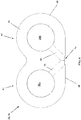
- Traditionally, where the pump includes a pair of intermeshing gears, two separate bearings have been employed, one for each drive shaft on each side of each gear, resulting in a total of four bearings per pump. The general shape of the traditional gear cavity in the housing is similar to a
figure "8 ". Each bearing may have a round portion with a flat side. The flats sides of two bearings are then aligned and installed into the pump housing as a pair, with one pair on each side of the gears.US 5641281 relates to a bearing arrangement for a hydraulic machine having a symmetric gear cavity in the housing similar to afigure "8 " and a corresponding symmetrical bearing assembly.US 3053192 ,US3029739 andEP 0 112 008 A1 relate to other known bearing arrangements. - The traditional bearings may also include features used to help remove trapped fluid from the gear mesh. Often such features are machined on the individual bearing pieces as two separate features. Because the bearing assemblies are made up of so many individual bearing pieces, it is easy for these features to be misaligned during manufacturing and installation. Such misalignment can cause the pump to perform in a less than desired manner. Moreover, the large number of pieces used in the bearing assembly, and the importance of the inter-fitting of the bearing pairs in the bearings into the bearing cavity, makes assembly of the pump very difficult.
- Thus, there is a need for an improved bearing assembly for pumps in general and gear pumps in particular. Such an improved bearing assembly should be easy to install, and should reduce the total number of individual parts required for assembly. The improved bearing assembly should also include features that will reliably enable trapped fluid to be removed from the gear mesh. There is also a need for an improved arrangement that ensures a desired alignment of the components of a gear pump is obtained as the components of the pump are being assembled.
- A bearing and a pump are provided according to
claims 1 and 9, respectively. - By way of example, a specific embodiment of the disclosed device will now be described, with reference to the accompanying drawings:
-
FIG. 1 is a perspective view of a pump including the disclosed bearing; -
FIG. 2 is an exploded view of the pump ofFIG. 1 ; -
FIG. 3 is a cross-section view of the pump ofFIG. 1 taken along line 3-3 ofFIG. 1 ; -
FIG. 4 is detail view of the cross-section view ofFIG. 3 ; -
FIG. 5 is a perspective view of a dual bearing for use in the pump ofFIG. 1 ; -
FIG. 6 is a plan view of the dual bearing ofFIG. 5 ; -
FIG. 7 is a reverse plan view of the dual bearing ofFIG. 5 ; -
FIG. 8 is a cross-section of the dual bearing ofFIG.5 taken along line 8-8 ofFIG. 7 ; -
FIG. 9 is a cross-section of the dual bearing ofFIG.5 taken along line 9-9 ofFIG. 7 ; -
FIG. 10 is an isometric view of a pump according to the disclosure; -
FIG. 11 is an exploded view of the pump ofFIG. 10 ; -
FIG. 12 is a cross-section of the pump ofFIG. 10 taken along line 12-12 ofFIG. 10 ; -
FIG. 13 is a partial detail view of the cross-section view ofFIG. 12 ; -
FIG. 14 is an isometric view of a pump according to the disclosure; -
FIG. 15 is an exploded view of the pump ofFIG. 14 ; -
FIG. 16 is a cross-section of the pump ofFIG. 14 taken along line 16-16 ofFIG. 14 ; -
FIG. 17 is an isometric view of a pump according to the disclosure; -
FIG. 18 is a cross-section of the pump ofFIG. 17 taken along line 18-18 ofFIG. 17 ; -
FIG. 19 is an isometric view of a pump according to the disclosure; -
FIG. 20 is a cross-section of the pump ofFIG. 19 taken along line 20-20 ofFIG. 19 ; -
FIG. 21 is an isometric view of a pump according to the disclosure; and -
FIG. 22 is a cross-section of the pump ofFIG. 21 taken along line 22-22 ofFIG. 21 . - An asymmetrical bearing is disclosed for use in supporting a shaft of a pump. In one embodiment, a single asymmetrical bearing is provided on each side of a pair of gears in a gear pump. The single asymmetrical bearing may support both the drive shaft and the shaft of the driven gear. The asymmetry of the bearing acts to limit the number of degrees of freedom the bearing has during installation. A single bearing can be used on each side of the pump. In addition, the single piece design reduces the total number of parts in the pump, and greatly simplifies the assembly of the pump.
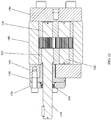
- Referring now to
FIG. 1 , an exemplary gear pump 1 is shown. The gear pump 1 may include acentral gear plate 2, front andrear plates 4, 6, aseal plate 8 and adrive shaft 10. An inlet port (not shown) and anoutlet port 12 may be formed in the central gear plate for moving fluid through the pump 1. The inlet and outlet ports may be coupled to inlet and outlet piping or tubing via an o-ring connection. Thus, thecentral gear plate 2 may include a recess having aflat face portion 13a and first and secondangled surfaces angled surfaces -
FIG. 2 shows the pump 1 in exploded form. As can be seen, thedrive shaft 10 includes afirst gear 18 which intermeshes with asecond gear 20 of a drivenshaft 22. First and secondasymmetrical bearings second gears drive shaft 10 and driveshaft 22 viarespective bores 28A, B, 30A, B. The first andsecond gears asymmetrical bearings asymmetrical opening 32 in thecentral gear plate 2. In the illustrated embodiment, theasymmetrical opening 32 is shaped to correspond to the shape of theasymmetrical bearings - The
seal plate 8 may fix a variety of sealing elements to the front plate 4 to prevent fluid leakage around thedrive shaft 10. The sealing elements may include an o-ring 34, alip seal 36 and a sealingsleeve 38, all of which may be received in a suitably configuredrecess 40 in the front plate 4.FIGS. 3 and4 show the internal inter-relation of components of the pump 1 when assembled. As can be seen, the o-ring 34 is sandwiched between arim portion 40 of the sealingsleeve 38 and ashoulder portion 42 of the front plate 4. Likewise, thelip seal 36 is sandwiched between first andsecond shoulder portions seal plate 8 and afront face 48 of the sealingsleeve 38. Aninner bore 50 of the sealingsleeve 38 includes a plurality ofgrooves 52 for sealing against the surface of therotating drive shaft 10. In some embodiments, thegrooves 52 comprise a helical groove which allows the sealingsleeve 38 to act as a screw-type pump during operation. As fluid attempts to leave the gear pump (around the outer diameter of the drive shaft 10), the shaft's rotary motion forces the fluid into thegroove 52. This creates a pressure greater than the pressure forcing the fluid out of the pump, and forces the fluid back toward thecentral gear plate 2. Thus arranged, the pumped fluid is prevented from leaking past thedrive shaft 10 during operation. -
Pins grooves sleeve 38. The outside diameter of the sealingsleeve 38 is sized to loosely fit within bore 80 of the front plate 4, while the inside diameter of the sealingsleeve 38 is sized to fit closely to theshaft 10. The sealingsleeve 38 is compliantly mounted between the o-ring 34 and thelip seal 36 so that sealingsleeve 38 can always align to theshaft 10. Thus arranged, the pumped fluid is prevented from leaking past thedrive shaft 10 during operation. - Referring now to
FIGS. 5 - 9 , theasymmetrical bearings bearing 26. Thebearing 24 may be a generally flat structure having first and second faces 54, 56 and aside surface 58 that is flat on afirst side 60 and forms a pair oflobes bearing 24 the appearance of the letter "B." - The
first face 54 may include first andsecond grooves first side 60 and which each intersect with one of thebores drive shaft 10 and the drivenshaft 22. Anotch 70 may be provided on thefirst side 60 where thegrooves notch 70 may run from thefirst face 54 to thesecond face 56. The first andsecond grooves 66, 68 (and notch 70) may have any of a variety of cross-sectional shapes and depths, as desired for the particular application. In one embodiment, the grooves are about 0.010 inches deep and about 0.100 inches wide, though this is not critical and the grooves may be of different shapes and depths as desired. For example, the groove width may be about 1/20th of the radius of curvature of one or bothlobes lobes 64. - It will also be appreciated that in alternative embodiments, the grooves could instead be disposed on a portion of the front plate 4. In addition, the
notch 70 could be provided in thegear plate 2 in lieu of thebearing 24. -
FIG. 7 shows that grooves may also be provided in thesecond face 56 of theasymmetrical bearing 24. Thus, athird groove 72 may run between thebores side surface 58 where thelobes bores third groove 72 is offset with respect to the centers of thebores third groove 72 could be angled toward the centers of one or both bores. In one embodiment, the grooves are about 0.010 inches deep and about 0.100 inches wide, though this is not critical and the grooves may be of different shapes and depths as desired. - Each of the
bores lubrication groove 76 in the region in which the bores intersect withthird groove 72. Thislubrication groove 76 may be formed as a portion of acircle 78 that is offset from a center "C" of the respective bore by an offset distance "OD," and at an angle "α" with respect to a line perpendicular to the bearing centerline (represented by section line 8-8). In one embodiment, "α" is about 35 degrees. As can be seen inFIG. 9 , thelubrication groove 76 may further be offset by an angle "β" with respect to a line perpendicular to thesecond face 56 so that thelubrication groove 76 runs from thesecond face 56 to a distance "D" within therespective bore lubrication groove 76 is shown as being tapered, that the groove could instead be machined so that it is not tapered (i.e., β = 0) so that thegroove 76 extends a predefined distance within the bearing bore. - In addition to the above, a small angled transition may be applied to the profile of the entire bearing as well as the profile of the housing or plate where the bearing is installed. These transitions may help allow any angular misalignment to self-correct itself and allow smooth assembly of the bearing in the housing or plate.
- Lubrication of the shafts is always a priority in gear pumps, and the shafts are typically lubricated by fluid being pumped. While many efforts have been made to provide flow paths for the fluid through the bearings, the disclosed design is unique in that one of the features used to help promote fluid flow through the bearings also is used to manufacture the part.
- During manufacturing of the bearing, the piece is held in place with a small amount of excess material. Once machining is finished, the excess material is removed and the
notch 70 is created. Thisnotch 70 functionally serves to fluidly connect the inlet port are withsurface 54, and may act as a return flow path for the fluid used to lubricate the bearings. Thus, in the illustrated embodiment, high pressure fluid is directed along thesecond face 56 of thebearing 24, into a groove in thebores bearing 24, down thefirst face 54 of the bearing to thenotch 70 and finally returns to the low pressure inlet of the pump. As an additional aid in lubrication, an axial groove is created by thelubrication groove 76. It will be appreciated that other methods to convey the fluid to the low pressure inlet may be employed, such as holes in the gear housing plate. - As will be appreciated, the orientation of the asymmetric design is important in promoting fluid flow in the pump. The disclosed asymmetric design creates a cavity on the inlet for the fluid being pumped to collect before being carried around the gear pocket by the gear form. This pool of fluid helps to ensure that the pump does not starve itself during operation and will run at its maximum capacity. The groove 74 is also used to help remove trapped fluid from the gear mesh, extends from a critical dimension off of the centerline of the pump, depending on the gear form, and extends the entire length of the part in a cylindrical fashion.
- Referring now to
FIGS. 10-13 , agear pump 100 will be described that includes features that may result in enhanced alignment of sealing elements and may also facilitate assembly of one or more components of the pump. Thegear pump 100 may be similar to the gear pump 1 described in relation toFIGS. 1-4 . Thus, thepump 100 may include acentral gear plate 102, front andrear plates seal assembly 108 and adrive shaft 110. An inlet port (not shown) and anoutlet port 112 may be formed in the central gear plate for moving fluid through thepump 100. The pump 1 may be fixed in its assembled form via a plurality of fasteners, which in the illustrated embodiment are socket head cap screws 114, 116. -
FIG. 11 shows thepump 100 in exploded form. As can be seen, adrive shaft 110 includes afirst gear 118 which intermeshes with asecond gear 120 of a drivenshaft 122. First and secondasymmetrical bearings second gears drive shaft 110 and drivenshaft 122 viarespective bores 128A, B, 130A, B, respectively. The first andsecond gears asymmetrical bearings asymmetrical opening 132 in thecentral gear plate 102. In the illustrated embodiment, theasymmetrical opening 132 is shaped to correspond to the shape of theasymmetrical bearings asymmetrical bearings bearings FIGS. 5-9 . - The
seal arrangement 108 may include a plurality of sealing elements configured to prevent fluid leakage around thedrive shaft 110. In the illustrated embodiment, the sealingarrangement 108 comprises alip seal housing 134, alip seal 136 and a sealingsleeve 138, which may be fixed together in the stacked relation shown inFIG. 12-13 . Thelip seal 136 may be held in a recess formed in thelip seal housing 134. Acircumferential flange portion 140 of thelip seal 136 may be sandwiched between thelip seal housing 134 and afront surface 142 of the sealingsleeve 138. Thelip seal 136 may form a radial seal around thedrive shaft 110, and may form a face seal between the sealingsleeve 138 and the lip seal housing 134 (the face seal is facilitated by theflange portion 140 of the lip seal 136). - A
cylindrical body portion 144 of the sealingsleeve 138 may be received in anopening 146 of thefront plate 104. In the illustrated embodiment, thedistal end 148 of thecylindrical body portion 144 includes a reduceddiameter portion 150 that is sized to be received within thebore 128A ofasymmetric bearing 124 to align the sealing sleeve within thepump 100. By piloting the sealingsleeve 138 directly off of theasymmetric bearing 124 via a tight fit on the reduceddiameter portion 150 of the sealingsleeve 138,central bore 152 of the sealingsleeve 138 is precisely located relative to theouter diameter 156 of thedriveshaft 110, thus reducing the likelihood for contact between the drive shaft and the sealing sleeve, and also minimizing any eccentricity between the drive shaft and the sealing sleeve. - The sealing
sleeve 138,lip seal 136 andlip seal housing 134 may all have corresponding central bores which receive a portion of thedrive shaft 110 therethrough. Thecentral bore 152 of the sealingsleeve 138 may include ahelical groove 154 which allows the sealing sleeve to act as a screw-type pump during operation, as previously described in relation to the embodiment ofFIGS. 1-4 . - The
pump 100 may further include alignment, or "piloting" features on the sealing elements, thus improving concentricity between the axes of the sealing elements and the axis of the shaft, which are otherwise independent features. As shown, the sealingsleeve 138 includes aflange portion 158 having a forward facingcircumferential alignment recess 160 disposed adjacent to the perimeter of the flange portion. As will be appreciated thisalignment recess 160 can be used to align one or more secondary seals. In the illustrated embodiment, thealignment recess 160 receives a rearward protrudingcircumferential lip portion 162 of thelip seal housing 134. By fitting thecircumferential lip portion 162 into thealignment recess 160, a desired high degree of concentricity between the axis of thedrive shaft 110 and the lip seal axis can be achieved. As shown, thelip seal housing 134 includes itsown alignment recess 164 disposed on a forward facing portion of the housing. Thisalignment recess 164 can be used to align additional sealing elements (not shown), as desired. - During assembly, the sealing
sleeve 138 may be bolted to thefront plate 104. There may be a loose clearance fit between the outer surface of thecylindrical body portion 144 of the sealing sleeve and thefront plate 104. Since the sealing sleeve is not tightly located on thefront plate 104, this loose fit reduces the chances of pump binding during assembly, when thebolts 114 are tightened. The sealingsleeve 138 andlip seal housing 134 can be bolted to thefront plate 104 without thecylindrical body portion 144 of the sealing sleeve touching the through bore in thefront plate 104. The locating feature on the sealing sleeve 138 (i.e., the interaction between the reduceddiameter portion 150 of the sealing sleeve and thebore 128A of asymmetric bearing 124) can be used to align this assembly to the rest of the pump. Thefront plate 104,seal assembly 108 and remainder of the pump components can then be fastened together withfasteners 116. As will be appreciated, the disclosed arrangement can improve sealing performance, and can make pump assembly easier. - Referring now to
FIGS. 14-16 , agear pump 200 will be described that includes a packing seal arrangement for preventing fluid leakage past thedrive shaft 210. Thegear pump 200 of this embodiment may include some or all of the features of the previously describedpumps 1, 100, includingcentral gear plate 202, front andrear plates seal assembly 208 and adrive shaft 210. An inlet port (not shown) and an outlet port 212 may be formed in the central gear plate for moving fluid through thepump 200. Thepump 200 may be fixed in its assembled form via a plurality offasteners pump 200 may also include first and secondasymmetrical bearings drive shaft 210 and a drivenshaft 222. Theasymmetrical bearings bearings FIGS. 5-9 . - The
seal assembly 208 ofpump 200 may comprise a packinghousing 234, packing seals 236A, B and apacking follower 238. This packinghousing 234 has a bore defining an inside diameter "ID" that is larger than the outside diameter "OD" of thedrive shaft 210. The packinghousing 234 may also include arecess 235 formed at a forward end configured to receive a pair of packing seals 236A, B. Therecess 235 may also receive arearwardly projecting portion 237 of thepacking follower 238. As will be understood, therearwardly projecting portion 237 of the packing follower compresses the packing seals 236A, B within therecess 235 to provide a desired sealing engagement with the "OD" of thedrive shaft 210. Compression of the packing seals 236A, B can be adjusted viafasteners 215. - A
cylindrical body portion 244 of the packinghousing 234 may be received in anopening 246 of thefront plate 204. In the illustrated embodiment, adistal end 248 of thecylindrical body portion 244 includes a reduceddiameter portion 250 that is sized to be received within thebore 228A ofasymmetric bearing 224 to align the packinghousing 234 within thepump 200. By piloting the packinghousing 234 directly off of theasymmetric bearing 224 via a tight fit on the reduceddiameter portion 250 of the packinghousing 234, the "ID" of the packinghousing 234 is precisely located relative to the outer diameter "OD" of thedriveshaft 210, thus reducing the likelihood for contact between the drive shaft and the packing housing, and also minimizing any eccentricity between the drive shaft and the packing housing. - In the illustrated embodiment, the packing
housing 234 also includes analignment recess 264 disposed on a forward facing portion of the housing. Thisalignment recess 264 can be used to align additional sealing elements (not shown), as desired. In addition, the disclosed design can be modular in that additional packing rings with an additional packing housing can be included. -
FIGS. 17-18 show agear pump 300 that is similar to thepump 100 described in relation toFIGS. 10-13 . Thegear pump 300 of this embodiment, however, has aseal assembly 308 that includes a pair oflip seal housings 338A, B and a pair of lip seals 336A, B, in addition to the sealingsleeve 334. The sealingsleeve 334 of this embodiment may include any or all of the features of the sealing sleeve described in relation toFIGS. 10-13 . - The embodiment of
FIGS. 17-18 illustrates that the disclosed aligning features (circumferential alignment recesses 360A, 360B in the sealingsleeve 334 and thelip seal housing 338A engagingcircumferential lip portions lip seal housings 338A, B) can be employed to add additional sealing options to the basic sealing configuration shown inFIGS. 10-13 , thus exemplifying how the seal design can be modular, or configurable. - In this embodiment, the sealing
sleeve 334 is aligned via theasymmetrical bearing 324 in the same manner as described in relation to the embodiment ofFIGS. 10- 13 (i.e., via reduceddiameter portion 350 received in the bore328A of the bearing 324). The firstlip seal housing 338A piloted off the sealing sleeve 334 (i.e., via the interengagement ofrecess 360A andlip 362A), while the secondlip seal housing 338B is piloted off of the firstlip seal housing 338A (i.e., via the interengagement ofrecess 360B andlip 362B). As can be seen, the first and secondlip seal housings 338A, B receive the first and second lip seals 336A, B, respectively, resulting in a pair of face seals. As will be appreciated, this arrangement allows the sealingsleeve 334 and both lip seals 336A, B to be precisely aligned to thedrive shaft 310. As will also be appreciated, additional lip seal housings and lip seals can be added as desired. For this purposed, the secondlip seal housing 338B includes acircumferential alignment groove 360C on a forward face thereof. -
FIGS. 19-20 show agear pump 400 that is similar to the previously described pumps, but which includes aseal assembly 408 that is a hybrid of the sealing sleeve and the packing seal designs. Specifically, theseal assembly 408 includes a sealingsleeve 438, a pair of packing rings 436A, B and apacking follower 434. The sealingsleeve 438 of this embodiment may include any or all of the features of the sealing sleeve described in relation toFIGS. 10-13 . In addition, the sealingsleeve 438 includes arecess 435 for receiving the packing rings 436A, B. Thus, the sealingsleeve 438 acts as a packing housing. Therecess 435 may also receive arearwardly projecting portion 437 of thepacking follower 434. As will be understood, therearwardly projecting portion 437 of the packing follower compresses the packing seals 436A, B within therecess 435 to provide a desired sealing engagement with thedrive shaft 410. Compression of the packing seals 436A, B can be adjusted viafasteners 415. - Thus arranged, the sealing
sleeve 438 is aligned by thebore 428A of theasymmetric bearing 424 in the manner previously described in relation toFIGS. 13 and18 . The packing seals 436A, B are installed and aligned within therecess 435 in the sealing sleeve so that they are concentric to thedrive shaft 410. Thepacking follower 434 is then bolted to the sealingsleeve 438. In this embodiment, the sealingsleeve 438 also includes anexternal alignment groove 460 which can be used to add another packing housing and additional packing rings, if desired. -
FIGS. 21-22 show yet another option for the disclosed modular seal design. Thepump 500 of this embodiment incorporates aseal assembly 508 that includes aflush plate 537 in combination with alip seal housing 538, alip seal 536, and aRheoseal 534. Thelip seal housing 538,lip seal 536, and sealingsleeve 534 can all include the features described in relation to previous embodiments. - As will be appreciated, the
flush plate 537 can be used to flush out the inside of thelip seal 536 and any fluid that may escape between the drive shaft 510 and the sealingsleeve 534. In one embodiment, flush fluid is introduced through aport 539, filling acavity 541 around the drive shaft 510 and inside thelip seal 536. The flush fluid may be discharged through another port (not shown) in theflush plate 537. - The
lip seal housing 538,flush plate 537, and sealingsleeve 534 may all be aligned in thepump 500 in a manner previously described. Thus, the sealingsleeve 534 may be piloted to thebore 528A of theasymmetrical bearing 524 in the manner previously described in relation to the embodiment ofFIG. 13 . Theflush plate 537 may have a rearwardly facingcircumferential lip portion 562A that is received in a complementary alignment recess 560A formed in a forward face of the sealingsleeve 534. Thelip seal housing 538, likewise, may have a rearwardly facingcircumferential lip portion 562B that is received in acomplementary alignment recess 560B formed in a forward face of theflush plate 537. Thelip seal 536 may be held within a recess in thelip seal housing 538 in the manner previously described in relation to other embodiments. Thelip seal housing 538 may also include acircumferential alignment recess 360C formed in a forward face thereof so that additional sealing components can be added and aligned. Thus arranged, concentricity between thelip seal 536, sealingsleeve 534 and the drive shaft 510 is maintained.
Claims (13)
- A bearing, comprising:first and second opposing faces (54, 56);first and second bores (28A,B, 128A,B) in communication with the first and second opposing faces (54, 56), the first and second bores (28A,B, 128 A,B) configured to receive first and second shafts;a first flat side surface (60) and a second curved side surface, the second curved side surface having first and second curved portions associated with the first and second bores, respectively; anda plurality of grooves (66, 68) in the first and second opposing faces and the first flat side surface wherein,the bearing (24, 26, 124, 126, 224, 226) is asymmetrical; andthe plurality of grooves (66, 68) extending from the first flat side surface to the first and second bores (28A,B, 128A,B) are configured to direct a flow of process fluid over the bearing during operation of the bearing and characterized in that
the plurality of grooves in the first face includes first and second grooves (66, 68) that run from a common position on the first flat side surface (60) and each one of which intersects with one of the bores (28A, 28B); anda notch (70) is provided on the first flat side surface (60) where the first and second grooves (66, 68) meet, and in that the notch (70) runs from the first face (54) to the second face (56). - The bearing of claim 1, wherein the first and second bores (28A,28B) of the asymmetrical bearing (24,26,124,126) further include a lubrication groove (76).
- The bearing of claim 2, wherein the lubrication groove (76) is formed as a portion of a circle (78) that is offset from a center of the respective bore by an offset distance, and at an angle "α" with respect to a line perpendicular to the bearing centerline.
- The bearing of claim 2, wherein the lubrication groove (76) is offset by an angle "β" with respect to a line perpendicular to the second opposing face (56) of the bearing so that the lubrication groove (76) runs from the second face to a distance "D" within the first and second bores.
- The bearing of claim 2, wherein the lubrication groove (76) is perpendicular to the second opposing face (56) of the bearing and runs from the second face (56) to a distance "D" within the bore.
- The bearing of claim 1, wherein the plurality of grooves (66, 68) include first and second grooves disposed in the first opposing face and third and fourth grooves disposed in the second opposing face (56), the first and second grooves (66, 68) oriented at an oblique angle with respect to each other, and the third and fourth grooves oriented at an oblique angle with respect to each other.
- The bearing of claim 6, wherein the first, second, third and fourth grooves intersect with a fifth groove in the first flat side surface.
- The bearing of claim 1, wherein the plurality of grooves include first and second grooves disposed in the first opposing face and third and fourth grooves (72, 74) disposed in the second opposing face, the first and second grooves oriented perpendicular to each other, and the third and fourth (72, 74) grooves oriented perpendicular to each other.
- A pump (1, 100, 200, 300, 400, 500), comprising:a housing;a drive shaft (10, 110, 210, 310, 410, 510) as a first shaft having a first gear (18, 118); anda driven shaft (22, 122, 222) as a second shaft having a second gear (20, 120); and having a first and a second bearing (24, 26, 124, 126, 224, 226, 324, 424, 524) according to any of claims 1 to 8.
- The pump of claim 9, further comprising a seal assembly (108, 208, 408, 508) comprising first and second sealing elements (38, 138, 334, 438, 534, 36, 134, 338A, 538), the first and second sealing elements (38, 138, 334, 438, 534, 36, 134, 338A, 538) including corresponding alignment features that interengage with each other to result in a desired alignment of the first and second sealing elements (38, 138, 334, 438, 534, 36, 134, 338A, 538) with the drive shaft when the pump (1, 100, 200, 300, 400, 500) is assembled.
- The pump of claim 10, wherein a distal end of the first sealing element is received within the first or second bore of the first or second asymmetrical bearing (24, 26, 124, 126, 224, 226).
- The pump of claim 11, wherein the first sealing element is a sealing sleeve (138, 334, 534), and the second sealing element is a lip seal housing (134, 338A, 538) containing a lip seal (136, 336A, 536), the lip seal (136, 336A, 536) providing a face sealing feature via engagement with the sealing sleeve (138, 334, 534) and a shaft sealing feature via engagement with the drive shaft.
- The pump of claim 12, further comprising a flush plate (537) disposed between the sealing sleeve (534) and a lip seal housing (538), the flush plate (537) including a flush port for introducing fluid to an outer portion of the drive shaft (510) and to an inner portion of the lip seal (536), the flush plate further comprising a circumferential lip (562A) configured to be received in a circumferential recess (560A) of the sealing sleeve, and a circumferential recess (560B) configured to receive a circumferential lip (562B) of the lip seal housing.
Applications Claiming Priority (3)
| Application Number | Priority Date | Filing Date | Title |
|---|---|---|---|
| US201261618218P | 2012-03-30 | 2012-03-30 | |
| US13/850,884 US8998496B2 (en) | 2012-03-30 | 2013-03-26 | Gear pump with asymmetrical dual bearing |
| PCT/US2013/034034 WO2013148792A1 (en) | 2012-03-30 | 2013-03-27 | Gear pump with asymmetrical dual bearing |
Publications (3)
| Publication Number | Publication Date |
|---|---|
| EP2831435A1 EP2831435A1 (en) | 2015-02-04 |
| EP2831435A4 EP2831435A4 (en) | 2015-09-23 |
| EP2831435B1 true EP2831435B1 (en) | 2020-04-22 |
Family
ID=49235299
Family Applications (1)
| Application Number | Title | Priority Date | Filing Date |
|---|---|---|---|
| EP13767455.2A Active EP2831435B1 (en) | 2012-03-30 | 2013-03-27 | Gear pump with asymmetrical dual bearing |
Country Status (7)
| Country | Link |
|---|---|
| US (1) | US8998496B2 (en) |
| EP (1) | EP2831435B1 (en) |
| JP (1) | JP6033398B2 (en) |
| CN (1) | CN104395625B (en) |
| IN (1) | IN2014MN02167A (en) |
| WO (1) | WO2013148792A1 (en) |
| ZA (1) | ZA201407119B (en) |
Families Citing this family (15)
| Publication number | Priority date | Publication date | Assignee | Title |
|---|---|---|---|---|
| US10323636B2 (en) | 2014-03-21 | 2019-06-18 | Circor Pumps North America, Llc | Gear pump with end plates or bearings having spiral grooves |
| WO2015168220A1 (en) * | 2014-05-01 | 2015-11-05 | Imo Industries, Inc. | Pump with shaped face seal |
| WO2015179042A1 (en) * | 2014-05-21 | 2015-11-26 | Imo Industries, Inc. | A gear pump having through-shaft bearing weepage control |
| US9488170B2 (en) * | 2014-06-06 | 2016-11-08 | Hamilton Sundstrand Corporation | Gear pump driven gear pressure loaded bearing |
| CN104533785A (en) * | 2014-12-24 | 2015-04-22 | 苏州工业园区华西泵业有限公司 | Chemical fibre pump and sealing method thereof |
| JP6492872B2 (en) * | 2015-03-30 | 2019-04-03 | ブラザー工業株式会社 | Adhesive supply device and cloth bonding device |
| DE102015221338A1 (en) * | 2015-10-30 | 2017-05-04 | Robert Bosch Gmbh | External gear pump for a waste heat recovery system |
| JP6616663B2 (en) * | 2015-11-05 | 2019-12-04 | 住友ゴム工業株式会社 | Gear pump equipment for rubber extrusion |
| KR101698726B1 (en) * | 2016-07-25 | 2017-01-20 | 심만섭 | Rotary gear pump |
| DE102016225826A1 (en) * | 2016-12-21 | 2018-06-21 | Robert Bosch Gmbh | External gear unit |
| CN108035876A (en) * | 2017-12-08 | 2018-05-15 | 镇江沃尔夫重工部件有限公司 | It is a kind of that there is the gear pump got express developed |
| JP2019190401A (en) * | 2018-04-26 | 2019-10-31 | 宇部興産株式会社 | Gear pump |
| US11821421B2 (en) * | 2019-06-11 | 2023-11-21 | PSI-Polymer Systems, Inc. | Gear pumps used in fluid processing lines and seal systems for fluid processing apparatuses |
| US10962059B2 (en) | 2019-06-17 | 2021-03-30 | Hamilton Sundstrand Corporation | Bearing with an eccentric seal groove |
| US10858940B1 (en) | 2019-06-17 | 2020-12-08 | Hamilton Sundstrand Corporation | Bearing with an asymmetric pressure balance groove |
Citations (2)
| Publication number | Priority date | Publication date | Assignee | Title |
|---|---|---|---|---|
| US3029739A (en) * | 1958-07-09 | 1962-04-17 | John L Nagely | Gear pump or motor with radial pressure balancing means |
| EP0112008A1 (en) * | 1982-11-25 | 1984-06-27 | Plessey Overseas Limited | A pressure loaded gear pump |
Family Cites Families (15)
| Publication number | Priority date | Publication date | Assignee | Title |
|---|---|---|---|---|
| US3053192A (en) * | 1960-03-01 | 1962-09-11 | Bosch Gmbh Robert | Bearing arrangement for a hydraulic machine |
| GB1232590A (en) * | 1967-08-21 | 1971-05-19 | ||
| FR2033502A5 (en) | 1969-02-26 | 1970-12-04 | Hydroperfect Internal | |
| US3833319A (en) * | 1973-03-21 | 1974-09-03 | Dowty Hydraulic Units Ltd | Positive-displacement liquid-pressure machines and pressure-balanced journal/thrust bushes therefor |
| DE8806388U1 (en) * | 1987-09-10 | 1989-01-12 | Robert Bosch Gmbh, 7000 Stuttgart, De | |
| JPH0727427Y2 (en) * | 1989-10-31 | 1995-06-21 | 株式会社島津製作所 | Gear pump |
| JP2539194Y2 (en) * | 1993-03-18 | 1997-06-25 | オンキヨー株式会社 | Gear pump bearing structure |
| US5417556A (en) | 1994-03-08 | 1995-05-23 | Alliedsignal Inc. | Bearing for gear pump |
| US5641281A (en) * | 1995-11-20 | 1997-06-24 | Lci Corporation | Lubricating means for a gear pump |
| US5702234A (en) | 1995-12-01 | 1997-12-30 | Micropump, Inc. | Fluid pump with bearing set having lubrication path |
| JPH1193792A (en) * | 1997-09-18 | 1999-04-06 | Hitachi Ltd | Fuel supply device and fuel pump for vehicle engine |
| US6213745B1 (en) * | 1999-05-03 | 2001-04-10 | Dynisco | High-pressure, self-lubricating journal bearings |
| GB0114434D0 (en) | 2001-06-14 | 2001-08-08 | Lucas Industries Ltd | Bearing arrangement |
| EP1988290B2 (en) * | 2006-02-20 | 2019-09-11 | Shimadzu Mectem, Inc. | Gear pump |
| CN201335011Y (en) * | 2008-12-18 | 2009-10-28 | 四川长江液压件有限责任公司 | Floating side plate for high-pressure gear pump |
-
2013
- 2013-03-26 US US13/850,884 patent/US8998496B2/en active Active
- 2013-03-27 EP EP13767455.2A patent/EP2831435B1/en active Active
- 2013-03-27 CN CN201380027008.0A patent/CN104395625B/en active Active
- 2013-03-27 IN IN2167MUN2014 patent/IN2014MN02167A/en unknown
- 2013-03-27 WO PCT/US2013/034034 patent/WO2013148792A1/en active Application Filing
- 2013-03-27 JP JP2015503504A patent/JP6033398B2/en active Active
-
2014
- 2014-10-01 ZA ZA2014/07119A patent/ZA201407119B/en unknown
Patent Citations (2)
| Publication number | Priority date | Publication date | Assignee | Title |
|---|---|---|---|---|
| US3029739A (en) * | 1958-07-09 | 1962-04-17 | John L Nagely | Gear pump or motor with radial pressure balancing means |
| EP0112008A1 (en) * | 1982-11-25 | 1984-06-27 | Plessey Overseas Limited | A pressure loaded gear pump |
Also Published As
| Publication number | Publication date |
|---|---|
| EP2831435A4 (en) | 2015-09-23 |
| EP2831435A1 (en) | 2015-02-04 |
| US20130259729A1 (en) | 2013-10-03 |
| ZA201407119B (en) | 2015-12-23 |
| JP6033398B2 (en) | 2016-11-30 |
| US8998496B2 (en) | 2015-04-07 |
| WO2013148792A1 (en) | 2013-10-03 |
| IN2014MN02167A (en) | 2015-08-28 |
| JP2015518538A (en) | 2015-07-02 |
| CN104395625A (en) | 2015-03-04 |
| CN104395625B (en) | 2016-12-28 |
Similar Documents
| Publication | Publication Date | Title |
|---|---|---|
| EP2831435B1 (en) | Gear pump with asymmetrical dual bearing | |
| EP1540184B1 (en) | Gear pump | |
| JP2021021398A (en) | Pump, and method of transferring fluid from first port to second port of pump | |
| US7481633B2 (en) | Rotor with cut-outs | |
| JPH07259874A (en) | Universal shaft coupling particulay mounted on universal coupling shaft for helical rotor machine | |
| JP5904961B2 (en) | Screw compressor | |
| EP2669522A1 (en) | Single-shaft eccentric screw pump | |
| EP2035708B1 (en) | Moineau pump | |
| JP5917536B2 (en) | Fluid device with pressure roller pocket | |
| JP2017137824A (en) | Screw pump | |
| KR20140106581A (en) | Internal-gear pump | |
| EP3904687B1 (en) | Gear pump | |
| EP3828415B1 (en) | Internal gear pump | |
| JP5721521B2 (en) | Internal gear type oil pump | |
| CN106609753A (en) | Fusion rotor type oil pump and motor | |
| CN115711212A (en) | Compact type duplex variable plunger pump | |
| KR101948228B1 (en) | Gerotor pump having separation plate integrated with housing | |
| CN103384752B (en) | For the balance board set of fluid means | |
| US6716011B2 (en) | Hydraulic pump utilizing floating shafts | |
| CN100572813C (en) | Pin-hole type cycloid rotor pump | |
| JPS60230581A (en) | Immersion motor rotor pump | |
| RU2143592C1 (en) | Centrifugal gear pump | |
| JP2016138521A (en) | Screw compressor | |
| JP4895187B2 (en) | Internal gear pump | |
| CN103306971B (en) | internal gear pump |
Legal Events
| Date | Code | Title | Description |
|---|---|---|---|
| PUAI | Public reference made under article 153(3) epc to a published international application that has entered the european phase |
Free format text: ORIGINAL CODE: 0009012 |
|
| 17P | Request for examination filed |
Effective date: 20141023 |
|
| AK | Designated contracting states |
Kind code of ref document: A1 Designated state(s): AL AT BE BG CH CY CZ DE DK EE ES FI FR GB GR HR HU IE IS IT LI LT LU LV MC MK MT NL NO PL PT RO RS SE SI SK SM TR |
|
| AX | Request for extension of the european patent |
Extension state: BA ME |
|
| DAX | Request for extension of the european patent (deleted) | ||
| RA4 | Supplementary search report drawn up and despatched (corrected) |
Effective date: 20150820 |
|
| RIC1 | Information provided on ipc code assigned before grant |
Ipc: F16C 33/10 20060101AFI20150814BHEP |
|
| STAA | Information on the status of an ep patent application or granted ep patent |
Free format text: STATUS: EXAMINATION IS IN PROGRESS |
|
| 17Q | First examination report despatched |
Effective date: 20180404 |
|
| RAP1 | Party data changed (applicant data changed or rights of an application transferred) |
Owner name: CIRCOR PUMPS NORTH AMERICA, LLC |
|
| GRAP | Despatch of communication of intention to grant a patent |
Free format text: ORIGINAL CODE: EPIDOSNIGR1 |
|
| STAA | Information on the status of an ep patent application or granted ep patent |
Free format text: STATUS: GRANT OF PATENT IS INTENDED |
|
| INTG | Intention to grant announced |
Effective date: 20191104 |
|
| GRAS | Grant fee paid |
Free format text: ORIGINAL CODE: EPIDOSNIGR3 |
|
| GRAJ | Information related to disapproval of communication of intention to grant by the applicant or resumption of examination proceedings by the epo deleted |
Free format text: ORIGINAL CODE: EPIDOSDIGR1 |
|
| GRAL | Information related to payment of fee for publishing/printing deleted |
Free format text: ORIGINAL CODE: EPIDOSDIGR3 |
|
| STAA | Information on the status of an ep patent application or granted ep patent |
Free format text: STATUS: EXAMINATION IS IN PROGRESS |
|
| GRAR | Information related to intention to grant a patent recorded |
Free format text: ORIGINAL CODE: EPIDOSNIGR71 |
|
| STAA | Information on the status of an ep patent application or granted ep patent |
Free format text: STATUS: GRANT OF PATENT IS INTENDED |
|
| GRAA | (expected) grant |
Free format text: ORIGINAL CODE: 0009210 |
|
| STAA | Information on the status of an ep patent application or granted ep patent |
Free format text: STATUS: THE PATENT HAS BEEN GRANTED |
|
| INTC | Intention to grant announced (deleted) | ||
| AK | Designated contracting states |
Kind code of ref document: B1 Designated state(s): AL AT BE BG CH CY CZ DE DK EE ES FI FR GB GR HR HU IE IS IT LI LT LU LV MC MK MT NL NO PL PT RO RS SE SI SK SM TR |
|
| INTG | Intention to grant announced |
Effective date: 20200317 |
|
| REG | Reference to a national code |
Ref country code: GB Ref legal event code: FG4D |
|
| REG | Reference to a national code |
Ref country code: CH Ref legal event code: EP |
|
| REG | Reference to a national code |
Ref country code: IE Ref legal event code: FG4D |
|
| REG | Reference to a national code |
Ref country code: DE Ref legal event code: R096 Ref document number: 602013068181 Country of ref document: DE |
|
| REG | Reference to a national code |
Ref country code: AT Ref legal event code: REF Ref document number: 1260509 Country of ref document: AT Kind code of ref document: T Effective date: 20200515 |
|
| REG | Reference to a national code |
Ref country code: LT Ref legal event code: MG4D |
|
| REG | Reference to a national code |
Ref country code: NL Ref legal event code: MP Effective date: 20200422 |
|
| PG25 | Lapsed in a contracting state [announced via postgrant information from national office to epo] |
Ref country code: LT Free format text: LAPSE BECAUSE OF FAILURE TO SUBMIT A TRANSLATION OF THE DESCRIPTION OR TO PAY THE FEE WITHIN THE PRESCRIBED TIME-LIMIT Effective date: 20200422 Ref country code: NL Free format text: LAPSE BECAUSE OF FAILURE TO SUBMIT A TRANSLATION OF THE DESCRIPTION OR TO PAY THE FEE WITHIN THE PRESCRIBED TIME-LIMIT Effective date: 20200422 Ref country code: NO Free format text: LAPSE BECAUSE OF FAILURE TO SUBMIT A TRANSLATION OF THE DESCRIPTION OR TO PAY THE FEE WITHIN THE PRESCRIBED TIME-LIMIT Effective date: 20200722 Ref country code: SE Free format text: LAPSE BECAUSE OF FAILURE TO SUBMIT A TRANSLATION OF THE DESCRIPTION OR TO PAY THE FEE WITHIN THE PRESCRIBED TIME-LIMIT Effective date: 20200422 Ref country code: PT Free format text: LAPSE BECAUSE OF FAILURE TO SUBMIT A TRANSLATION OF THE DESCRIPTION OR TO PAY THE FEE WITHIN THE PRESCRIBED TIME-LIMIT Effective date: 20200824 Ref country code: GR Free format text: LAPSE BECAUSE OF FAILURE TO SUBMIT A TRANSLATION OF THE DESCRIPTION OR TO PAY THE FEE WITHIN THE PRESCRIBED TIME-LIMIT Effective date: 20200723 Ref country code: IS Free format text: LAPSE BECAUSE OF FAILURE TO SUBMIT A TRANSLATION OF THE DESCRIPTION OR TO PAY THE FEE WITHIN THE PRESCRIBED TIME-LIMIT Effective date: 20200822 Ref country code: FI Free format text: LAPSE BECAUSE OF FAILURE TO SUBMIT A TRANSLATION OF THE DESCRIPTION OR TO PAY THE FEE WITHIN THE PRESCRIBED TIME-LIMIT Effective date: 20200422 |
|
| REG | Reference to a national code |
Ref country code: AT Ref legal event code: MK05 Ref document number: 1260509 Country of ref document: AT Kind code of ref document: T Effective date: 20200422 |
|
| PG25 | Lapsed in a contracting state [announced via postgrant information from national office to epo] |
Ref country code: HR Free format text: LAPSE BECAUSE OF FAILURE TO SUBMIT A TRANSLATION OF THE DESCRIPTION OR TO PAY THE FEE WITHIN THE PRESCRIBED TIME-LIMIT Effective date: 20200422 Ref country code: RS Free format text: LAPSE BECAUSE OF FAILURE TO SUBMIT A TRANSLATION OF THE DESCRIPTION OR TO PAY THE FEE WITHIN THE PRESCRIBED TIME-LIMIT Effective date: 20200422 Ref country code: LV Free format text: LAPSE BECAUSE OF FAILURE TO SUBMIT A TRANSLATION OF THE DESCRIPTION OR TO PAY THE FEE WITHIN THE PRESCRIBED TIME-LIMIT Effective date: 20200422 Ref country code: BG Free format text: LAPSE BECAUSE OF FAILURE TO SUBMIT A TRANSLATION OF THE DESCRIPTION OR TO PAY THE FEE WITHIN THE PRESCRIBED TIME-LIMIT Effective date: 20200722 |
|
| PG25 | Lapsed in a contracting state [announced via postgrant information from national office to epo] |
Ref country code: AL Free format text: LAPSE BECAUSE OF FAILURE TO SUBMIT A TRANSLATION OF THE DESCRIPTION OR TO PAY THE FEE WITHIN THE PRESCRIBED TIME-LIMIT Effective date: 20200422 |
|
| REG | Reference to a national code |
Ref country code: DE Ref legal event code: R097 Ref document number: 602013068181 Country of ref document: DE |
|
| PG25 | Lapsed in a contracting state [announced via postgrant information from national office to epo] |
Ref country code: ES Free format text: LAPSE BECAUSE OF FAILURE TO SUBMIT A TRANSLATION OF THE DESCRIPTION OR TO PAY THE FEE WITHIN THE PRESCRIBED TIME-LIMIT Effective date: 20200422 Ref country code: CZ Free format text: LAPSE BECAUSE OF FAILURE TO SUBMIT A TRANSLATION OF THE DESCRIPTION OR TO PAY THE FEE WITHIN THE PRESCRIBED TIME-LIMIT Effective date: 20200422 Ref country code: DK Free format text: LAPSE BECAUSE OF FAILURE TO SUBMIT A TRANSLATION OF THE DESCRIPTION OR TO PAY THE FEE WITHIN THE PRESCRIBED TIME-LIMIT Effective date: 20200422 Ref country code: RO Free format text: LAPSE BECAUSE OF FAILURE TO SUBMIT A TRANSLATION OF THE DESCRIPTION OR TO PAY THE FEE WITHIN THE PRESCRIBED TIME-LIMIT Effective date: 20200422 Ref country code: SM Free format text: LAPSE BECAUSE OF FAILURE TO SUBMIT A TRANSLATION OF THE DESCRIPTION OR TO PAY THE FEE WITHIN THE PRESCRIBED TIME-LIMIT Effective date: 20200422 Ref country code: IT Free format text: LAPSE BECAUSE OF FAILURE TO SUBMIT A TRANSLATION OF THE DESCRIPTION OR TO PAY THE FEE WITHIN THE PRESCRIBED TIME-LIMIT Effective date: 20200422 Ref country code: AT Free format text: LAPSE BECAUSE OF FAILURE TO SUBMIT A TRANSLATION OF THE DESCRIPTION OR TO PAY THE FEE WITHIN THE PRESCRIBED TIME-LIMIT Effective date: 20200422 Ref country code: EE Free format text: LAPSE BECAUSE OF FAILURE TO SUBMIT A TRANSLATION OF THE DESCRIPTION OR TO PAY THE FEE WITHIN THE PRESCRIBED TIME-LIMIT Effective date: 20200422 |
|
| PG25 | Lapsed in a contracting state [announced via postgrant information from national office to epo] |
Ref country code: PL Free format text: LAPSE BECAUSE OF FAILURE TO SUBMIT A TRANSLATION OF THE DESCRIPTION OR TO PAY THE FEE WITHIN THE PRESCRIBED TIME-LIMIT Effective date: 20200422 Ref country code: SK Free format text: LAPSE BECAUSE OF FAILURE TO SUBMIT A TRANSLATION OF THE DESCRIPTION OR TO PAY THE FEE WITHIN THE PRESCRIBED TIME-LIMIT Effective date: 20200422 |
|
| PLBE | No opposition filed within time limit |
Free format text: ORIGINAL CODE: 0009261 |
|
| STAA | Information on the status of an ep patent application or granted ep patent |
Free format text: STATUS: NO OPPOSITION FILED WITHIN TIME LIMIT |
|
| 26N | No opposition filed |
Effective date: 20210125 |
|
| REG | Reference to a national code |
Ref country code: CH Ref legal event code: NV Representative=s name: VALIPAT S.A. C/O BOVARD SA NEUCHATEL, CH |
|
| PG25 | Lapsed in a contracting state [announced via postgrant information from national office to epo] |
Ref country code: SI Free format text: LAPSE BECAUSE OF FAILURE TO SUBMIT A TRANSLATION OF THE DESCRIPTION OR TO PAY THE FEE WITHIN THE PRESCRIBED TIME-LIMIT Effective date: 20200422 |
|
| PG25 | Lapsed in a contracting state [announced via postgrant information from national office to epo] |
Ref country code: MC Free format text: LAPSE BECAUSE OF FAILURE TO SUBMIT A TRANSLATION OF THE DESCRIPTION OR TO PAY THE FEE WITHIN THE PRESCRIBED TIME-LIMIT Effective date: 20200422 |
|
| REG | Reference to a national code |
Ref country code: BE Ref legal event code: MM Effective date: 20210331 |
|
| PG25 | Lapsed in a contracting state [announced via postgrant information from national office to epo] |
Ref country code: FR Free format text: LAPSE BECAUSE OF NON-PAYMENT OF DUE FEES Effective date: 20210331 Ref country code: LU Free format text: LAPSE BECAUSE OF NON-PAYMENT OF DUE FEES Effective date: 20210327 |
|
| PG25 | Lapsed in a contracting state [announced via postgrant information from national office to epo] |
Ref country code: BE Free format text: LAPSE BECAUSE OF NON-PAYMENT OF DUE FEES Effective date: 20210331 |
|
| PGFP | Annual fee paid to national office [announced via postgrant information from national office to epo] |
Ref country code: IE Payment date: 20230209 Year of fee payment: 11 |
|
| PG25 | Lapsed in a contracting state [announced via postgrant information from national office to epo] |
Ref country code: HU Free format text: LAPSE BECAUSE OF FAILURE TO SUBMIT A TRANSLATION OF THE DESCRIPTION OR TO PAY THE FEE WITHIN THE PRESCRIBED TIME-LIMIT; INVALID AB INITIO Effective date: 20130327 |
|
| PGFP | Annual fee paid to national office [announced via postgrant information from national office to epo] |
Ref country code: GB Payment date: 20230202 Year of fee payment: 11 Ref country code: DE Payment date: 20230131 Year of fee payment: 11 |
|
| P01 | Opt-out of the competence of the unified patent court (upc) registered |
Effective date: 20230512 |
|
| PG25 | Lapsed in a contracting state [announced via postgrant information from national office to epo] |
Ref country code: CY Free format text: LAPSE BECAUSE OF FAILURE TO SUBMIT A TRANSLATION OF THE DESCRIPTION OR TO PAY THE FEE WITHIN THE PRESCRIBED TIME-LIMIT Effective date: 20200422 |
|
| PGFP | Annual fee paid to national office [announced via postgrant information from national office to epo] |
Ref country code: CH Payment date: 20230401 Year of fee payment: 11 |