EP1266601A2 - Deflector arrangements - Google Patents
Deflector arrangements Download PDFInfo
- Publication number
- EP1266601A2 EP1266601A2 EP02254119A EP02254119A EP1266601A2 EP 1266601 A2 EP1266601 A2 EP 1266601A2 EP 02254119 A EP02254119 A EP 02254119A EP 02254119 A EP02254119 A EP 02254119A EP 1266601 A2 EP1266601 A2 EP 1266601A2
- Authority
- EP
- European Patent Office
- Prior art keywords
- deflector
- toilet
- arrangement according
- deflector arrangement
- arrangement
- Prior art date
- Legal status (The legal status is an assumption and is not a legal conclusion. Google has not performed a legal analysis and makes no representation as to the accuracy of the status listed.)
- Withdrawn
Links
Images


Classifications
-
- A—HUMAN NECESSITIES
- A47—FURNITURE; DOMESTIC ARTICLES OR APPLIANCES; COFFEE MILLS; SPICE MILLS; SUCTION CLEANERS IN GENERAL
- A47K—SANITARY EQUIPMENT NOT OTHERWISE PROVIDED FOR; TOILET ACCESSORIES
- A47K13/00—Seats or covers for all kinds of closets
- A47K13/24—Parts or details not covered in, or of interest apart from, groups A47K13/02 - A47K13/22, e.g. devices imparting a swinging or vibrating motion to the seats
-
- Y—GENERAL TAGGING OF NEW TECHNOLOGICAL DEVELOPMENTS; GENERAL TAGGING OF CROSS-SECTIONAL TECHNOLOGIES SPANNING OVER SEVERAL SECTIONS OF THE IPC; TECHNICAL SUBJECTS COVERED BY FORMER USPC CROSS-REFERENCE ART COLLECTIONS [XRACs] AND DIGESTS
- Y10—TECHNICAL SUBJECTS COVERED BY FORMER USPC
- Y10S—TECHNICAL SUBJECTS COVERED BY FORMER USPC CROSS-REFERENCE ART COLLECTIONS [XRACs] AND DIGESTS
- Y10S4/00—Baths, closets, sinks, and spittoons
- Y10S4/05—Urine guards
Abstract
Description
- The present invention relates to deflector arrangements and particularly but not exclusively to deflector arrangements for deflecting a stream of urine in to a toilet.
- When males sit on a toilet for use, which is often a necessity for elderly, infirm or disabled males, occasionally urine is accidentally directed over the front of the toilet. This soils the area around the toilet presenting problems of hygiene and moreover a cause for embarrassment to the male concerned.
- According to the present invention there is provided a deflector arrangement comprising a deflector and means to attach the deflector to a toilet and enable the deflector to be selectively moved to and from an operable position in which the deflector can deflect urine into the toilet.
- Preferably the means enables the deflector to be moved between said operable position and one or more further position(s) in which the deflector presents no or substantially no obstacle to a user of the toilet, particularly when the user is getting on and off the toilet.
- Preferably the deflector is located generally at the front of the toilet when in the operable position, and desirably generally centrally whereby to locate between the legs of a person sitting on the toilet.
- Preferably the deflector is located generally beneath the seating area of a toilet, and preferably is on the outside of the toilet when in the said further position(s).
- The deflector preferably comprises a concave surface which when in the operative position generally faces a person sitting on the toilet, whereby to direct urine impinging thereon into the toilet. The deflector may extend, in part, into the toilet whereby to facilitate direction of urine therein.
- Preferably the said means comprises a first part attachable to a toilet and a second part operable to enable movement, desirably pivotal movement, of the deflector on the first part. The second part may be articulated, and preferably comprises a series of pivotal joints along a length connecting the first part to the deflector. Some or all of the joints may be of the form of ball and socket joints or similar to provide multi-axial pivotal movement.
- The first part may be removably attachable to a toilet, for example by way of a releasable adhesive and/or fixings such as threaded fixings. Alternatively the first part may be substantially permanently attached to the toilet.
- The arrangement may be attachable to the main body or bowl of the toilet, or alternatively to a seat member of a toilet.
- Still further according to the present invention there is provided a toilet comprising a deflector arrangement as described in any of the preceding paragraphs.
- The invention also provides a toilet seat comprising a deflector arrangement as described in any of the preceding paragraphs.
- An embodiment of the present invention will now be described by way of example only, with reference to the accompanying drawings in which:-
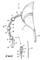
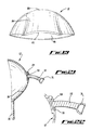
- Fig. 1 is a diagrammatic, partially disassembled, side view of a deflector arrangement according to the present invention;
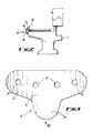
- Fig. 2 is a diagrammatic illustration of the arrangement of Fig. 1 in use on a toilet;
- Fig. 3 is a view in the direction of arrow III in Fig. 1;
- Fig. 4 is a view of one side of a first part of the arrangement of Fig. 1;
- Fig. 5 is a view of the other side of the part of Fig. 4;
- Fig. 6 is an end view of the part of Fig. 4;
- Fig. 7 is a view from above, in the direction of arrow VII of Fig. 4;
- Fig. 8 is a cross-sectional view of a section of a second part of the arrangement of Fig. 1;
- Fig. 9 is a view in the direction IX of Fig. 8;
- Fig. 10 is a view in the direction X of Fig. 8;
- Fig. 11 is a view in the direction XI of Fig. 8;
- Fig. 12 is a side view of a second section of the second part of the arrangement of Fig. 1;
- Fig. 13 is a view in the direction of arrow XIII of Fig. 12;
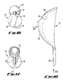
- Fig. 14 is a cross-sectional side view of a third section of a second part of the arrangement of Fig. 1;
- Fig. 15 is a view in the direction of arrow XV of Fig. 14;
- Fig. 16 is a view in the direction of line XVI of Fig. 14;
- Fig. 17 is a view in the direction of XVII of Fig. 14;
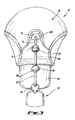
- Fig. 18 is a side view of a deflector of the arrangement of Fig. 1;
- Fig. 19 is a view in the direction XIX of Fig. 18;
- Fig. 20 is a view in the direction of arrow XX of Fig. 18;
- Fig. 21 is a cross-sectional view of the deflector of Fig. 18 with the third section of the second part attached thereto for use for use; and
- Fig. 22 is an enlarged cross-sectional view of the attachment of the said section and deflector of Fig. 21.
-
- Referring to the drawings there is provided a
deflector arrangement 10 comprising adeflector 12 and means 14 to attach thedeflector 12 to a toilet T and enable thedeflector 12 to be selectively moved to and from an operable position in which thedeflector 12 can deflect urine into the toilet T. - In more detail, the means 14 to attach the deflector comprises a first part 16 (Figs. 4 to 7) in the general form of a
base plate 18. Thebase plate 18 is generally curved to locate around the usual curvature of a toilet T to which thearrangement 10 is to be attached (see Fig. 7). A series ofapertures 20 is provided in thebase plate 18 through which securing means (not shown), such as screws or bolts can be used to securely fix thefirst part 16 to a toilet. Alternatively, the apertures may not be completely formed in the plate, but outlined, for example by way of perforations, to be formed if necessary or desired. - The
face 22 of theplate 18 which in use locates against a toilet T is generally smooth. Theface 24 of theother side 26 of theplate 18 comprises an elongate locatingformation 28 of generally "T" shaped cross-section and which extends in use generally downward. Two generally parallel locatingrecesses 30 are provided to be generally symmetrically disposed in spaced configuration on either side of the locatingformation 28. A further locatingrecess 32 is also formed in thebase plate 18 to extend generally perpendicularly between therecesses 30, and just below in use theformation 28. Alobe 34 extends generally downward from one side of the recess, which lobe 34 may bear trade mark or other matter. - An adhesive pad 36 (Fig. 1) is provided to attach the
first part 16 to a toilet T, as will be described. - The attachment means 14 further comprises a first section in the form of a mounting joint 38 (Figs. 8 to 11).
- The
mounting joint 38 comprises amounting body 40 which defines arecess 42 between afront section 44 and anupstanding wall section 46 comprised of two generallyparallel sections 48 connected at one end thereof by afurther section 50. The configuration of theupstanding wall 46 is such that when themounting joint 38 is located in position on thebase plate 18, as will be described, theparallel wall sections 48 locate in therecesses 30, as will be explained. - Extending from the
section 50 generally centrally between and parallel to thesections 48 is afurther section 52 which defines a generally T-shaped channel 54. Thechannel 54 is operable to slidingly receive the locatingformation 28 in use, as will be explained. - A
joint projection 56 extends generally centrally from between thefront section 44 and thesection 50, at an angle of approximately 45°. The projection comprises a ball orpart ball formation 58 on the free end thereof in which is provided arecess 60 which enables theball section 58 to be compressed to locate in a corresponding socket to form a joint as will be explained. - The attachment means 14 further comprises a
second section 62 as shown in Figs. 12 and 13. Thesecond section 62 comprises asocket formation 64 located on one end of acurved body 66 and a part ball shapedjoint formation 68 on the other end of saidcurved body 66. - The attachment means 14 comprises a
third section 70 as shown in Figs. 14 to 17. Thesection 70 comprises acurved body 72 on one end of which is asocket formation 74 similar to thesocket formation 64 described above. Thesocket formation 74 is operable to receive ball or part ball formations otherwise comprised in the attachment means 14 as will be described. - A locating
plate 76 is located on the other end of thecurved body 72. The locating plate is generally in the form of a disc having two curved cut-outs 78 formed in the edge thereof to be generally opposing. - The deflector 12 (Figs. 18 to 20) comprise an upper,
concave portion 80 and a generallyplanar portion 82 extending from the in-use lower edge thereof. The innerconcave surface 84 of theportion 80 is operable to deflect fluid impinging thereon, as will be explained. Theportion 82 acts to guide fluid running from theconcave surface 84, again as will be described. - On the in-
use front 86 of thedeflector 12 is a sleeve or socket 88 (Fig. 20) in which the locatingplate 76 of a thesection 70 is locatable to attach thedeflector 12 to the attachment means 14. Thesleeve 18 is configured to slidingly receive the locatingplate 76 for a snap-fit location ofsmall lugs 90 in the cut-outs 78. Attachment of thesection 70 to thedeflector 12 is illustrated in Figs 21 to 22. - In use, the
arrangement 10 is mountable to the front of a toilet T and in this embodiment is intended for mounting on a front surface of the bowl of a toilet T as shown in Fig. 2. - It is to be appreciated however that it is within the scope of the present invention for the arrangement to be mountable to a seat of the toilet.
- To mount the
arrangement 10, thebase plate 18 is first secured to the front surface of the bowl of the toilet T, to be generally central such that when thedeflector 12 is in the operative position it is located generally between the legs of a person sitting on the toilet T. It will be appreciated however that thebase plate 18 could be mounted in other positions on the toilet. - To mount the
base plate 18, anadhesive pad 36 is used, and if necessary further retaining means, such as bolts (not shown) can be used to locate through theapertures 20 and corresponding apertures formed in the toilet T. - It has been found useful to assemble the rest of the
arrangement 10 before attachment thereof to thebase plate 18, and to this end, the locatingplate 76 of thethird section 70 is slid into thesleeve 88 on thedeflector 12 to securely locate therein with thelugs 90 located in the cut-outs 78. - A
second section 62 is then attached to thefurther section 70 by locating theball formation 68 into thesocket 74. The resilience of theball formation 68 and also thesocket 74 enables theball formation 68 to be pushed into thesocket 70 effectively to form a snap-fit. Theball formation 68 andsocket 74 thereby form a pivotal ball joint. A furthersecond section 62 is then attached to the other end of thefirst section 62 in similar manner. - The mounting joint 38 is then connected to the
socket 64 of the further section again by way of a snap-fit location of theball formation 58 in thesocket 64. - This part assembly of the arrangement 14 is then mounted on the
base plate 18 by offering the mounting joint 38 up to thebase plate 18, such that the locatingformation 28 is at the entrance to the "T" shapedchannel 54 and theparallel sections 48 of thewall 46 are located at the upper ends of therecesses 30. The mounting joint 38 is then slid down over the locatingformation 28 until the locating formation is located within thechannel 54, whereby thearrangement 10 is securely attached to a toilet T. - The ball and socket joints provided between the respective sections provide for versatile movement of the
deflector 12 on the toilet, enabling thedeflector 12 to be moved to and from the operative position. - In the operative position, a
deflector 12 locates generally between the legs of a person sitting on the toilet T. Ideally theconcave portion 18 is located to generally rest on the front of the toilet or toilet seat with theportion 82 extending downward into the toilet. - If a male user of the toilet when in the seated position accidentally directs urine out of the front of the toilet, this would be deflected back into the toilet by the
deflector 12 with theplanar portion 82 further facilitating redirection of the urine into the toilet, thereby preventing or reducing the spoiling of the area outside the toilet. - When the
arrangement 10 is no longer required for use, thedeflector 12 can be simply and easily moved away from the operative position to a stowage position at the front of the toilet. - Various modifications may be made without departing from the spirit or scope of the present invention. For example, the
arrangement 10 may be attached to a toilet using any suitable means, and may be reversibly or irreversibly attached. Any number of pivotal joints may be provided in the arrangement. The arrangement may be integrally formed within a toilet, and particularly in a toilet seat, such as a raised toilet seat. - Whilst endeavouring in the foregoing specification to draw attention to those features of the invention believed to be of particular importance it should be understood that the Applicant claims protection in respect of any patentable feature or combination of features hereinbefore referred to and/or shown in the drawings whether or not particular emphasis has been placed thereon.
Claims (20)
- A deflector arrangement characterised in that the arrangement comprises a deflector and means to attach the deflector to a toilet and enable the deflector to be selectively moved to and from an operable position in which the deflector can deflect urine into the toilet.
- A deflector arrangement according to claim 1, characterised in that the means enables the deflector to be moved between said operable position and one or more further position(s) in which the deflector presents no or substantially no obstacle to a user of the toilet, particularly when the user is getting on and off the toilet.
- A deflector arrangement according to any preceding claim, characterised in that the deflector is located generally at the front of the toilet when in the operable position.
- A deflector arrangement according to claim 3, characterised in that the deflector is located generally centrally whereby to locate between the legs of a person sitting on the toilet.
- A deflector arrangement according to any preceding claim, characterised in that the deflector is located generally beneath the seating area of a toilet.
- A deflector arrangement according to any of claims 2 to 5, characterised in that the deflector is on the outside of the toilet when in the said further position(s).
- A deflector arrangement according to any preceding claim, characterised in that the deflector comprises a concave surface which when in the operable position generally faces a person sitting on the toilet, whereby to direct urine impinging thereon into the toilet.
- A deflector arrangement according to claim 7, characterised in that the deflector extends, in part, into the toilet whereby to facilitate direction of urine therein.
- A deflector arrangement according to any preceding claim, characterised in that the said means comprises a first part attachable to a toilet and a second part operable to enable movement of the deflector on the first part.
- A deflector arrangement according to claim 9, characterised in that the movement is pivotal.
- A deflector arrangement according to claim 9 or claim 10, characterised in that the second part is articulated.
- A deflector arrangement according to claim 11, characterised in that the second part comprises a series of pivotal joints along a length connecting the first part to the deflector.
- A deflector arrangement according to claim 12, characterised in that some or all of the joints are in the form of ball and socket joints or similar to provide multi-axial pivotal movement.
- A deflector arrangement according to any of claims 9 to 13, characterised in that the first part is removably attachable to a toilet.
- A deflector arrangement according to any of claims 9 to 14, characterised in that the first part is attached to adhesive and/or fixings such as threaded fixings.
- A deflector arrangement according to any of claims 9 to 13 and/or claim 15, characterised in that the first part is substantially permanently attached to the toilet.
- A deflector arrangement according to any of claims 9 to 16, characterised in that the arrangement is attachable to the main body or bowl of the toilet.
- A deflector arrangement according to any of claims 9 to 16, characterised in that the arrangement is attachable to a seat member of a toilet.
- A toilet seat characterised in that the seat comprises a deflector arrangement as described in any of the preceding claims.
- A toilet characterised in that the toilet comprises a deflector arrangement as described in any of the preceding claims.
Applications Claiming Priority (2)
| Application Number | Priority Date | Filing Date | Title |
|---|---|---|---|
| GB0114467A GB2376477A (en) | 2001-06-14 | 2001-06-14 | Urine deflector assembly |
| GB0114467 | 2001-06-14 |
Publications (2)
| Publication Number | Publication Date |
|---|---|
| EP1266601A2 true EP1266601A2 (en) | 2002-12-18 |
| EP1266601A3 EP1266601A3 (en) | 2003-12-03 |
Family
ID=9916548
Family Applications (1)
| Application Number | Title | Priority Date | Filing Date |
|---|---|---|---|
| EP02254119A Withdrawn EP1266601A3 (en) | 2001-06-14 | 2002-06-13 | Deflector arrangements |
Country Status (3)
| Country | Link |
|---|---|
| US (1) | US6708350B2 (en) |
| EP (1) | EP1266601A3 (en) |
| GB (1) | GB2376477A (en) |
Cited By (1)
| Publication number | Priority date | Publication date | Assignee | Title |
|---|---|---|---|---|
| US8598409B2 (en) | 2001-02-20 | 2013-12-03 | Intrexon Corporation | Non-human organism comprising a gene expression modulation system encoding a chimeric retinoid X receptor |
Families Citing this family (9)
| Publication number | Priority date | Publication date | Assignee | Title |
|---|---|---|---|---|
| US7007313B1 (en) * | 2004-09-16 | 2006-03-07 | Phillip Johnson | Toilet protector |
| US20060260031A1 (en) * | 2005-05-20 | 2006-11-23 | Conrad Joseph M Iii | Potty training device |
| US8266731B2 (en) * | 2006-03-06 | 2012-09-18 | Takara Belmont Corporation | Toilet seat with urine deflector |
| US20100263115A1 (en) * | 2009-04-21 | 2010-10-21 | Paul Thom | Urine splash guards and splash guard assembly for toilets |
| US20140020165A1 (en) | 2012-07-20 | 2014-01-23 | For Kids By Parents, Inc. | Potty training device |
| US10292548B2 (en) | 2014-05-15 | 2019-05-21 | Sweet Home Ventures | Removable urine deflecting toilet seat attachment |
| WO2018039528A1 (en) * | 2016-08-25 | 2018-03-01 | For Kids By Parents, Inc. | Potty training device |
| US10779694B1 (en) * | 2018-02-27 | 2020-09-22 | Hussain Walker | Toilet trainer |
| US20190365164A1 (en) * | 2018-06-04 | 2019-12-05 | George Alex | Novel urine deflector |
Citations (4)
| Publication number | Priority date | Publication date | Assignee | Title |
|---|---|---|---|---|
| US1857328A (en) * | 1931-01-17 | 1932-05-10 | Piper Frederick | Toilet bowl |
| US2133416A (en) * | 1938-02-21 | 1938-10-18 | George B Bentz | Foldable closet seat deflector |
| US2686320A (en) * | 1948-10-13 | 1954-08-17 | Feldstein Michael | Deflector for infants' toilet seats |
| US3371356A (en) * | 1965-05-24 | 1968-03-05 | Loma Ind Inc | Child's toilet seat assembly |
Family Cites Families (14)
| Publication number | Priority date | Publication date | Assignee | Title |
|---|---|---|---|---|
| US1251877A (en) * | 1915-10-04 | 1918-01-01 | Nellie M Erickson | Bed-pan. |
| US2035567A (en) * | 1935-12-16 | 1936-03-31 | Piper Frederick | Improved closet apron |
| US2141341A (en) * | 1937-08-26 | 1938-12-27 | George B Bentz | Shield for toilet bowl seats |
| US2393050A (en) * | 1942-06-22 | 1946-01-15 | E W Mclellan Co | Device for circular sewing |
| US2545598A (en) * | 1946-10-18 | 1951-03-20 | Taylor Phillips Inc | Folding toilet seat |
| US2703407A (en) * | 1954-03-31 | 1955-03-08 | Rolph E Henoch | Boy's toilet trainer |
| US2850744A (en) * | 1955-06-08 | 1958-09-09 | Jiffy Products | Baby trainer |
| US3614790A (en) * | 1969-05-28 | 1971-10-26 | Max L Billingsly | Anti-noise apparatus for a commode bowl |
| US4716602A (en) * | 1985-09-20 | 1988-01-05 | Todd Brickhouse | Urination deflector |
| US5465431A (en) * | 1994-09-01 | 1995-11-14 | Wertz; Carl F. | Boy's urinal trainer for a toilet |
| US5625905A (en) * | 1995-08-28 | 1997-05-06 | Woods; Michael C. | Urine deflector |
| US5983410A (en) * | 1999-02-04 | 1999-11-16 | Webster; Carla A. | Toilet backsplash and overspray shield |
| US6032302A (en) * | 1999-02-12 | 2000-03-07 | Eckert; Donna M. | Toilet guard system |
| US6408447B1 (en) * | 1999-03-03 | 2002-06-25 | Roderick S. Burbank | Adult urine splash guard |
-
2001
- 2001-06-14 GB GB0114467A patent/GB2376477A/en not_active Withdrawn
-
2002
- 2002-06-12 US US10/171,314 patent/US6708350B2/en not_active Expired - Fee Related
- 2002-06-13 EP EP02254119A patent/EP1266601A3/en not_active Withdrawn
Patent Citations (4)
| Publication number | Priority date | Publication date | Assignee | Title |
|---|---|---|---|---|
| US1857328A (en) * | 1931-01-17 | 1932-05-10 | Piper Frederick | Toilet bowl |
| US2133416A (en) * | 1938-02-21 | 1938-10-18 | George B Bentz | Foldable closet seat deflector |
| US2686320A (en) * | 1948-10-13 | 1954-08-17 | Feldstein Michael | Deflector for infants' toilet seats |
| US3371356A (en) * | 1965-05-24 | 1968-03-05 | Loma Ind Inc | Child's toilet seat assembly |
Cited By (1)
| Publication number | Priority date | Publication date | Assignee | Title |
|---|---|---|---|---|
| US8598409B2 (en) | 2001-02-20 | 2013-12-03 | Intrexon Corporation | Non-human organism comprising a gene expression modulation system encoding a chimeric retinoid X receptor |
Also Published As
| Publication number | Publication date |
|---|---|
| EP1266601A3 (en) | 2003-12-03 |
| GB2376477A (en) | 2002-12-18 |
| US20020194672A1 (en) | 2002-12-26 |
| US6708350B2 (en) | 2004-03-23 |
| GB0114467D0 (en) | 2001-08-08 |
Similar Documents
| Publication | Publication Date | Title |
|---|---|---|
| US6708350B2 (en) | Deflector arrangements | |
| US6055681A (en) | Urinal anti-splash-back apparatus and associated methods | |
| US5848822A (en) | Folding collapsible chair | |
| US5251338A (en) | Toilet height conversion apparatus | |
| US6408447B1 (en) | Adult urine splash guard | |
| US7007313B1 (en) | Toilet protector | |
| US4964179A (en) | Toilet seat for disabled persons | |
| AU2008203055A1 (en) | Toilet Seat Elevator Assembly | |
| US20080016607A1 (en) | Liquid shield for use in connection with a toilet seat | |
| US11193263B1 (en) | Fastener cover for bidet attachment | |
| US6289527B1 (en) | Toilet sanitary device | |
| EP0553184A1 (en) | Bathtub assembly having contoured walls and accessories | |
| DE69706975T2 (en) | DEVICE FOR FASTENING ABOVE A CLOSET BOWL AND CLOSET ARRANGEMENT | |
| USD483978S1 (en) | Portion of a sleep collar | |
| KR200189721Y1 (en) | Upholding body to use the back of chair | |
| US20020002737A1 (en) | Pail/splash guard for commode | |
| US5704075A (en) | Stay-dry toilet seat | |
| KR200425324Y1 (en) | The fold type stool for bathroom | |
| US5860169A (en) | Stay-dry toilet seat with adjustable hinged support pads | |
| KR200178519Y1 (en) | Upholding body to use the back of chair | |
| KR200172221Y1 (en) | Waist-supporting device mounted on a chair | |
| EP1475483B1 (en) | Smell extractor device for toilet bowls | |
| KR200240463Y1 (en) | A toilet bowl support | |
| JP3528528B2 (en) | Chair armrest equipment | |
| EP2057926B1 (en) | Lavatory accessory |
Legal Events
| Date | Code | Title | Description |
|---|---|---|---|
| PUAI | Public reference made under article 153(3) epc to a published international application that has entered the european phase |
Free format text: ORIGINAL CODE: 0009012 |
|
| AK | Designated contracting states |
Kind code of ref document: A2 Designated state(s): AT BE CH CY DE DK ES FI FR GB GR IE IT LI LU MC NL PT SE TR |
|
| AX | Request for extension of the european patent |
Free format text: AL;LT;LV;MK;RO;SI |
|
| PUAL | Search report despatched |
Free format text: ORIGINAL CODE: 0009013 |
|
| AK | Designated contracting states |
Kind code of ref document: A3 Designated state(s): AT BE CH CY DE DK ES FI FR GB GR IE IT LI LU MC NL PT SE TR |
|
| AX | Request for extension of the european patent |
Extension state: AL LT LV MK RO SI |
|
| RIC1 | Information provided on ipc code assigned before grant |
Ipc: 7A 47K 17/00 B Ipc: 7A 47K 13/24 A |
|
| AKX | Designation fees paid | ||
| REG | Reference to a national code |
Ref country code: DE Ref legal event code: 8566 |
|
| STAA | Information on the status of an ep patent application or granted ep patent |
Free format text: STATUS: THE APPLICATION IS DEEMED TO BE WITHDRAWN |
|
| 18D | Application deemed to be withdrawn |
Effective date: 20040604 |