EP1265786B1 - Apparatus and methods for applying flexible straps around bundles of objects - Google Patents
Apparatus and methods for applying flexible straps around bundles of objects Download PDFInfo
- Publication number
- EP1265786B1 EP1265786B1 EP00980795A EP00980795A EP1265786B1 EP 1265786 B1 EP1265786 B1 EP 1265786B1 EP 00980795 A EP00980795 A EP 00980795A EP 00980795 A EP00980795 A EP 00980795A EP 1265786 B1 EP1265786 B1 EP 1265786B1
- Authority
- EP
- European Patent Office
- Prior art keywords
- strap
- cover
- feed
- track
- slotted cover
- Prior art date
- Legal status (The legal status is an assumption and is not a legal conclusion. Google has not performed a legal analysis and makes no representation as to the accuracy of the status listed.)
- Expired - Lifetime
Links
Images









Classifications
-
- B—PERFORMING OPERATIONS; TRANSPORTING
- B65—CONVEYING; PACKING; STORING; HANDLING THIN OR FILAMENTARY MATERIAL
- B65B—MACHINES, APPARATUS OR DEVICES FOR, OR METHODS OF, PACKAGING ARTICLES OR MATERIALS; UNPACKING
- B65B13/00—Bundling articles
-
- B—PERFORMING OPERATIONS; TRANSPORTING
- B65—CONVEYING; PACKING; STORING; HANDLING THIN OR FILAMENTARY MATERIAL
- B65B—MACHINES, APPARATUS OR DEVICES FOR, OR METHODS OF, PACKAGING ARTICLES OR MATERIALS; UNPACKING
- B65B13/00—Bundling articles
- B65B13/18—Details of, or auxiliary devices used in, bundling machines or bundling tools
- B65B13/22—Means for controlling tension of binding means
-
- B—PERFORMING OPERATIONS; TRANSPORTING
- B65—CONVEYING; PACKING; STORING; HANDLING THIN OR FILAMENTARY MATERIAL
- B65B—MACHINES, APPARATUS OR DEVICES FOR, OR METHODS OF, PACKAGING ARTICLES OR MATERIALS; UNPACKING
- B65B13/00—Bundling articles
- B65B13/18—Details of, or auxiliary devices used in, bundling machines or bundling tools
-
- B—PERFORMING OPERATIONS; TRANSPORTING
- B65—CONVEYING; PACKING; STORING; HANDLING THIN OR FILAMENTARY MATERIAL
- B65B—MACHINES, APPARATUS OR DEVICES FOR, OR METHODS OF, PACKAGING ARTICLES OR MATERIALS; UNPACKING
- B65B59/00—Arrangements to enable machines to handle articles of different sizes, to produce packages of different sizes, to vary the contents of packages, to handle different types of packaging material, or to give access for cleaning or maintenance purposes
- B65B59/003—Arrangements to enable adjustments related to the packaging material
-
- B—PERFORMING OPERATIONS; TRANSPORTING
- B65—CONVEYING; PACKING; STORING; HANDLING THIN OR FILAMENTARY MATERIAL
- B65B—MACHINES, APPARATUS OR DEVICES FOR, OR METHODS OF, PACKAGING ARTICLES OR MATERIALS; UNPACKING
- B65B59/00—Arrangements to enable machines to handle articles of different sizes, to produce packages of different sizes, to vary the contents of packages, to handle different types of packaging material, or to give access for cleaning or maintenance purposes
- B65B59/005—Adjustable conveying means
-
- B—PERFORMING OPERATIONS; TRANSPORTING
- B65—CONVEYING; PACKING; STORING; HANDLING THIN OR FILAMENTARY MATERIAL
- B65B—MACHINES, APPARATUS OR DEVICES FOR, OR METHODS OF, PACKAGING ARTICLES OR MATERIALS; UNPACKING
- B65B2210/00—Specific aspects of the packaging machine
- B65B2210/12—Means for automatically detecting and removing jammed straps in strapping machines, e.g. jam clearing devices
Definitions
- This invention relates to apparatus and methods for applying flexible straps around bundles of objects.
- Typical strapping machines employ an initial or primary tensioning apparatus that provides an initial tensioning of the strap about the bundle.
- a secondary tensioning apparatus thereafter provides increased or enhanced tension of the strap.
- a sealing head then seals the strap, typically through the use of a heated knife mechanism, to complete the bundling operation.
- the arch type band guide includes corner elements and straight elements, each having the same shape and the same size, wherein the elements are connected in a manner capable of swinging in an arch unit, whereby various sizes of band guide can be easily fabricated depending on the size of articles to be packed.
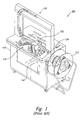
- FIG. 1 is a strapping machine 100 in accordance with the prior art, as shown and described in U.S. Patent No. 5,414,980, issued to Shibazaki et al.
- the strapping machine 100 includes the following major components, all mounted to a housing or frame 110: a strap dispenser 112, an accumulator 114, a feed and tension unit 116, a track 118, a sealing head 122, and a control system 124.
- some devices also have a secondary tension unit 120 (not shown), such as the type disclosed in U.S. Patent No. 3,552,305 issued to Domey et al.
- the basic operation of the machine involves a feeding cycle and a strapping cycle.
- strap is pulled from a strap coil mounted on the dispenser 112 by a feed and tension motor and is fed through the accumulator 114, the feed and tension unit 116. the sealing head 122. and the track 118. After the strap has been fed around the track 118 and back into the sealing head 122, the strapping cycle begins.
- the strapping machine performs several functions. First, the sealing head 122 of the strapping machine grips the free end of the strap, holding it securely. Next, in a primary tensioning sequence, a track guide mechanically opens and the strap is pulled from the track 118 as the strap is drawn around the bundle by a feed and tension motor.
- additional strap tension may be applied by the secondary tension unit 120.
- the sealing head 122 grips the supply side of the strap.
- the overlapping strap sections are then heated by a heater blade, pressed together by a press platen, and severed from the supply by a strap cutter 140.
- the strap path through the sealing head 122 is once again aligned and the feeding sequence can begin.
- the sealing head 122 continues to rotate allowing the seal to cool while the feeding sequence continues.
- the sealed strap is released and the strapping machine 100 is ready to repeat the feeding cycle.
- the prior art feed and tension unit 116 typically includes a complicated series of strap guides.
- the strap must be fed through the strap guides, undergoing several bends and turns between the dispenser 112 and the sealing head 122.
- Existing strapping machines typically turn the strap through a total of 360 degrees or more before reaching the track.
- the bends and turns in the strap path may induce kinks in the strap that may subsequently lead to feeding difficulties. If the strap becomes jammed in the feed and tension unit 116, the process of clearing the strap path from the complicated series of strap guides may be time-consuming and may require machine downtime.
- the present invention improves upon prior strapping devices, and provides additional benefits, such as by providing variability in the apparatus that can be easily altered to fit various production and package requirements and by employing a control system that monitors operating signals and transmits control signals accordingly.
- a feed and tension unit under one aspect of the invention includes three sets of wheels: (1) a feeding set including a feed drive roller and a feed pinch roller, (2) a primary tensioning set including a primary tension drive roller and a primary tension pinch roller, and (3) a secondary tensioning set including a secondary tension drive roller and a secondary tension pinch roller, and wherein at least one of the feed pinch roller, the primary tension pinch roller, or the secondary tension pinch roller is coupled to a solenoid that controllably biases the pinch roller against the respective drive roller based on a pinch signal supplied to the solenoid, the pinch signal having a first pulse width modulated stage that provides a full pinch force and a second pulse width modulated stage that provides a reduced pinch force.
- a control system monitors position signals from a feed pinch roller position sensor and terminates primary tensioning when a slippage condition is determined. The control system then initiates a secondary tensioning operation. The secondary tensioning operation lasts for a predetermined amount of time, then the control system initiates a joining operation that secures the strap around the bundle.
- the three sets of wheels or rollers of the feed and tension unit are configured to provide a simplified strap path that reduces bending of the strap, thereby reducing friction and consequent feeding difficulties.
- the drive wheels of the feed and tension unit may be positioned on the side of the strap opposite from the bundle to reduce adverse effects of debris from the bundle.
- the feed and tension unit includes inner and outer guides that form a strap channel through the feed and tension unit. The inner and outer guides are configured to provide easy access to the strap path for clearing the strap path in the event of a jam.
- a strap material accumulating compartment includes a first sidewall having a plurality of mounting posts projecting therefrom, each mounting post having a plurality of mounting holes disposed therethrough, a second sidewall having a plurality of mounting apertures alignable with and slideably engageable with the mounting posts, and a plurality of pin holders positioned proximate the mounting apertures, and a plurality of mounting pins removably and adjustably engageable with the mounting holes and the pin holders.
- the first and second sidewalls approximately form a chamber therebetween wherein the strap may accumulate. The width of the chamber may be adjusted easily and quickly to accommodate varying widths of strap by removal of the retaining pins, repositioning the second sidewall at the desired location, and replacement of the retaining pins within the desired holes.
- the track assembly includes a plurality of sections providing modularity of construction.
- Each section includes a backplate attached to at least one support member, and a slotted cover pivotably attached to the at least one support member proximate the backplate and moveable between an open position spaced apart from the backplate and a closed position proximate the backplate, and a biasing member engaged with the slotted cover that exerts a biasing force on the slotted cover to urge the slotted cover toward the closed position.
- the biasing force is small enough that a tensioning force in the strap material may overcome the biasing force and thereby actuate the slotted cover toward the open position to allow the strap material to escape from the guide passage during a tension cycle.
- the strap material exerts a closing force on an outer surface of the slotted cover, urging the slotted cover into the closed position.
- the slotted covers are pivotably mounted on guide pins that are approximately parallel to the path of the strap material within the guide passage.
- a cutting assembly for severing strap material includes a press platen and a cutter having a first cutting blade along a first edge thereof and a second cutting blade along a second edge thereof, the cutter being removably and variably engaged to the press platen such that at least one of the first or second cutting blades is engageable with the strap material.
- at least one of the first and second edges is slanted at a slant angle with respect to an adjacent edge of the cutter.
- the present disclosure is directed toward apparatus and methods for strapping bundles of objects.
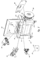
- FIG. 2 is an isometric view of a strapping machine 200 in accordance with an embodiment of the invention.
- the strapping machine 200 includes seven major subassemblies: a frame 210, a control system 220, a dispenser 250, an accumulator 300, a feed and tension unit 350, a sealing head 400, a drive assembly 500, and a track 450.
- the subassemblies are of modular construction, which allows them to be used in multiple frame configurations.
- the strap material is shown and referred to as a particular type of material, namely, a flat, two-sided, tape-shaped strip of material. This practice is adopted herein solely for the purpose of simplifying the description of the inventive methods and apparatus. It should be understood, however, that several of the methods and apparatus disclosed herein may be equally applicable to various types of strap material, and not just to the flat. two-sided, tape-shaped material shown in the figures. Thus, as used herein, the terms "strap” and “strap material” should be understood to include all types of materials used to bundle objects.
- the operation of the strapping machine 200 involves paying off strap 202 from a strap coil 204 located on the dispenser 250 ( Figures 17-18), and feeding a free end 206 of the strap 202 through the accumulator 300 ( Figures 14-16), the feed and tension unit 350 (Figures 10-13), the sealing head 400 ( Figures 3-5), and around the track 450 ( Figures 19-20). After the strap 202 is fed around the track 450, the free end 206 is fed back into the sealing head 400. At this point the strap 202 is in position to start a strapping cycle.
- the cams 402 operate as cycloidal cams allowing the sealing head 400 to operate smoothly at increased speeds and the cam follower pressure angles are minimized to extend cam life.
- cycloidal cam means a cam with cycloidal displacement generated by taking a sinusoidal acceleration function that has a magnitude of zero at its beginning and end, and integrating the function to obtain the velocity and displacement of the follower.
- the press platen 412 presses both ends against the anvil 406 ( Figure 3) for bonding and cooling.
- the sealing head cams 402 continue to rotate, the press platen 412 lowers slightly allowing the anvil 406 to open and release the sealed strap.
- the anvil 406 is closed and the strapping cycle is completed by feeding strap 202 through the sealing head 400, around the track 450, back into the sealing head 400 and finally actuating a feed stop switch 416 ( Figure 3).
- the manual mode applies single or multiple straps while an operator actuates a switch.
- the automatic mode applies a single strap or multiple straps when a switch is actuated by a moving bundle.
- the automatic mode is used in conveyor lines and in conjunction with other automated machinery.
- the frame 210 consists of a main support 212, adjustable legs 214, and cover plates 216.
- the frame 210 provides structural support for all of the other sub-assemblies of the strapping machine 200.
- the strap 202 is fed about the track 450 in a strap-feed direction 209 that is generally counterclockwise.
- the strapping machine 200 is controlled by a control system 220 that may include a programmable logic controller 222 ( Figure 3) that operates in conjunction with various input and output devices and controls the major subassemblies of the strapping machine 200.
- Input devices may include, for example, momentary and maintained push buttons, selector switches, toggle switches, limit switches and inductive proximity sensors.
- Output devices may include, for example, solid state and general purpose relays, solenoids, and indicator lights. Input devices are scanned by the controller 222, and their on/off states are updated in a controller program 224.
- the controller 222 executes the controller program 224 and updates the status of the output devices accordingly. Other control functions of the controller 222 are described below in further detail.
- the programmable controller 222 and its associated input and output devices may be powered using a 24 VDC power supply.
- the controller 222, power supply, relays, and fuses may be contained within a control panel (not shown).
- the momentary and maintained push buttons, selector switches, and toggle switches may be located on a control pendant or a control panel cover.
- the limit switches, inductive proximity sensors, and solenoids are typically located within the strapping machine 200 at their point of use.
- At least one indicator light may be mounted on the top of the track 450 and may light steadily to indicate an out-of-strap condition, and may flash to indicate a strap misfeed condition.
- One commercially-available programmable controller 222 suitable for use with the strapping machine 200 is the T100MD1616+ PLC manufactured by Triangle Research International Pte Ltd in Singapore.
- This device includes sixteen NPN-type digital outputs, four of which are NPN Darlington Power Transistor types and twelve of which are N-channel power MOSFET types. Two of the outputs are capable of generating a Pulse Width Modulated (PWM) signal with a frequency and duty cycle determined in the programming software.
- PWM Pulse Width Modulated
- Also included are four input channels of 10-bit analog-to-digital converters. Two of the input channels are buffered by operational amplifiers with a x5 gain accepting analog signals of 0-1V full scale. The remaining two channels are unbuffered and accept 0-5V full scale analog signals.
- the unit includes a stable 5V (+/- 1% accuracy) regulated DC power supply to be used as a voltage reference for the analog inputs.
- the T100MD1616+ PLC has communication ports, including an RS232C port for program uploads, downloads and monitoring, a two-wire RS485 network port, a 14-pin LCD display port for possible future use as a diagnostic display driver, and a port for expansion.
- the PLC itself is controlled by a custom CPU that has both EEPROM and RAM memory backup.
- the controller program 224 used to program the controller 222 may, for example, include Trilogi programming software available from Triangle Research International Pte Ltd, and may include both ladder logic and Tbasic type code (described more fully at www.tri.com.sg/index.htm).
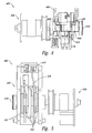
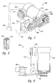
- FIG 3 is an isometric view of the sealing head 400 of the strapping machine 200 of Figure 2.
- Figures 4 and 5 are top elevational and back elevational views, respectively, of the sealing head 400 of Figure 3.
- Figure 6 is an isometric view of the press platen 412 and the cutter 414 of the sealing head 400 of Figure 3.
- the sealing head 400 comprises a motor-driven main shaft 418 and a series of cams 402 which perform gripping, sealing and cutting functions. These cams 402 drive three sliding members 422 and three rotating arms 424 ( Figure 5).
- One slide member 422 is coupled to the right-hand gripper 408, another slide member 422 is coupled to the left-hand gripper 404, and the third slide member 422 is coupled to the press platen 412.
- the sliding members 422 perform the gripping, sealing and cutting functions, while the pivoting arms 424 move an inner slide 420, the anvil 406, and the heater blade 410 into and out of a strap path as required during a strapping cycle.
- FIG 22 is an exploded isometric view of the press platen 412 and cutter 414 of Figure 6.
- the press platen 412 includes a pair of mounting nubs 411
- the cutter 414 includes mounting recesses 413.
- a spring 415 is disposed between the cutter 414 and the press platen 412, one end of the spring 415 being partially disposed within a seating hole 417 disposed in the press platen 412.
- the cutter 414 has cutting edges 419 at both ends, allowing the cutter 414 to be reversibly positioned on the press platen 412 for added operational life.
- the cutting edges 419 are slanted at an angle ⁇ . Although a wide variety of cutting edge angles ⁇ may be used, a cutting edge angle in the range of approximately 9 degrees or less is preferred.
- the spring 415 is compressed between the cutter 414 and the press platen 412 until the two mounting recesses 413 slideably engage two of the mounting nubs 411.
- the cutter 414 has a pair of mounting recesses 413 situated near each end of the cutter 414 which allows the cutter 414 to be reversibly mounted onto the press platen 412.
- the cutter 414 and the press platen 412 are then positioned securely between the left and right-hand grippers 404, 408 with the pressure from these parts maintaining the compression of the spring 415.
- the cutter 414 and press platen 412 are then engaged with the third slide member 422. This arrangement provides the necessary scissors action to sever the strap 202.
- An advantage of the cutter 414 and press platen 412 assembly shown in Figures 6 and 22 is that the cutter 414 is removably and replaceably mounted to the press platen 412 by slideably engaging onto the press platen 412. This allows the cutter 414 to be more easily removed for replacement or maintenance than in the prior art devices. The reversibility of the cutter 414 also essentially doubles the useful life of the component.
- FIG 7 is an isometric view of a main drive assembly 500.
- Figures 8 and 9 are top and side elevational views, respectively, of the main drive assembly 500 of Figure 7.
- the main drive assembly 500 includes a main drive motor 502 that drives a sealing head drive belt, 508 and a drive wheel belt 510.
- the sealing head drive belt 508 and the drive wheel belt 510 are preferably "toothed" belts.
- the sealing head drive belt 508 is directly coupled to a spring clutch 504.
- the drive wheel belt 510 is turned approximately 90 degrees on a pair of drive pulleys 512 and is coupled to the drive wheel clutch 356.
- the main drive motor 502, the spring clutch 504, and the drive wheel clutch 356 are operatively coupled to the controller 222, such as, for example, by electrically conductive leads 223.
- main drive assembly 500 One advantage of the main drive assembly 500 is that the drive wheel clutch 356 is driven by the drive wheel belt 510, which is turned at an approximately 90 degree angle on the drive pulleys 512. This arrangement. commonly referred to as a "mule drive,” eliminates a 90-degree gearbox commonly found in drive systems of prior art strapping machines. Thus, the complexity and costs of fabrication of the main drive assembly 500 are reduced, and reliability and maintainability is improved.
- the spring clutch 504 is a wrap spring clutch and the drive wheel clutch 356 is an electromagnetic clutch. Alternately, other spring clutch 504 and drive wheel clutch 356 embodiments may be used.
- the spring clutch 504 stops the sealing head cams 402 at the proper degree of rotation during each stage of the cycle and stops the cams 402 in their home position at the end of each cycle.
- the drive wheel clutch 356 slips at a torque that is determined by the voltage supplied to a coil located within the electromagnetic drive wheel clutch 356. The slip in the drive wheel clutch 356 determines the amount of secondary tension that is applied to the strap 202.
- the main drive motor 502 drives the sealing head 400 by means of the sealing head drive belt 508 and the spring clutch 504 ( Figures 7 and 8) which is mounted over an end of the sealing head main shaft 418 ( Figure 3). Rotation of the main shaft 418 causes the keyed cams 402 ( Figures 3 and 5) to rotate and perform the necessary gripping, sealing and cutting functions. During a first period of rotation, the main shaft 418 rotates to the first of three stops on the spring clutch 504, causing a cutter-gripper assembly 426 to grip the strap 202 and the inner slide 420 to move out of the strap path. The main drive motor 502 then tensions the strap about the bundle, as will be described more fully below. When the strap tensioning is complete, the controller 222 pulses the spring clutch 504 allowing the cams 402 to rotate in a second period of rotation.
- the right-hand gripper 404 grips the tensioned strap just ahead of the feed stop switch 416 and the tension in the strap is then released.
- the platen 412 and the cutter 414 ( Figures 6 and 22) rise to cut the strap 202 and press the strap against the heater blade 410.
- the cams 402 continue to rotate through a dwell section as the strap 202 melts on the heater blade 410.
- the press platen 412 and the cutter 414 retract slightly allowing the heater blade 410 to retract.
- the press platen 412 rises again to press the two melted ends of the strap 202 together for cooling and sealing.
- the sealing head main shaft 418 continues to rotate during a third period of rotation until a clutch trigger 428 disengages the spring clutch 504.
- the sealing head 400 maintains this position for a predetermined time until the controller 222 again energizes a spring clutch solenoid 506 (not shown) located within the spring clutch 504.
- the continued rotation of the cams 402 releases the press platen 412 and drops the left and right-hand grippers 404, 408 to their home positions.
- One of the cams 402 then pivots the anvil 406 out of the strap line past a pair of strippers 430.
- the strippers 430 push the strap off of the anvil 406.
- the anvil 406 closes, and the cams 402 reach their home positions.
- the spring clutch 504 reaches the third and final stop as the feed stop switch 416 ( Figure 3) signals the controller 222 to begin another feed sequence.
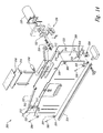
- Figure 10 is a first isometric view of the feed and tension unit 350.
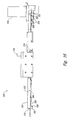
- Figures 11 and 12 are a second isometric view and a partial front elevational view, respectively, of the feed and tension unit 350 of Figure 10.
- the feed and tension unit 350 pinches the strap 202 between each of the three sets of drive wheels and pinch wheels.
- the feed, primary tension, and secondary tension pinch wheels 366, 360, 362 are engaged against the strap 202 by a feed pinch solenoid 370a, a primary tension pinch solenoid 370b, and a secondary tension pinch solenoid 370c, respectively.
- the drive wheel clutch 356 is powered by a drive wheel belt 510 from the main drive motor 502.
- the primary tension and feed drive wheels 360, 366 are powered by a secondary drive belt 372 mounted on a feed and tension motor 361.
- the secondary tension drive wheel 362 is powered by the drive wheel clutch 356 that is driven by the drive wheel belt 510 from the main drive motor 502.
- the feed and tension motor 361, and the solenoids 370a, 370b, 370c are operatively coupled to the controller 222 by conductive leads 223.
- the strapping machine 200 features a simplified strap path (Figure 12) allowing the strap to be red in a straighter path than previously achievable.
- the path begins at the supply dispenser 250 that is located on the opposite side of the strapping machine from the feed and tension unit. This position further enables the strap to travel in a less tortuous path.
- the drive wheels 360, 366, and 362 are positioned in an approximately triangular orientation, with the strap 202 traversing an approximately "V-shaped" strap path having an included angle of in the range of approximately 20 degrees to approximately 40 degrees. Less bending of the strap reduces friction throughout the system, increasing the reliability of strap feeding.
- the feed and tension unit 350 of the present invention advantageously reduces or eliminates kinks in the strap which lead to feeding difficulties. While the strapping machines of the prior art typically turned the strap through a total of 360 degrees or more prior to reaching the track, the feed and tension unit 350 greatly reduces the amount of turning of the strap. For example, in the embodiment shown in the accompanying figures, the strap is turned through between approximately 180 and approximately 220 degrees as the strap is initially fed from the dispenser 250 across the strapping machine to the sealing head 400.
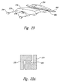
- FIG 23 is an enlarged partially-exploded isometric view of a pair of inner and outer strap guides 374, 376 of the feed and tension unit 350 of Figure 10.
- each "L-shaped" inner guide 374 has a roughly L-shaped cross-section and is coupled to a matching "L-shaped" outer guide 376 to form a strap channel 380 through which the strap 202 passes.
- Figure 23A is a cross-sectional view of the inner guide 374 and outer guide 376 and illustrates the guide chamber formed by the inner and outer guides to guide the strap material 202.
- the inner and outer guides 374, 376 are secured in position on a plurality of guide pins 378 which project from a back plate 382 ( Figure 10) of the feed and tension unit 350 by a plurality of retaining knobs 379, although a variety of other securing devices may be used.
- one of the outer guides 376 is removed from the strap path adjacent to the primary tension pinch and drive wheels 352, 360 to provide a view of one of the "L-shaped" inner guides 374.
- a feed force applied by the feed drive and pinch wheels 366, 368 is regulated by a pulse width modulated solenoid 370a in two stages: a first stage that provides a full feed force and a second stage that provides a reduced feed force by altering the pulse width modulation of the feed pinch solenoid 370a. Because the pinch force exerted by a solenoid 370a on the strap 202 varies with supplied voltage, supplying a pulse width modulated voltage signal to the solenoid 370a provides the ability to vary the force exerted by the solenoid 370a.
- solenoids suitable for this purpose include those solenoids available from Ledex® Actuation Products of Vandalia, Ohio.
- the frequency of the pulses which are fed to the solenoid affects the operation and performance of the solenoid. Generally, as the frequency of the pulses is increased, the adjustability of the pinch force exerted by the solenoid is improved. For example, using the above-referenced solenoids available from Ledex® Actuation Products, a pulse frequency of 8000 Hz has been successfully used.
- the feed drive and pinch wheels 366, 368 feed the strap through the sealing head 400, around the track 450, and back into the sealing head 400.
- the arrival of the free end 206 is detected by feed stop switch 416, which transmits a feed stop signal to the controller 222.
- the controller 222 then sends a feed pinch signal to the feed pinch wheel 368 to disengage the feed pinch wheel 368 from the strap 202, and the feeding sequence is complete.
- the strap 202 is pinched between the primary tension drive wheel 360 and the primary tension pinch wheel 352.
- the primary tension solenoid 370b engages the primary tension pinch wheel 352 against the primary tension drive wheel 360 with full pinch force to ensure that the primary tensioning solenoid engages and the strap 202 is pulled free of the track 450.
- the pinch force is then reduced during a second primary tension stage by altering the pulse width modulation of the primary tension solenoid 370b.
- the primary tension pinch wheel 352 stops rotating due to the slippage of the strap on the primary tensioning drive wheel 360.
- Using pulse width modulation to control the pinch forces exerted by the solenoids 370a, 370b during feeding and primary tensioning of the strap advantageously allows the operator a larger range of adjustment than is possible with a mechanical, single force adjustment system of the prior art.
- the two-stage force operation provides improved controllability of the strap 202 movement, including allowing the strap 202 to be quickly accelerated and to be easily stopped as required by the operator.
- Figure 13 is an isometric view of the primary tension pinch wheel 352 and the proximity sensor 354 of the feed and tension unit 350 of Figure 10.
- the proximity sensor 354 is operatively coupled to the controller 222.
- the proximity sensor 354 monitors the primary tension pinch wheel 352 during primary tensioning, such as by monitoring the passing of notches in the wheel 352, to detect the stall of the primary tension pinch wheel 352.
- the proximity sensor 354 transmits signals to the controller 222. As the signals from the proximity sensor 354 indicate that the primary tension pinch wheel 352 is not turning due to the slippage of the strap 202 on the primary tension drive wheel 360, the controller 222 starts a secondary tensioning sequence.
- the secondary tensioning sequence begins by pinching the strap between the secondary tension pinch wheel 364 and the secondary tension drive wheel 362. Then, the secondary tension drive wheel 362 is driven by the drive wheel clutch 356 until the drive wheel clutch 356 starts to slip. After the strap 202 is tensioned to the point that the drive wheel clutch 356 slips, the controller 222 permits a predetermined amount of time to pass to allow the strap to be cut and sealed as described above. The feeding sequence may then be repeated.
- An advantage of the strapping machine 200 is that the pinch wheels 352, 364, 368 are actuated by the solenoids 370a, 370b, 370c.
- PWM pulse width modulated
- the solenoids are adjustably controllable by the user during strapping machine 200 operation.
- the solenoid is given a PWM signal at a constant duty cycle.
- the solenoid is controlled using a PWM signal with a duty cycle that is user-adjustable via, for example, a potentiometer. Since the average voltage seen by the solenoid is determined by the duty cycle, varying the duty cycle will vary the amount of force the solenoid pulls.
- the pinch wheels 352, 364, 368 may be adjustably controlled during operation of the strapping machine 200, eliminating the labor-intensive process of mechanical re-adjustment of the pinch wheels 352, 364, 368 and the associated downtime of the strapping machine.
- Figure 14 is an exploded isometric view of an accumulator 300.
- Figures 15 and 16 are front and top elevational views, respectively, of the accumulator 300 of Figure 15 taken along line 24-24.
- the accumulator 300 includes first and second sidewalls 302, 304 that substantially enclose a chamber 306 that stores strap for rapid feeding, as well as for temporarily storing of the strap 202 that is drawn back in the tensioning process.
- the second sidewall 304 is incrementally adjustable by placing retaining pins 308 in a series of holes 310 located in shafts 312 that protrude from the first sidewall 302 to accommodate different sizes of strap 202.
- Pin holders 309 are attached to the second sidewall 304 which engage the retaining pins 308 and fix the position of the second sidewall 304 on the shafts 312.
- the chamber 306 is substantially enclosed by the first sidewall 302 and the adjustable second sidewall 304.
- a pair of endwalls 320 extend vertically between the first and second sidewalls 302,304.
- a top wall 322 extends horizontally along between the first and second sidewalls 302,304, the top wall 322 having the top entrance 316 where strap 202 is fed into and pulled out of the accumulator unit 300.
- An "L" shaped wand 324 extends between the first and second sidewalls 302,304 along the bottom of the chamber 306. The wand 324 is pivotally attached to the first sidewall 302.
- an accumulator motor 330 ( Figure 14) drives an accumulator drive wheel 332 to feed the strap 202 between the accumulator drive wheel 332 and an accumulator pinch wheel 334.
- An accumulator feed switch 336 ( Figure 14) is positioned proximate the accumulator drive and pinch wheels 332,334 to detect the presence of the strap 202 and to transmit a control signal to the accumulator motor 330.
- the wand 324 is pushed downwardly by the weight of the strap 202, pivoting the wand 324 into contact with an indicator switch 326 ( Figure 15).
- the indicator switch 326 then transmits a signal to the controller 222 to shut off the accumulator motor 330, as described more fully below.
- a strap diverter 314 covers a top entrance 316 of the chamber 306.
- a diverter solenoid 318 ( Figure 14) pulls the strap diverter 314 over the top entrance 316 of the chamber 306, diverting the strap 202 directly into the feed and tension unit 350 and around the track 450.
- the accumulator 300 advantageously allows the width w of the chamber 306 and the top entrance 316 to be adjusted easily and quickly to accommodate varying widths of strap 202.
- the accumulator 300 of the present invention includes shafts 312 having a plurality of holes 310 placed at increments to match various commonly used strap sizes.
- the position of the second sidewall 304 with respect to the first sidewall 302 may be quickly and easily varied by removal of the retaining pins 308, repositioning the second sidewall 304 at the desired location, and replacement of the retaining pins 308 within the desired holes 310.
- the pin holders 309 then engage against the retaining pins 308 and fix the position of the second sidewall 304 on the shafts 312.
- This mounting configuration allows the adjustment of the accumulator without having any additional parts, such as spacers between the first and second sidewalls 302, 304.
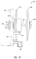
- FIG 17 is an isometric view of a dispenser 250.
- Figure 18 is a top elevational view of the dispenser 250 of Figure 17.
- the dispenser 250 includes a mounting shaft 252 extending outwardly from the frame 210 between an inner hub 254 and an outer hub 256.
- a spring brake 258 is operatively coupled to the mounting shaft 252 and to the frame 210. When actuated, the brake 258 allows the rotation of the mounting shaft 252.
- a mandrel 260 is rotatably mounted on the mounting shaft 252 and supports the inner hub 254 and the outer hub 256.
- Strap 202 is routed from the strap coil 204 around a first pulley 262 and a second pulley 264 and over a strap exhaust switch 266.
- the accumulator motor 330 is energized and the dispenser brake 258 released, allowing the strap coil 204 to spin freely and strap 202 to feed into the chamber 306.
- the brake 258 releases the strap coil 204 to spin only when power is supplied to the brake 258.
- the strap exhaust switch 266 is no longer actuated which stops the strapping machine 200 until the strap coil 204 is replenished.
- a braking circuit is used to prevent the accumulator motor 330 from drawing the free end 206 of the strap into the accumulator 300. The remaining loose tail of strap can then be pulled out of the accumulator 300 before a new strap coil is installed.
- the empty strap coil 204 is replaced by removing an outer hub securing nut 268 and the outer hub 256, and then removing the strap coil core (not shown) from the mandrel 260. Next, a fresh strap coil 204 is placed on the mandrel 260 with the strap 202 wound in a clockwise direction. Finally, the outer hub 256 and the outer hub securing nut 268 are replaced and the nut tightened securely.
- the free end 206 is removed from the strap coil 204, threaded around the first pulley 262, through the strap exhaust switch 266, around the second pulley 264 and between the accumulator drive wheel 332 and the accumulator pinch wheel 334.
- the accumulator feed switch 336 is actuated causing the accumulator feed solenoid to actuate, thus feeding the strap over the accumulator and into the track.
- the controller 222 de-energizes the accumulator motor 328 and the dispenser brake 330 to halt the accumulator filling sequence.
- a time delay occurs between when the dispenser brake 330 is de-energized and when the accumulator motor 328 is de-energized to take up any slack in the strap coil 204.
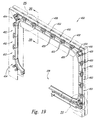
- Figure 19 is an isometric view of a track 450 in accordance with an embodiment of the invention.
- Figure 20 is a partial sectional view of a straight section 452 of the track 450 of Figure 19 taken along line 20-20.
- Figure 21 is an isometric view of a corner section 454 of the track 450 of Figure 19.
- Figure 25 is a partially exploded isometric view of a straight section 452 of the track 450 of Figure 19.
- the track 450 includes a plurality of straight sections 452 and a plurality of corner sections 454. As shown in Figures 19 and 20, each straight section 454 includes a guide support 455 at each end of the straight section 454. A straight slotted cover 456 and a straight backplate 457 are coupled to the straight supports 455 to form a portion of a guide passage 462 that retains the strap 202 during feeding. Each straight slotted cover 456 includes a straight inner surface 472 on the inner circumference of the guide passage 462, and a straight outer surface 474 on the outer circumference of the guide passage 462.
- the straight supports 455 and the corner supports 454 are keyed to fit on a raised "T" section 459 of an outer arch 458.
- the outer arch 458 forms a frame for the other components of the track 450.
- the straight and corner slotted covers 456, 463 open, allowing the strap 202 to pull clear of the guide passage 462.
- Figure 20 illustrates the open position of the slotted cover 456 in phantom to assist in a more complete understanding of the invention.
- each of the straight and corner slotted covers 456, 463 is closed by the springs 461 and becomes ready for the strap 202 to be fed again.
- the V-shape of the guide passage 462 in the corner section 454 helps assure that the strap removal begins in the corner sections 454 rather than in the straight sections 452 of the track 450.
- the V-shape of the guide passage 462 in the corner section 454 causes the track cover 463 to begin opening in the corner section 454.
- the V-shaped guide passage 462 imparts a slight twist to the strap to start opening the straight slotted 456 (see Figure 20) in the straight sections 452 of the track 450.
- each corner section 454 includes a corner slotted cover 463 and a corner backplate 465 coupled to a plurality of guide supports 455.
- the corner slotted cover 463 and corner backplate 465 form a portion of the guide passage 462 therebetween.
- Each corner slotted cover 453 includes a corner inner surface 476 on the inner circumference of the guide passage 462, and a corner outer surface 478 on the outer circumference of the guide passage 462.
- the corner slotted cover 463 and the corner backplate 465 are coupled to the guide supports 455 using a four-bar linkage assembly 469 that permits the corner slotted cover 463 to pivotably open to release the strap 202 from the guide passage 462.
- the inner bars 468 (one shown) of the four-bar linkage assembly 469 have an enlarged opening 470 to permit the corner slotted cover 463 to pivotably open about an axis of rotation that is oriented approximately 45 degrees from the horizontal.
- the straight slotted cover 456 and the straight backplate 457 are spring-loaded by a plurality of springs 461.
- the straight slotted covers 456 and the straight backplates 457 are hingeably engaged on pivot pins 467 that are approximately parallel to the path of the strap 202 in the guide passage 462.
- the pivot pins 467 are inserted through corresponding apertures 467a and 467b in the straight slotted cover 456 and straight backplate 457, respectively, and rotate about an axis defined by the longitudinal axis of the pivot pins 467.
- the pivot pins 467 are retained in position by snap-on retainers or any other convenient retainer element.
- the springs 461 are inserted through a corresponding aperture 461a in the straight backplate 457 and are coupled to the straight slotted cover 456 by a spring retaining pin 466.
- the spring retaining pins 466 are identical to the pivot pins 467 and are retained within corresponding apertures 466a in the straight slotted cover 456 by the snap-on retainers.
- the springs 461 are thus coupled on a proximal end to the straight slotted cover 456 by the spring retaining pins 466 and are retained within the aperture 461 a by an enlarged distal end, sometimes referred to as a circle cotter.
- the straight slotted cover 456 pivot open and release the strap 200 (see Figure 20) and automatically close due to the spring force exerted on the straight slotted cover by the springs 461.
- the guide passage 462 is sized to receive strap sizes varying from approximately 5 mm to approximately 15 mm.
- One advantage of the track 450 of the present invention is the modular construction of the straight and corner sections 452, 454 which allows the track 450 to be incrementally extended in length and height. Because the straight and corner sections 452, 454 are keyed to fit a raised section 459 of the outer arch 458, these components form an easily assembled slide-together arch system, enabling the size of the track 450 to be easily modified for various combinations of length and height. Thus, the size of the strapping station 208 may be quickly and efficiently modified for a variety of bundle sizes.
- each individual straight and corner section 452, 454 may open using only the forces exerted by the strap 202 as it is tightened during tensioning.
- the strap 202 is drawn against the straight inner surfaces 472 and the corner inner surfaces 476, forcing the straight slotted covers 456 and corner slotted covers 463 to pivotably open in the manner described above.
- the track 450 does not require complex hydraulic or pneumatic actuation systems to open the track to release the strap during tensioning. This reduces costs and simplifies maintenance of the track and strapping machine.
- a further advantage of the track 450 is that, shown in Figures 19 through 22, the forces exerted by the strap on the straight slotted covers 456 and corner slotted covers 463 during the feed cycle assist in keeping the track closed during feeding.
- the strap 202 pushes outwardly on the straight outer surfaces 474 and the corner outer surfaces 478 to create a moment ( i.e., a force vector) that forces the straight slotted covers 456 and the corner slotted covers 463 toward the closed position.
- This aspect of the invention reduces misfeeds of the strap, and eliminates the need for complex hydraulic or pneumatic actuation systems to close the track and keep it closed during the feed cycle.
Landscapes
- Engineering & Computer Science (AREA)
- Mechanical Engineering (AREA)
- Basic Packing Technique (AREA)
- Treatment Of Fiber Materials (AREA)
- Coating Apparatus (AREA)
- Apparatus For Radiation Diagnosis (AREA)
- Adhesives Or Adhesive Processes (AREA)
- Surface Acoustic Wave Elements And Circuit Networks Thereof (AREA)
Abstract
Description
- This invention relates to apparatus and methods for applying flexible straps around bundles of objects.
- Many high-speed, automatic strapping machines have been developed, such as those disclosed in U.S. Patent Nos. 3,735,555; 3,884,139; 4,120,239, 4,312,266; 4,196,663; 4,201,127; 3,447,448; 4,387,631; 4,473,005; 4,724,659, 5,379,576, 5,414,980, 5,613,432, and 5,809,873. As disclosed by the devices in these patents, a conveyor belt typically conveys a bundle at high speed to a strapping station where straps are automatically applied before the conveyor belt moves the strapped bundle away from the device.
- Typical strapping machines employ an initial or primary tensioning apparatus that provides an initial tensioning of the strap about the bundle. A secondary tensioning apparatus thereafter provides increased or enhanced tension of the strap. A sealing head then seals the strap, typically through the use of a heated knife mechanism, to complete the bundling operation.
- Of the U.S. Patent, US 5,613,432 A, an arch type strapping machine is known of. The arch type band guide includes corner elements and straight elements, each having the same shape and the same size, wherein the elements are connected in a manner capable of swinging in an arch unit, whereby various sizes of band guide can be easily fabricated depending on the size of articles to be packed.
- Figure 1 is a
strapping machine 100 in accordance with the prior art, as shown and described in U.S. Patent No. 5,414,980, issued to Shibazaki et al. Thestrapping machine 100 includes the following major components, all mounted to a housing or frame 110: astrap dispenser 112, anaccumulator 114, a feed andtension unit 116, atrack 118, a sealinghead 122, and acontrol system 124. In addition. some devices also have a secondary tension unit 120 (not shown), such as the type disclosed in U.S. Patent No. 3,552,305 issued to Domey et al. The basic operation of the machine involves a feeding cycle and a strapping cycle. In the feeding cycle, strap is pulled from a strap coil mounted on thedispenser 112 by a feed and tension motor and is fed through theaccumulator 114, the feed andtension unit 116. the sealinghead 122. and thetrack 118. After the strap has been fed around thetrack 118 and back into the sealinghead 122, the strapping cycle begins. - During the strapping cycle. the strapping machine performs several functions. First, the sealing
head 122 of the strapping machine grips the free end of the strap, holding it securely. Next, in a primary tensioning sequence, a track guide mechanically opens and the strap is pulled from thetrack 118 as the strap is drawn around the bundle by a feed and tension motor. - As the primary tensioning sequence is completed, additional strap tension may be applied by the secondary tension unit 120. As this secondary tensioning process is completed, the sealing
head 122 grips the supply side of the strap. The overlapping strap sections are then heated by a heater blade, pressed together by a press platen, and severed from the supply by a strap cutter 140. - Following the sealing process, the strap path through the sealing
head 122 is once again aligned and the feeding sequence can begin. The sealinghead 122 continues to rotate allowing the seal to cool while the feeding sequence continues. At the end of the strapping cycle, the sealed strap is released and the strappingmachine 100 is ready to repeat the feeding cycle. - Although desirable results are achievable using the prior
art strapping machines 100, some operational drawbacks exist. For example, the prior art feed andtension unit 116 typically includes a complicated series of strap guides. The strap must be fed through the strap guides, undergoing several bends and turns between thedispenser 112 and the sealinghead 122. Existing strapping machines typically turn the strap through a total of 360 degrees or more before reaching the track. The bends and turns in the strap path may induce kinks in the strap that may subsequently lead to feeding difficulties. If the strap becomes jammed in the feed andtension unit 116, the process of clearing the strap path from the complicated series of strap guides may be time-consuming and may require machine downtime. - Another disadvantage of the prior art strapping machines is that the drive assemblies of the sealing
head 122 and the feed and tension unit 120 are typically complicated designs featuring a one or more gear boxes. Often these gear boxes are complicated and must transfer the drive forces through a 90 degree angle. Generally, the cost of fabricating the drive assembly increases with the design complexity, adding to the ultimate cost of the strapping machine. - The present invention improves upon prior strapping devices, and provides additional benefits, such as by providing variability in the apparatus that can be easily altered to fit various production and package requirements and by employing a control system that monitors operating signals and transmits control signals accordingly.
- A feed and tension unit under one aspect of the invention includes three sets of wheels: (1) a feeding set including a feed drive roller and a feed pinch roller, (2) a primary tensioning set including a primary tension drive roller and a primary tension pinch roller, and (3) a secondary tensioning set including a secondary tension drive roller and a secondary tension pinch roller, and wherein at least one of the feed pinch roller, the primary tension pinch roller, or the secondary tension pinch roller is coupled to a solenoid that controllably biases the pinch roller against the respective drive roller based on a pinch signal supplied to the solenoid, the pinch signal having a first pulse width modulated stage that provides a full pinch force and a second pulse width modulated stage that provides a reduced pinch force.
- During a primary tensioning operation, a control system monitors position signals from a feed pinch roller position sensor and terminates primary tensioning when a slippage condition is determined. The control system then initiates a secondary tensioning operation. The secondary tensioning operation lasts for a predetermined amount of time, then the control system initiates a joining operation that secures the strap around the bundle.
- In another aspect of the invention, the three sets of wheels or rollers of the feed and tension unit are configured to provide a simplified strap path that reduces bending of the strap, thereby reducing friction and consequent feeding difficulties. Alternately. the drive wheels of the feed and tension unit may be positioned on the side of the strap opposite from the bundle to reduce adverse effects of debris from the bundle. In another aspect, the feed and tension unit includes inner and outer guides that form a strap channel through the feed and tension unit. The inner and outer guides are configured to provide easy access to the strap path for clearing the strap path in the event of a jam.
- In a further aspect of the invention, a strap material accumulating compartment includes a first sidewall having a plurality of mounting posts projecting therefrom, each mounting post having a plurality of mounting holes disposed therethrough, a second sidewall having a plurality of mounting apertures alignable with and slideably engageable with the mounting posts, and a plurality of pin holders positioned proximate the mounting apertures, and a plurality of mounting pins removably and adjustably engageable with the mounting holes and the pin holders. The first and second sidewalls approximately form a chamber therebetween wherein the strap may accumulate. The width of the chamber may be adjusted easily and quickly to accommodate varying widths of strap by removal of the retaining pins, repositioning the second sidewall at the desired location, and replacement of the retaining pins within the desired holes.
- In yet another aspect of the invention, the track assembly includes a plurality of sections providing modularity of construction. Each section includes a backplate attached to at least one support member, and a slotted cover pivotably attached to the at least one support member proximate the backplate and moveable between an open position spaced apart from the backplate and a closed position proximate the backplate, and a biasing member engaged with the slotted cover that exerts a biasing force on the slotted cover to urge the slotted cover toward the closed position. The biasing force is small enough that a tensioning force in the strap material may overcome the biasing force and thereby actuate the slotted cover toward the open position to allow the strap material to escape from the guide passage during a tension cycle. During a feed cycle, the strap material exerts a closing force on an outer surface of the slotted cover, urging the slotted cover into the closed position. In another aspect, the slotted covers are pivotably mounted on guide pins that are approximately parallel to the path of the strap material within the guide passage.
- In another aspect, a cutting assembly for severing strap material includes a press platen and a cutter having a first cutting blade along a first edge thereof and a second cutting blade along a second edge thereof, the cutter being removably and variably engaged to the press platen such that at least one of the first or second cutting blades is engageable with the strap material. In another aspect, at least one of the first and second edges is slanted at a slant angle with respect to an adjacent edge of the cutter.
- These and other benefits of the present invention will become apparent to those skilled in the art based on the following detailed description.
- Figure 1 is a front elevational view and partial fragmentary view of a strapping machine under the prior art.
- Figure 2 is an isometric view of a strapping machine in accordance with an embodiment of the invention.
- Figure 3 is an isometric view of a sealing head.
- Figure 4 is a top elevational view of the sealing head of Figure 3.
- Figure 5 is a back elevational view of the sealing head of Figure 3.
- Figure 6 is an isometric view of a press platen and a cutter of the sealing head of Figure 3.
- Figure 7 is an isometric view of a main drive assembly.
- Figure 8 is a top elevational view of the main drive assembly of Figure 7.
- Figure 9 is a side elevational view of the main drive the assembly of Figure 7.
- Figure 10 is a first isometric view of a feed and tension unit.
- Figure 11 is a second isometric view of the feed and tension unit of Figure 10.
- Figure 12 is a partial front elevational view of a strap path of the feed and tension unit of Figure 10.
- Figure 13 is a partial isometric view of a primary pinch wheel and a proximity switch of the feed and tension unit of Figure 10.
- Figure 14 is an exploded isometric view of an accumulator.
- Figure 15 is a front elevational view of the accumulator of Figure 14.
- Figure 16 is a top elevational view of the accumulator of Figure 14.
- Figure 17 is an isometric view of a dispenser.
- Figure 18 is a top elevational view of the dispenser of Figure 17.
- Figure 19 is an isometric view of a track.
- Figure 20 is a partial sectional view of a straight section of the track of Figure 19 taken along line 20-20.
- Figure 21 is an isometric view of a corner section of the track of Figure 19.
- Figure 22 is an exploded isometric view of the press platen and cutter of Figure 6.
- Figure 23 is an enlarged partially-exploded isometric view of a pair of inner and outer strap guides of the feed and tension unit of Figure 10.
- Figure 23A is a cross-sectional view of the inner and outer guides of Figure 23 to illustrate the guide slot created by the inner and outer guides.
- Figure 24 is a cross-sectional view of the accumulator of Figure 15 taken along line 24-24.
- Figure 25 is a partially exploded isometric view of a straight section of the track of Figure 19.
- In the drawings, identical reference numbers identify identical or substantially similar elements or steps.
- The present disclosure is directed toward apparatus and methods for strapping bundles of objects.
- Figure 2 is an isometric view of a strapping
machine 200 in accordance with an embodiment of the invention. The strappingmachine 200 includes seven major subassemblies: aframe 210, a control system 220, adispenser 250, anaccumulator 300, a feed andtension unit 350, a sealinghead 400, adrive assembly 500, and atrack 450. The subassemblies are of modular construction, which allows them to be used in multiple frame configurations. - Throughout the following discussion and in the accompanying figures, the strap material is shown and referred to as a particular type of material, namely, a flat, two-sided, tape-shaped strip of material. This practice is adopted herein solely for the purpose of simplifying the description of the inventive methods and apparatus. It should be understood, however, that several of the methods and apparatus disclosed herein may be equally applicable to various types of strap material, and not just to the flat. two-sided, tape-shaped material shown in the figures. Thus, as used herein, the terms "strap" and "strap material" should be understood to include all types of materials used to bundle objects.
- The overall operation of the strapping
machine 200 will first be described with reference to various figures, and thereafter, the individual components will be described in detail. In brief, the operation of the strappingmachine 200 involves paying offstrap 202 from astrap coil 204 located on the dispenser 250 (Figures 17-18), and feeding a free end 206 of thestrap 202 through the accumulator 300 (Figures 14-16), the feed and tension unit 350 (Figures 10-13), the sealing head 400 (Figures 3-5), and around the track 450 (Figures 19-20). After thestrap 202 is fed around thetrack 450, the free end 206 is fed back into the sealinghead 400. At this point thestrap 202 is in position to start a strapping cycle. - Upon the start of the strapping cycle, several sealing
head cams 402 in the sealing head 400 (Figures 3-5) begin to rotate, forcing a left-hand gripper 404 to pinch the free end 206 of thestrap 202 against ananvil 406. After gripping thestrap 202 in the sealinghead 400, the feed and tension unit 350 (Figures 10-13) retracts thestrap 202 from thetrack 450. As thestrap 202 is pulled from thetrack 450, thestrap 202 is tensioned around a bundle of objects (not shown) located in a strapping station 208 (Figure 2) by a feed and tension motor 361 (Figure 10). As thestrap 202 becomes tight around the bundle, a primary tension pinch wheel 352 (Figure 10) stops rotating. A proximity sensor 354 (Figure 11) detects the lack of rotation of the primary tension pinch wheel 352 (Figure 12) and starts a secondary tension process. - Preferably, the
cams 402 operate as cycloidal cams allowing the sealinghead 400 to operate smoothly at increased speeds and the cam follower pressure angles are minimized to extend cam life. As used herein, the term cycloidal cam means a cam with cycloidal displacement generated by taking a sinusoidal acceleration function that has a magnitude of zero at its beginning and end, and integrating the function to obtain the velocity and displacement of the follower. - Secondary tension is applied until a drive wheel clutch 356 (Figures 7-8) slips, at a predetermined set-point, and the sealing
head 400 rotates far enough to grip thestrap 202 with a right-hand gripper 408. After thestrap 202 is gripped by the right-hand gripper 408, the tension on the free end 206 of thestrap 202 is released and thestrap 202 around the bundle is cut free from thecoil 204 by a cutter 414 (Figures 3 and 6). The two overlapping ends of thestrap 202 are then heated by inserting a heater blade 410 (Figure 3) between them and lightly pressing the straps against theblade 410 with a press platen 412 (Figure 3). Thepress platen 412 then lowers slightly and theheater blade 410 is removed from between the strap ends. Next, thepress platen 412 presses both ends against the anvil 406 (Figure 3) for bonding and cooling. As the sealinghead cams 402 continue to rotate, thepress platen 412 lowers slightly allowing theanvil 406 to open and release the sealed strap. After the strap is released, theanvil 406 is closed and the strapping cycle is completed by feedingstrap 202 through the sealinghead 400, around thetrack 450, back into the sealinghead 400 and finally actuating a feed stop switch 416 (Figure 3). - Two modes of operation are available: manual and automatic. The manual mode applies single or multiple straps while an operator actuates a switch. The automatic mode applies a single strap or multiple straps when a switch is actuated by a moving bundle. The automatic mode is used in conveyor lines and in conjunction with other automated machinery.
- As shown in Figure 2, the
frame 210 consists of amain support 212,adjustable legs 214, and coverplates 216. Theframe 210 provides structural support for all of the other sub-assemblies of the strappingmachine 200. In this view, thestrap 202 is fed about thetrack 450 in a strap-feed direction 209 that is generally counterclockwise. - The strapping
machine 200 is controlled by a control system 220 that may include a programmable logic controller 222 (Figure 3) that operates in conjunction with various input and output devices and controls the major subassemblies of the strappingmachine 200. Input devices may include, for example, momentary and maintained push buttons, selector switches, toggle switches, limit switches and inductive proximity sensors. Output devices may include, for example, solid state and general purpose relays, solenoids, and indicator lights. Input devices are scanned by thecontroller 222, and their on/off states are updated in acontroller program 224. Thecontroller 222 executes thecontroller program 224 and updates the status of the output devices accordingly. Other control functions of thecontroller 222 are described below in further detail. - In one embodiment the
programmable controller 222 and its associated input and output devices may be powered using a 24 VDC power supply. Thecontroller 222, power supply, relays, and fuses may be contained within a control panel (not shown). The momentary and maintained push buttons, selector switches, and toggle switches may be located on a control pendant or a control panel cover. The limit switches, inductive proximity sensors, and solenoids are typically located within the strappingmachine 200 at their point of use. At least one indicator light may be mounted on the top of thetrack 450 and may light steadily to indicate an out-of-strap condition, and may flash to indicate a strap misfeed condition. - One commercially-available
programmable controller 222 suitable for use with the strappingmachine 200 is the T100MD1616+ PLC manufactured by Triangle Research International Pte Ltd in Singapore. This device includes sixteen NPN-type digital outputs, four of which are NPN Darlington Power Transistor types and twelve of which are N-channel power MOSFET types. Two of the outputs are capable of generating a Pulse Width Modulated (PWM) signal with a frequency and duty cycle determined in the programming software. Also included are four input channels of 10-bit analog-to-digital converters. Two of the input channels are buffered by operational amplifiers with a x5 gain accepting analog signals of 0-1V full scale. The remaining two channels are unbuffered and accept 0-5V full scale analog signals. The unit includes a stable 5V (+/- 1% accuracy) regulated DC power supply to be used as a voltage reference for the analog inputs. A single channel 8-bit digital-to-analog output utilizing a 0-20mA current loop signal, also resides on the PLC. - The T100MD1616+ PLC has communication ports, including an RS232C port for program uploads, downloads and monitoring, a two-wire RS485 network port, a 14-pin LCD display port for possible future use as a diagnostic display driver, and a port for expansion. The PLC itself is controlled by a custom CPU that has both EEPROM and RAM memory backup. The
controller program 224 used to program thecontroller 222 may, for example, include Trilogi programming software available from Triangle Research International Pte Ltd, and may include both ladder logic and Tbasic type code (described more fully at www.tri.com.sg/index.htm). - Figure 3 is an isometric view of the sealing
head 400 of the strappingmachine 200 of Figure 2. Figures 4 and 5 are top elevational and back elevational views, respectively, of the sealinghead 400 of Figure 3. Figure 6 is an isometric view of thepress platen 412 and thecutter 414 of the sealinghead 400 of Figure 3. The sealinghead 400 comprises a motor-drivenmain shaft 418 and a series ofcams 402 which perform gripping, sealing and cutting functions. Thesecams 402 drive three slidingmembers 422 and three rotating arms 424 (Figure 5). Oneslide member 422 is coupled to the right-hand gripper 408, anotherslide member 422 is coupled to the left-hand gripper 404, and thethird slide member 422 is coupled to thepress platen 412. The slidingmembers 422 perform the gripping, sealing and cutting functions, while the pivotingarms 424 move aninner slide 420, theanvil 406, and theheater blade 410 into and out of a strap path as required during a strapping cycle. - Figure 22 is an exploded isometric view of the
press platen 412 andcutter 414 of Figure 6. As shown in this view, thepress platen 412 includes a pair of mountingnubs 411, and thecutter 414 includes mounting recesses 413. Aspring 415 is disposed between thecutter 414 and thepress platen 412, one end of thespring 415 being partially disposed within aseating hole 417 disposed in thepress platen 412. Thecutter 414 has cuttingedges 419 at both ends, allowing thecutter 414 to be reversibly positioned on thepress platen 412 for added operational life. In the embodiment shown in Figure 22, the cuttingedges 419 are slanted at an angle α. Although a wide variety of cutting edge angles α may be used, a cutting edge angle in the range of approximately 9 degrees or less is preferred. - During assembly, the
spring 415 is compressed between thecutter 414 and thepress platen 412 until the two mountingrecesses 413 slideably engage two of the mountingnubs 411. One may note that thecutter 414 has a pair of mountingrecesses 413 situated near each end of thecutter 414 which allows thecutter 414 to be reversibly mounted onto thepress platen 412. Thecutter 414 and thepress platen 412 are then positioned securely between the left and right-hand grippers spring 415. Thecutter 414 andpress platen 412 are then engaged with thethird slide member 422. This arrangement provides the necessary scissors action to sever thestrap 202. - An advantage of the
cutter 414 andpress platen 412 assembly shown in Figures 6 and 22 is that thecutter 414 is removably and replaceably mounted to thepress platen 412 by slideably engaging onto thepress platen 412. This allows thecutter 414 to be more easily removed for replacement or maintenance than in the prior art devices. The reversibility of thecutter 414 also essentially doubles the useful life of the component. - Figure 7 is an isometric view of a
main drive assembly 500. Figures 8 and 9 are top and side elevational views, respectively, of themain drive assembly 500 of Figure 7. Themain drive assembly 500 includes amain drive motor 502 that drives a sealing head drive belt, 508 and adrive wheel belt 510. The sealinghead drive belt 508 and thedrive wheel belt 510 are preferably "toothed" belts. The sealinghead drive belt 508 is directly coupled to aspring clutch 504. Thedrive wheel belt 510 is turned approximately 90 degrees on a pair of drive pulleys 512 and is coupled to thedrive wheel clutch 356. As shown in Figure 7, themain drive motor 502, thespring clutch 504, and thedrive wheel clutch 356 are operatively coupled to thecontroller 222, such as, for example, by electrically conductive leads 223. - One advantage of the
main drive assembly 500 is that thedrive wheel clutch 356 is driven by thedrive wheel belt 510, which is turned at an approximately 90 degree angle on the drive pulleys 512. This arrangement. commonly referred to as a "mule drive," eliminates a 90-degree gearbox commonly found in drive systems of prior art strapping machines. Thus, the complexity and costs of fabrication of themain drive assembly 500 are reduced, and reliability and maintainability is improved. - In the accompanying figures, the
spring clutch 504 is a wrap spring clutch and thedrive wheel clutch 356 is an electromagnetic clutch. Alternately,other spring clutch 504 and drive wheel clutch 356 embodiments may be used. Thespring clutch 504 stops the sealinghead cams 402 at the proper degree of rotation during each stage of the cycle and stops thecams 402 in their home position at the end of each cycle. As stated above, the drive wheel clutch 356 slips at a torque that is determined by the voltage supplied to a coil located within the electromagneticdrive wheel clutch 356. The slip in thedrive wheel clutch 356 determines the amount of secondary tension that is applied to thestrap 202. - The
main drive motor 502 drives the sealinghead 400 by means of the sealinghead drive belt 508 and the spring clutch 504 (Figures 7 and 8) which is mounted over an end of the sealing head main shaft 418 (Figure 3). Rotation of themain shaft 418 causes the keyed cams 402 (Figures 3 and 5) to rotate and perform the necessary gripping, sealing and cutting functions. During a first period of rotation, themain shaft 418 rotates to the first of three stops on thespring clutch 504, causing a cutter-gripper assembly 426 to grip thestrap 202 and theinner slide 420 to move out of the strap path. Themain drive motor 502 then tensions the strap about the bundle, as will be described more fully below. When the strap tensioning is complete, thecontroller 222 pulses thespring clutch 504 allowing thecams 402 to rotate in a second period of rotation. - During the second period of rotation the right-
hand gripper 404 grips the tensioned strap just ahead of thefeed stop switch 416 and the tension in the strap is then released. After the tension is released, theplaten 412 and the cutter 414 (Figures 6 and 22) rise to cut thestrap 202 and press the strap against theheater blade 410. Thecams 402 continue to rotate through a dwell section as thestrap 202 melts on theheater blade 410. After a predetermined time for melting has passed, thepress platen 412 and thecutter 414 retract slightly allowing theheater blade 410 to retract. - After the
heater blade 410 retracts, thepress platen 412 rises again to press the two melted ends of thestrap 202 together for cooling and sealing. The sealing headmain shaft 418 continues to rotate during a third period of rotation until a clutch trigger 428 disengages thespring clutch 504. The sealinghead 400 maintains this position for a predetermined time until thecontroller 222 again energizes a spring clutch solenoid 506 (not shown) located within thespring clutch 504. The continued rotation of thecams 402 releases thepress platen 412 and drops the left and right-hand grippers cams 402 then pivots theanvil 406 out of the strap line past a pair ofstrippers 430. As theanvil 406 pivots, thestrippers 430 push the strap off of theanvil 406. After thestrap 202 is out of the sealinghead 400, theanvil 406 closes, and thecams 402 reach their home positions. At the home position thespring clutch 504 reaches the third and final stop as the feed stop switch 416 (Figure 3) signals thecontroller 222 to begin another feed sequence. - Figure 10 is a first isometric view of the feed and
tension unit 350. Figures 11 and 12 are a second isometric view and a partial front elevational view, respectively, of the feed andtension unit 350 of Figure 10. As best seen in Figure 12, there are three sets of wheels in the feed and tension unit 350: (1) a primary tensioning set including a primarytension drive wheel 360 and a primarytension pinch wheel 352, (2) a secondary tensioning set including a secondarytension drive wheel 362 and a secondarytension pinch wheel 364, and (3) a feeding set including afeed drive wheel 366 and afeed pinch wheel 368. - The feed and
tension unit 350 pinches thestrap 202 between each of the three sets of drive wheels and pinch wheels. The feed, primary tension, and secondarytension pinch wheels strap 202 by afeed pinch solenoid 370a, a primarytension pinch solenoid 370b, and a secondarytension pinch solenoid 370c, respectively. Thedrive wheel clutch 356 is powered by adrive wheel belt 510 from themain drive motor 502. The primary tension and feeddrive wheels secondary drive belt 372 mounted on a feed andtension motor 361. The secondarytension drive wheel 362 is powered by the drive wheel clutch 356 that is driven by thedrive wheel belt 510 from themain drive motor 502. As shown in Figures 10 and 11, the feed andtension motor 361, and thesolenoids controller 222 by conductive leads 223. - Unlike prior art strapping machines which feed the strap around several bends in the feed and tension unit prior to reaching the track, the strapping
machine 200 features a simplified strap path (Figure 12) allowing the strap to be red in a straighter path than previously achievable. The path begins at thesupply dispenser 250 that is located on the opposite side of the strapping machine from the feed and tension unit. This position further enables the strap to travel in a less tortuous path. As shown in Figure 12, thedrive wheels strap 202 traversing an approximately "V-shaped" strap path having an included angle of in the range of approximately 20 degrees to approximately 40 degrees. Less bending of the strap reduces friction throughout the system, increasing the reliability of strap feeding. Less bending also reduces the tendency of the strap to permanently deform and cause feeding difficulties. Thus, the feed andtension unit 350 of the present invention advantageously reduces or eliminates kinks in the strap which lead to feeding difficulties. While the strapping machines of the prior art typically turned the strap through a total of 360 degrees or more prior to reaching the track, the feed andtension unit 350 greatly reduces the amount of turning of the strap. For example, in the embodiment shown in the accompanying figures, the strap is turned through between approximately 180 and approximately 220 degrees as the strap is initially fed from thedispenser 250 across the strapping machine to the sealinghead 400. - As the
strap 202 passes through each set of pinch wheels, a plurality ofinner guides 374 and a plurality ofouter guides 376 keep thestrap 202 in line with the sealinghead 400. Figure 23 is an enlarged partially-exploded isometric view of a pair of inner and outer strap guides 374, 376 of the feed andtension unit 350 of Figure 10. As best viewed in Figure 23, each "L-shaped"inner guide 374 has a roughly L-shaped cross-section and is coupled to a matching "L-shaped"outer guide 376 to form astrap channel 380 through which thestrap 202 passes. Figure 23A is a cross-sectional view of theinner guide 374 andouter guide 376 and illustrates the guide chamber formed by the inner and outer guides to guide thestrap material 202. - The inner and
outer guides tension unit 350 by a plurality of retainingknobs 379, although a variety of other securing devices may be used. In Figure 10, one of theouter guides 376 is removed from the strap path adjacent to the primary tension pinch and drivewheels - During a feeding sequence, the
strap 202 is pinched between the feed drive and pinchwheels wheels solenoid 370a in two stages: a first stage that provides a full feed force and a second stage that provides a reduced feed force by altering the pulse width modulation of thefeed pinch solenoid 370a. Because the pinch force exerted by asolenoid 370a on thestrap 202 varies with supplied voltage, supplying a pulse width modulated voltage signal to thesolenoid 370a provides the ability to vary the force exerted by thesolenoid 370a. As the force exerted by thesolenoid 370a is decreased, thestrap 202 is permitted to slip on thefeed drive wheel 366 more easily with a decreased amount of feed drive force. Commercially-available solenoids suitable for this purpose include those solenoids available from Ledex® Actuation Products of Vandalia, Ohio. - It should be noted that the frequency of the pulses which are fed to the solenoid affects the operation and performance of the solenoid. Generally, as the frequency of the pulses is increased, the adjustability of the pinch force exerted by the solenoid is improved. For example, using the above-referenced solenoids available from Ledex® Actuation Products, a pulse frequency of 8000 Hz has been successfully used.
- The feed drive and pinch
wheels head 400, around thetrack 450, and back into the sealinghead 400. When the free end 206 of thestrap 202 reaches the sealinghead 400, the arrival of the free end 206 is detected byfeed stop switch 416, which transmits a feed stop signal to thecontroller 222. Thecontroller 222 then sends a feed pinch signal to thefeed pinch wheel 368 to disengage thefeed pinch wheel 368 from thestrap 202, and the feeding sequence is complete. - During a primary tensioning sequence, the
strap 202 is pinched between the primarytension drive wheel 360 and the primarytension pinch wheel 352. In a first primary tension stage, theprimary tension solenoid 370b engages the primarytension pinch wheel 352 against the primarytension drive wheel 360 with full pinch force to ensure that the primary tensioning solenoid engages and thestrap 202 is pulled free of thetrack 450. The pinch force is then reduced during a second primary tension stage by altering the pulse width modulation of theprimary tension solenoid 370b. As thestrap 202 is pulled tightly around the bundle during the primary tensioning sequence, the primarytension pinch wheel 352 stops rotating due to the slippage of the strap on the primarytensioning drive wheel 360. - Using pulse width modulation to control the pinch forces exerted by the
solenoids strap 202 movement, including allowing thestrap 202 to be quickly accelerated and to be easily stopped as required by the operator. - Figure 13 is an isometric view of the primary
tension pinch wheel 352 and theproximity sensor 354 of the feed andtension unit 350 of Figure 10. Theproximity sensor 354 is operatively coupled to thecontroller 222. Theproximity sensor 354 monitors the primarytension pinch wheel 352 during primary tensioning, such as by monitoring the passing of notches in thewheel 352, to detect the stall of the primarytension pinch wheel 352. Theproximity sensor 354 transmits signals to thecontroller 222. As the signals from theproximity sensor 354 indicate that the primarytension pinch wheel 352 is not turning due to the slippage of thestrap 202 on the primarytension drive wheel 360, thecontroller 222 starts a secondary tensioning sequence. - The secondary tensioning sequence begins by pinching the strap between the secondary
tension pinch wheel 364 and the secondarytension drive wheel 362. Then, the secondarytension drive wheel 362 is driven by thedrive wheel clutch 356 until the drive wheel clutch 356 starts to slip. After thestrap 202 is tensioned to the point that the drive wheel clutch 356 slips, thecontroller 222 permits a predetermined amount of time to pass to allow the strap to be cut and sealed as described above. The feeding sequence may then be repeated. - An advantage of the strapping
machine 200 is that thepinch wheels solenoids machine 200 operation. During the first stage, the solenoid is given a PWM signal at a constant duty cycle. For the second stage, the solenoid is controlled using a PWM signal with a duty cycle that is user-adjustable via, for example, a potentiometer. Since the average voltage seen by the solenoid is determined by the duty cycle, varying the duty cycle will vary the amount of force the solenoid pulls. Thus, thepinch wheels machine 200, eliminating the labor-intensive process of mechanical re-adjustment of thepinch wheels - Figure 14 is an exploded isometric view of an
accumulator 300. Figures 15 and 16 are front and top elevational views, respectively, of theaccumulator 300 of Figure 15 taken along line 24-24. Theaccumulator 300 includes first andsecond sidewalls chamber 306 that stores strap for rapid feeding, as well as for temporarily storing of thestrap 202 that is drawn back in the tensioning process. Thesecond sidewall 304 is incrementally adjustable by placing retainingpins 308 in a series ofholes 310 located inshafts 312 that protrude from thefirst sidewall 302 to accommodate different sizes ofstrap 202.Pin holders 309 are attached to thesecond sidewall 304 which engage the retaining pins 308 and fix the position of thesecond sidewall 304 on theshafts 312. - The
chamber 306 is substantially enclosed by thefirst sidewall 302 and the adjustablesecond sidewall 304. A pair ofendwalls 320 extend vertically between the first and second sidewalls 302,304. Atop wall 322 extends horizontally along between the first and second sidewalls 302,304, thetop wall 322 having thetop entrance 316 wherestrap 202 is fed into and pulled out of theaccumulator unit 300. An "L" shapedwand 324 extends between the first and second sidewalls 302,304 along the bottom of thechamber 306. Thewand 324 is pivotally attached to thefirst sidewall 302. - In operation, an accumulator motor 330 (Figure 14) drives an
accumulator drive wheel 332 to feed thestrap 202 between theaccumulator drive wheel 332 and anaccumulator pinch wheel 334. An accumulator feed switch 336 (Figure 14) is positioned proximate the accumulator drive and pinch wheels 332,334 to detect the presence of thestrap 202 and to transmit a control signal to theaccumulator motor 330. As thechamber 306 fills withstrap 202, thewand 324 is pushed downwardly by the weight of thestrap 202, pivoting thewand 324 into contact with an indicator switch 326 (Figure 15). Theindicator switch 326 then transmits a signal to thecontroller 222 to shut off theaccumulator motor 330, as described more fully below. - Alternately, during an automatic feeding mode, a
strap diverter 314 covers atop entrance 316 of thechamber 306. Whenstrap 202 is fed into the strappingmachine 200 by theaccumulator motor 330, a diverter solenoid 318 (Figure 14) pulls thestrap diverter 314 over thetop entrance 316 of thechamber 306, diverting thestrap 202 directly into the feed andtension unit 350 and around thetrack 450. - As best seen in Figure 24, the
accumulator 300 advantageously allows the width w of thechamber 306 and thetop entrance 316 to be adjusted easily and quickly to accommodate varying widths ofstrap 202. Unlike prior art apparatus that have accumulator sidewalls that are solidly affixed to form a single chamber size, theaccumulator 300 of the present invention includesshafts 312 having a plurality ofholes 310 placed at increments to match various commonly used strap sizes. Thus, the position of thesecond sidewall 304 with respect to thefirst sidewall 302 may be quickly and easily varied by removal of the retaining pins 308, repositioning thesecond sidewall 304 at the desired location, and replacement of the retaining pins 308 within the desired holes 310. Thepin holders 309 then engage against the retainingpins 308 and fix the position of thesecond sidewall 304 on theshafts 312. This mounting configuration allows the adjustment of the accumulator without having any additional parts, such as spacers between the first andsecond sidewalls - Figure 17 is an isometric view of a
dispenser 250. Figure 18 is a top elevational view of thedispenser 250 of Figure 17. Thedispenser 250 includes a mountingshaft 252 extending outwardly from theframe 210 between aninner hub 254 and anouter hub 256. Aspring brake 258 is operatively coupled to the mountingshaft 252 and to theframe 210. When actuated, thebrake 258 allows the rotation of the mountingshaft 252. A mandrel 260 is rotatably mounted on the mountingshaft 252 and supports theinner hub 254 and theouter hub 256.Strap 202 is routed from thestrap coil 204 around afirst pulley 262 and asecond pulley 264 and over astrap exhaust switch 266. - As
strap 202 is required in theaccumulator 300, theaccumulator motor 330 is energized and thedispenser brake 258 released, allowing thestrap coil 204 to spin freely andstrap 202 to feed into thechamber 306. In this embodiment, thebrake 258 releases thestrap coil 204 to spin only when power is supplied to thebrake 258. When thestrap coil 204 is depleted, thestrap exhaust switch 266 is no longer actuated which stops the strappingmachine 200 until thestrap coil 204 is replenished. A braking circuit is used to prevent theaccumulator motor 330 from drawing the free end 206 of the strap into theaccumulator 300. The remaining loose tail of strap can then be pulled out of theaccumulator 300 before a new strap coil is installed. Theempty strap coil 204 is replaced by removing an outerhub securing nut 268 and theouter hub 256, and then removing the strap coil core (not shown) from the mandrel 260. Next, afresh strap coil 204 is placed on the mandrel 260 with thestrap 202 wound in a clockwise direction. Finally, theouter hub 256 and the outerhub securing nut 268 are replaced and the nut tightened securely. - To begin feeding the
strap 202, the free end 206 is removed from thestrap coil 204, threaded around thefirst pulley 262, through thestrap exhaust switch 266, around thesecond pulley 264 and between theaccumulator drive wheel 332 and theaccumulator pinch wheel 334. As thestrap 202 is placed between theaccumulator wheels accumulator feed switch 336 is actuated causing the accumulator feed solenoid to actuate, thus feeding the strap over the accumulator and into the track. - When enough force is applied to the
wand 324 by the weight of thestrap 202 accumulating in thechamber 306, thewand 324 moves downwardly to actuate theindicator switch 326, indicating that theaccumulator unit 300 is full. In response to this signal, thecontroller 222 de-energizes the accumulator motor 328 and thedispenser brake 330 to halt the accumulator filling sequence. A time delay occurs between when thedispenser brake 330 is de-energized and when the accumulator motor 328 is de-energized to take up any slack in thestrap coil 204. - Figure 19 is an isometric view of a
track 450 in accordance with an embodiment of the invention. Figure 20 is a partial sectional view of astraight section 452 of thetrack 450 of Figure 19 taken along line 20-20. Figure 21 is an isometric view of acorner section 454 of thetrack 450 of Figure 19. Figure 25 is a partially exploded isometric view of astraight section 452 of thetrack 450 of Figure 19. During feeding, after thestrap 202 exits from the sealinghead 400, it is pushed completely around thetrack 450 and then back into the sealinghead 400. Thetrack 450 directs thestrap 202 around the strappingstation 208. - The
track 450 includes a plurality ofstraight sections 452 and a plurality ofcorner sections 454. As shown in Figures 19 and 20, eachstraight section 454 includes aguide support 455 at each end of thestraight section 454. A straight slottedcover 456 and astraight backplate 457 are coupled to thestraight supports 455 to form a portion of aguide passage 462 that retains thestrap 202 during feeding. Each straight slottedcover 456 includes a straightinner surface 472 on the inner circumference of theguide passage 462, and a straightouter surface 474 on the outer circumference of theguide passage 462. - As best seen in Figures 20 and 21, the
straight supports 455 and the corner supports 454 are keyed to fit on a raised "T"section 459 of anouter arch 458. Theouter arch 458 forms a frame for the other components of thetrack 450. As thestrap 200 is tensioned around the bundle, the straight and corner slottedcovers strap 202 to pull clear of theguide passage 462. Figure 20 illustrates the open position of the slottedcover 456 in phantom to assist in a more complete understanding of the invention. As thestrap 202 clears theguide passage 462, each of the straight and corner slottedcovers springs 461 and becomes ready for thestrap 202 to be fed again. The V-shape of theguide passage 462 in thecorner section 454 helps assure that the strap removal begins in thecorner sections 454 rather than in thestraight sections 452 of thetrack 450. When the strap 202 (see Figure 20) is removed from thetrack 450, the V-shape of theguide passage 462 in thecorner section 454 causes thetrack cover 463 to begin opening in thecorner section 454. As thestrap 202 begins to separate from thetrack 450 in thecorner sections 454, the V-shapedguide passage 462 imparts a slight twist to the strap to start opening the straight slotted 456 (see Figure 20) in thestraight sections 452 of thetrack 450. - As shown in Figure 21, each
corner section 454 includes a corner slottedcover 463 and acorner backplate 465 coupled to a plurality of guide supports 455. The corner slottedcover 463 andcorner backplate 465 form a portion of theguide passage 462 therebetween. Each corner slotted cover 453 includes a cornerinner surface 476 on the inner circumference of theguide passage 462, and a cornerouter surface 478 on the outer circumference of theguide passage 462. In this embodiment, the corner slottedcover 463 and thecorner backplate 465 are coupled to the guide supports 455 using a four-bar linkage assembly 469 that permits the corner slottedcover 463 to pivotably open to release thestrap 202 from theguide passage 462. Although alternate embodiments for pivotably mounting the corner slottedcovers 463 may be conceived, in the embodiment shown in Figure 21, the inner bars 468 (one shown) of the four-bar linkage assembly 469 have anenlarged opening 470 to permit the corner slottedcover 463 to pivotably open about an axis of rotation that is oriented approximately 45 degrees from the horizontal. - As best shown in Figure 25, the straight slotted
cover 456 and thestraight backplate 457 are spring-loaded by a plurality ofsprings 461. The straight slottedcovers 456 and thestraight backplates 457 are hingeably engaged onpivot pins 467 that are approximately parallel to the path of thestrap 202 in theguide passage 462. The pivot pins 467 are inserted throughcorresponding apertures cover 456 andstraight backplate 457, respectively, and rotate about an axis defined by the longitudinal axis of the pivot pins 467. The pivot pins 467 are retained in position by snap-on retainers or any other convenient retainer element. - The
springs 461 are inserted through a correspondingaperture 461a in thestraight backplate 457 and are coupled to the straight slottedcover 456 by aspring retaining pin 466. In an exemplary embodiment, the spring retaining pins 466 are identical to the pivot pins 467 and are retained within correspondingapertures 466a in the straight slottedcover 456 by the snap-on retainers. Thesprings 461 are thus coupled on a proximal end to the straight slottedcover 456 by the spring retaining pins 466 and are retained within theaperture 461 a by an enlarged distal end, sometimes referred to as a circle cotter. This arrangement allows the straight slottedcover 456 to pivot open and release the strap 200 (see Figure 20) and automatically close due to the spring force exerted on the straight slotted cover by thesprings 461. Although various sizes of straight slotted covers 456 may be employed, in the embodiment shown in Figures 20 and 25, theguide passage 462 is sized to receive strap sizes varying from approximately 5 mm to approximately 15 mm. - One advantage of the
track 450 of the present invention is the modular construction of the straight andcorner sections track 450 to be incrementally extended in length and height. Because the straight andcorner sections section 459 of theouter arch 458, these components form an easily assembled slide-together arch system, enabling the size of thetrack 450 to be easily modified for various combinations of length and height. Thus, the size of the strappingstation 208 may be quickly and efficiently modified for a variety of bundle sizes. - Another advantage of the
track 450 is that by pivoting the straight slottedcovers 456 parallel to the strap path, and by pivoting the corner slottedcovers 463 on the four-bar linkage assemblies 469, each individual straight andcorner section strap 202 as it is tightened during tensioning. During the tension cycle, thestrap 202 is drawn against the straightinner surfaces 472 and the cornerinner surfaces 476, forcing the straight slottedcovers 456 and corner slottedcovers 463 to pivotably open in the manner described above. Thus, thetrack 450 does not require complex hydraulic or pneumatic actuation systems to open the track to release the strap during tensioning. This reduces costs and simplifies maintenance of the track and strapping machine. - A further advantage of the
track 450 is that, shown in Figures 19 through 22, the forces exerted by the strap on the straight slottedcovers 456 and corner slottedcovers 463 during the feed cycle assist in keeping the track closed during feeding. During the feed cycle. thestrap 202 pushes outwardly on the straightouter surfaces 474 and the cornerouter surfaces 478 to create a moment (i.e., a force vector) that forces the straight slottedcovers 456 and the corner slottedcovers 463 toward the closed position. This aspect of the invention reduces misfeeds of the strap, and eliminates the need for complex hydraulic or pneumatic actuation systems to close the track and keep it closed during the feed cycle.
Claims (17)
- An apparatus (200) for bundling one or more objects with a strap material (202), comprising:a track assembly (450) for releasably receiving and guiding the strap material (202), the track assembly (450) having a backplate (457) attached to a support member (455) and characterized by:a slotted cover (456) pivotably attached to the support member (455), the slotted cover (456) being moveable between an open position spaced apart from the backplate (457) and a closed position proximate the backplate (457); anda biasing member (461) such as a spring engaged with the slotted cover (456) to exert a biasing force on the slotted cover (456) to urge the slotted cover (456) toward the closed position, the track assembly (450) having a guide passage (462) sized to receive the strapping material (202), wherein the biasing force is small enough that a tensioning force in the strap material (202) will overcome the biasing force to actuate the slotted cover (456) toward the open position to allow the strap material (202) to escape from the guide passage (462).
- The apparatus of claim 1 wherein the track assembly (450) comprises a plurality of track sections, each of the track sections having the slotted cover (456) and biasing member (461).
- The apparatus of claim 2 wherein the plurality of track sections comprise a plurality of straight sections (452) and a plurality of corner sections (454).
- The apparatus of claim 3 wherein the guide passage of the corner sections (454) is V-shaped to permit initial opening of the slotted cover (456) at the corner sections (454).
- The apparatus of any of the preceding claims 3 or 4 wherein the cover (456) of at least one straight track section (452) is pivotally attached to the support member (455) using a pivot pin (467), the pivot pin (467) having a lengthwise axis that is approximately parallel to the direction of movement of the strap material (202) through the slot (462) to thereby permit the cover (456) to pivot on the axis of rotation substantially parallel to the direction of movement of the strap material (202) through the guide passage (462).
- The apparatus of any of the preceding claims 3 to 5 wherein the cover (456) of at least one corner track section (454) is pivotally attached to the support member (455) using a four-bar linkage.
- The apparatus of any of the preceding claims 1 to 6 wherein the slotted cover (456) is pivotably attached to the at least one support member (455) using a pivot pin (467), the pivot pin (467) having a lengthwise axis that is approximately parallel to the guide passage.
- The apparatus of any of the preceding claims 1 to 7 wherein the slotted cover (456) includes a slot having an inner surface (472) and an outer surface (474), the strap material (202) exerting the tensioning force on the inner surface (472) during a tension cycle and exerting a closing force on the outer surface (474) during a feed cycle.
- The apparatus of any of the preceding claims 1 to 8 wherein the guide passage (462) is formed by the slotted cover (456).
- The apparatus of any of the preceding claims 1 to 9, further comprising at least one outer support, wherein the at least one support member (455) is slideably engaged on a raised portion of the outer support.
- A method for bundling one or more objects with a strap material (202) using a track assembly (450) according to claim 1 for releasably receiving and guiding the strap material (202), comprising:receiving and guiding the strapping material (202) around the track assembly (450);pivoting a slotted cover (456) between an open position and a closed position;exerting a biasing force on the slotted cover (456) to urge the slotted cover (456) toward the closed position to retain the strapping material (202) within a guide passage (462) sized to receive the strapping material (202); andapplying a tensioning force to the strapping material (202), the tensioning force being sufficient to overcome the biasing force to actuate the slotted cover (456) toward the open position to allow the strap material (202) to escape from the guide passage (462).
- The method of claim 11 wherein the track assembly comprises a plurality of track sections, receiving and guiding the strapping material comprising receiving and guiding the strapping material in each of the track sections, pivoting comprises pivoting a cover member on each of the track sections, exerting a biasing force comprises exerting a biasing force on the slotted cover (456) of each of the track sections and applying the tensioning force to the strapping material (202) comprises overcoming the biasing force to actuate the slotted cover (456) of each of the track sections.
- The method of claim 12 wherein the plurality of track sections comprise a plurality of straight sections (452) and a plurality of corner sections (454) and tensioning the strapping material (202) causes the slotted cover (456) of the corner sections to open before the slotted cover (456) of the straight sections (452).
- The method of claim 13 wherein the plurality of track sections comprise a plurality of straight sections (452) and a plurality of corner sections (454) and pivoting the cover (456) of at least one straight track section (452) comprises pivoting the cover (456) on an axis of rotation substantially parallel to the direction of movement of the strap material (202) through the guide passage (462).
- The method of any of the preceding claims 13 to 14 wherein the cover (456) of at least one corner track section is pivotally attached to the support member using a four-bar linkage and pivoting the cover (456) comprises pivoting about an axis of rotation that is approximately 45° from the horizontal.
- The method of any of the preceding claims 11 to 15 wherein the slotted cover (456) includes a slot having an inner surface (472) and an outer surface (474) and tensioning comprises exerting the tensioning force on the inner surface during a tension cycle, the method further comprising exerting a closing force on the outer surface during a feed cycle.
- The method of any of the preceding claims 11 to 16 wherein the guide passage (462) is formed by the slotted cover (456) and receiving and guiding the strapping material (202) comprises receiving and guiding the strapping material (202) through the slotted cover (456).
Applications Claiming Priority (3)
| Application Number | Priority Date | Filing Date | Title |
|---|---|---|---|
| US09/454,912 US6415712B1 (en) | 1999-12-02 | 1999-12-02 | Track mechansim for guiding flexible straps around bundles of objects |
| US454912 | 1999-12-02 | ||
| PCT/US2000/032320 WO2001040053A2 (en) | 1999-12-02 | 2000-11-22 | Apparatus and methods for applying flexible straps around bundles of objects |
Publications (2)
| Publication Number | Publication Date |
|---|---|
| EP1265786A2 EP1265786A2 (en) | 2002-12-18 |
| EP1265786B1 true EP1265786B1 (en) | 2006-06-07 |
Family
ID=23806584
Family Applications (1)
| Application Number | Title | Priority Date | Filing Date |
|---|---|---|---|
| EP00980795A Expired - Lifetime EP1265786B1 (en) | 1999-12-02 | 2000-11-22 | Apparatus and methods for applying flexible straps around bundles of objects |
Country Status (11)
| Country | Link |
|---|---|
| US (3) | US6415712B1 (en) |
| EP (1) | EP1265786B1 (en) |
| JP (1) | JP2003518469A (en) |
| KR (1) | KR100839803B1 (en) |
| CN (1) | CN1328117C (en) |
| AT (1) | ATE328792T1 (en) |
| AU (1) | AU1801301A (en) |
| CA (1) | CA2390550C (en) |
| DE (1) | DE60028617T2 (en) |
| TW (1) | TW466198B (en) |
| WO (1) | WO2001040053A2 (en) |
Families Citing this family (87)
| Publication number | Priority date | Publication date | Assignee | Title |
|---|---|---|---|---|
| NL1012412C2 (en) * | 1999-06-23 | 2000-12-28 | Langemaat Willem H O D N Lange | Banding device. |
| US6415712B1 (en) * | 1999-12-02 | 2002-07-09 | Enterprises International, Inc. | Track mechansim for guiding flexible straps around bundles of objects |
| EP1249397B1 (en) * | 2001-04-09 | 2005-01-19 | Nichiro Kogyo Co., Ltd. | Arch type strapping machine |
| US6499525B1 (en) * | 2001-06-27 | 2002-12-31 | Chien-Fa Lai | Tape support for an automatic wrapper |
| US6584892B2 (en) * | 2001-07-12 | 2003-07-01 | Illinois Tool Works, Inc. | Strapping machine with modular heads |
| US6543341B2 (en) * | 2001-07-12 | 2003-04-08 | Illinois Tool Works, Inc. | Strapping machine with strapping head sensor |
| US6745677B2 (en) * | 2001-07-12 | 2004-06-08 | Illinois Tool Works, Inc. | Strapping machine with easy access and feed guides |
| US6575086B2 (en) * | 2001-07-12 | 2003-06-10 | Illinois Tool Works, Inc. | Strapping machine strapping head with pivoting anvil |
| US6629398B2 (en) * | 2001-07-12 | 2003-10-07 | Illinois Tool Works, Inc. | Strapping machine with improved refeed |
| JP2003170906A (en) * | 2001-09-28 | 2003-06-17 | Strapack Corp | Packing method and packing machine |
| EA007697B1 (en) * | 2003-01-24 | 2006-12-29 | Энтерпрайзиз Интернэшнл Инк. | Apparatus and methods for applying a strap around a bundle of objects |
| US6911799B2 (en) * | 2003-04-25 | 2005-06-28 | Illinois Tool Works, Inc. | Strapping machine weld motor control system |
| US6990894B2 (en) * | 2003-05-16 | 2006-01-31 | Illinois Tool Works, Inc. | Strapping machine with self opening re-entry gates |
| US6951170B2 (en) * | 2003-06-17 | 2005-10-04 | Illinois Tool Works, Inc. | Strapping machine with improved chute release system |
| US6904841B2 (en) * | 2003-06-17 | 2005-06-14 | Illinois Tool Works, Inc. | Strapping machine with adjustable height work surface |
| US7127986B2 (en) * | 2004-08-25 | 2006-10-31 | L&P Property Management Company | Laterally displaceable guide track for a bulk material baler apparatus and method |
| US7124679B2 (en) * | 2004-08-25 | 2006-10-24 | L&P Property Management Company | Lower guide track for down packing press apparatus and method |
| US7395952B2 (en) * | 2004-08-25 | 2008-07-08 | L & P Property Management Company | Wire feeding apparatus and method |
| CA2508161C (en) * | 2005-05-24 | 2010-03-30 | Lawrence Wayne Vereschagin | Automatic banding device and method |
| US7290483B2 (en) * | 2005-06-09 | 2007-11-06 | Illinois Tool Works, Inc. | Strap directing device |
| US7240612B1 (en) * | 2006-05-03 | 2007-07-10 | Illinois Tool Works Inc. | Strapping machine |
| US20070284114A1 (en) | 2006-06-08 | 2007-12-13 | Halliburton Energy Services, Inc. | Method for removing a consumable downhole tool |
| US20080257549A1 (en) | 2006-06-08 | 2008-10-23 | Halliburton Energy Services, Inc. | Consumable Downhole Tools |
| US7591318B2 (en) | 2006-07-20 | 2009-09-22 | Halliburton Energy Services, Inc. | Method for removing a sealing plug from a well |
| DE102006038318A1 (en) * | 2006-08-15 | 2008-02-21 | Maschinenfabrik Gerd Mosca Ag | calender production |
| US7454877B2 (en) * | 2006-09-26 | 2008-11-25 | Illinois Tool Works Inc. | Tension control system and method for tensioning a strapping material around a load in a strapping machine |
| US20080202764A1 (en) | 2007-02-22 | 2008-08-28 | Halliburton Energy Services, Inc. | Consumable downhole tools |
| CA2679051C (en) * | 2007-02-23 | 2015-06-23 | Enterprises International, Inc. | Apparatus and method for applying a strap around a bundle of objects |
| KR100859869B1 (en) | 2007-05-18 | 2008-09-24 | 주식회사 유림피앤비 | Automatic Feeding System and Method of Tape Bonder |
| US7377213B1 (en) * | 2007-09-07 | 2008-05-27 | Illinois Tool Works Inc. | Strapping machine with improved tension, seal and feed arrangement |
| DE102008004118B4 (en) * | 2008-01-11 | 2011-04-14 | Maschinenfabrik Gerd Mosca Ag | Strapping machine with a tape guide channel and a supply unit |
| EP2265501B1 (en) * | 2008-03-04 | 2015-06-03 | Enterprises International, Inc. | Strap exchanger for a strapping system |
| US8327926B2 (en) | 2008-03-26 | 2012-12-11 | Robertson Intellectual Properties, LLC | Method for removing a consumable downhole tool |
| US8235102B1 (en) | 2008-03-26 | 2012-08-07 | Robertson Intellectual Properties, LLC | Consumable downhole tool |
| TWI443047B (en) * | 2008-03-27 | 2014-07-01 | Max Co Ltd | Bundle device |
| KR101613251B1 (en) * | 2008-04-23 | 2016-04-18 | 시그노드 인터내셔널 아이피 홀딩스 엘엘씨 | Strapping device with an electrical drive |
| EP2285691B1 (en) | 2008-04-23 | 2015-03-11 | Premark Packaging LLC | Strapping device with a tensioner |
| US10518914B2 (en) | 2008-04-23 | 2019-12-31 | Signode Industrial Group Llc | Strapping device |
| US9315283B2 (en) | 2008-04-23 | 2016-04-19 | Signode Industrial Group Llc | Strapping device with an energy storage means |
| PL2271553T3 (en) * | 2008-04-23 | 2013-09-30 | Signode Int Ip Holdings Llc | Mobile strapping device |
| US11999516B2 (en) | 2008-04-23 | 2024-06-04 | Signode Industrial Group Llc | Strapping device |
| US9174752B2 (en) | 2008-04-23 | 2015-11-03 | Signode Industrial Group Llc | Strapping device with a gear system device |
| IT1394587B1 (en) | 2009-04-29 | 2012-07-05 | Atop Spa | EQUIPMENT AND METHOD FOR WINDING AND FINISHING NUCLEI FOR DYNAMIC ELECTRIC MACHINES |
| US8397632B2 (en) * | 2010-03-04 | 2013-03-19 | L & P Property Management Company | Knotter assembly |
| US9045245B2 (en) | 2010-03-04 | 2015-06-02 | L&P Property Management Company | Knotter assembly |
| US8904925B2 (en) * | 2010-06-22 | 2014-12-09 | Illinois Tool Works Inc. | Modular strapping head with heat blade |
| CN102310955A (en) * | 2011-03-09 | 2012-01-11 | 维苏威太阳能坩埚(苏州)有限公司 | Automatic packaging device |
| GB2481724B (en) * | 2011-07-13 | 2012-10-03 | Chien-Fa Lai | Feeding and reversing mechanism for a strapping machine |
| CH705743A2 (en) | 2011-11-14 | 2013-05-15 | Illinois Tool Works | Strapper. |
| CN102530291B (en) * | 2011-12-22 | 2013-07-10 | 杭州永创智能设备股份有限公司 | Novel packing machine |
| US9745090B2 (en) | 2012-04-24 | 2017-08-29 | Signode Industrial Group Llc | Modular strapping machine for steel strap |
| US9932135B2 (en) | 2012-09-24 | 2018-04-03 | Signode Industrial Group Llc | Strapping device |
| CN105246321A (en) | 2013-03-15 | 2016-01-13 | 凯斯纽荷兰(中国)管理有限公司 | Strapping system for agricultural implement |
| CH708294A2 (en) | 2013-05-05 | 2014-12-15 | Orgapack Gmbh | Strapper. |
| US10167096B2 (en) * | 2013-06-20 | 2019-01-01 | Hangzhou Youngsun Intellectual Equipment Co., Ltd | Packing machine core and strap cutting and ironing adhering method |
| US10684595B2 (en) | 2013-09-04 | 2020-06-16 | Accent Wire Holdings, LLC | Control user interface for tying system |
| PL3105128T3 (en) | 2014-02-10 | 2021-11-22 | Signode International Ip Holdings Llc | Strapping device having a strip feed device |
| US10351274B2 (en) | 2014-02-20 | 2019-07-16 | Accent Packaging Inc. | Combination wire and plastic strapping device |
| US9278772B2 (en) | 2014-02-20 | 2016-03-08 | L&P Property Management Company | Combination wire and plastic strapping device |
| US11040789B2 (en) | 2014-02-20 | 2021-06-22 | Accent Wire Holdings Llc | Combination wire and plastic strapping device |
| US9359094B2 (en) | 2014-03-10 | 2016-06-07 | L & P Property Management Company | Gripping mechanism |
| EP3125671B1 (en) | 2014-03-31 | 2018-07-11 | CNH Industrial Belgium nv | Strapping system for agricultural implement |
| CN106314862B (en) * | 2015-06-15 | 2018-07-27 | 北京航天斯达科技有限公司 | An automatic bundling device for hundreds of paper financial products |
| CN105857758B (en) * | 2016-04-26 | 2017-12-22 | 杭州电子科技大学 | Adhesive tape encapsulates strapper |
| CN105857679B (en) * | 2016-04-26 | 2017-12-22 | 杭州电子科技大学 | Adhesive tape cross strapper |
| CN106005529B (en) * | 2016-07-04 | 2018-10-16 | 江苏永钢集团有限公司 | A kind of baling press weighting distribution wheel flexible control device and its control method |
| CN106005541A (en) * | 2016-07-19 | 2016-10-12 | 昆山沃优自动化设备科技有限公司 | Negative-pressure walk belt binding device |
| CN106081212A (en) * | 2016-07-28 | 2016-11-09 | 苏州市盛百威包装设备有限公司 | A kind of strap pre-tightening mechanism |
| CN106275631A (en) * | 2016-09-16 | 2017-01-04 | 天津工业大学 | Detection device tightened by a kind of full-automatic bag binding machine band |
| CH712984A2 (en) | 2016-09-18 | 2018-03-29 | Signode Ind Group Llc | Strapping device for strapping packaged goods with a strapping band. |
| USD864688S1 (en) | 2017-03-28 | 2019-10-29 | Signode Industrial Group Llc | Strapping device |
| CN107697339B (en) * | 2017-05-23 | 2023-09-19 | 深圳大工人科技有限公司 | Narrow-band transmission and tensioning device |
| CN109500851B (en) * | 2018-12-13 | 2024-04-30 | 佛山科学技术学院 | A paper cutting machine |
| US11174051B2 (en) | 2019-02-15 | 2021-11-16 | Samuel, Son & Co. (Usa) Inc. | Hand held strapping tool |
| DE102019129674B3 (en) * | 2019-11-04 | 2020-09-10 | Signode Industrial Group Llc | Tape reel for a strapping device |
| CN110979789B (en) * | 2019-12-27 | 2021-07-13 | 界首市宏利塑料股份有限公司 | A device for binding and knotting straw ropes |
| CN111392093B (en) * | 2020-04-13 | 2021-08-06 | 青岛欣欣向荣智能设备有限公司 | Head for packaging machine and packaging machine |
| EP3915886A1 (en) * | 2020-05-28 | 2021-12-01 | ATS-Tanner Banding Systems AG | Adaptable wrapping machine |
| CN113753286B (en) * | 2020-06-02 | 2025-07-11 | 杭州永创智能设备股份有限公司 | Packing machine |
| KR20230036121A (en) | 2020-07-13 | 2023-03-14 | 시그노드 인더스트리얼 그룹 엘엘씨 | strapping tool |
| USD983245S1 (en) * | 2021-09-24 | 2023-04-11 | Dongguan Jingduan Packaging Technology Co. Ltd | Pallet strapping machine |
| US12420966B2 (en) | 2022-02-18 | 2025-09-23 | Signode Industrial Group Llc | Strapping tool with energy-release feature |
| CN115477046B (en) * | 2022-10-26 | 2025-08-01 | 深圳浪尖智造新技术有限公司 | Full-automatic bamboo strip bundling equipment |
| US12397943B2 (en) | 2022-11-29 | 2025-08-26 | Samuel, Son & Co. (Usa) Inc. | Handheld strapping device |
| CN116215950B (en) * | 2023-02-27 | 2025-10-31 | 中冶南方工程技术有限公司 | Loop device and strapping feed system |
| WO2025085285A1 (en) * | 2023-10-18 | 2025-04-24 | Signode Industrial Group Llc | Strapping machine configured to reposition strap between strapping cycles |
| CN119037783B (en) * | 2024-09-20 | 2025-11-11 | 台州旭田包装机械有限公司 | Banding machine and packing method thereof |
Family Cites Families (55)
| Publication number | Priority date | Publication date | Assignee | Title |
|---|---|---|---|---|
| DE287152C (en) | ||||
| US3118368A (en) * | 1964-01-21 | Strap chute | ||
| US3179037A (en) | 1961-11-27 | 1965-04-20 | Warrenton Marine Services Inc | Preformed loop type binding machine |
| US3447448A (en) | 1967-03-13 | 1969-06-03 | Ovalstrapping Inc | Wire tying machines |
| GB1235116A (en) | 1967-08-16 | 1971-06-09 | Power Ind Ltd | Tensioning apparatus |
| US3468396A (en) * | 1967-08-28 | 1969-09-23 | Mobil Oil Corp | Seal for pneumatic acoustic source |
| US3566778A (en) * | 1969-01-27 | 1971-03-02 | Signode Corp | Strap feeding and tensioning system |
| US3768396A (en) | 1970-08-17 | 1973-10-30 | Interlake Inc | Strap track for strapping machine |
| US3735555A (en) | 1970-12-07 | 1973-05-29 | Ovalstrapping Inc | Apparatus for strapping loads |
| DE2853440C2 (en) | 1978-12-11 | 1983-05-19 | Hoesch Werke Ag, 4600 Dortmund | Guide channel |
| US3752058A (en) * | 1971-06-11 | 1973-08-14 | Signode Corp | Feed mechanism |
| US3884139A (en) | 1973-06-12 | 1975-05-20 | Ovalstrapping Inc | Wire feeding and tensioning apparatus |
| JPS5121998A (en) | 1974-08-15 | 1976-02-21 | Nichiro Kogyo Kk | Jidokonhokiniokeru bandoannaisochi |
| JPS53102199A (en) | 1977-02-17 | 1978-09-06 | Nichiro Kogyo Kk | Method for packing by way of thermoplastic band |
| US4120239A (en) | 1977-03-10 | 1978-10-17 | Ovalstrapping, Inc. | Strapping machine |
| LU79160A1 (en) * | 1978-03-03 | 1978-06-28 | Luedtke P | WELDING DEVICE FOR A PACKAGE SEALING MACHINE |
| US4201127A (en) | 1978-05-24 | 1980-05-06 | Ovalstrapping, Inc. | Hold-down acceleration device |
| US4196663A (en) | 1978-05-24 | 1980-04-08 | Ovalstrapping, Inc. | Hold-down acceleration device |
| US4312266A (en) | 1980-05-30 | 1982-01-26 | Ovalstrapping, Inc. | Object-turning apparatus for a high-speed strapping machine |
| US4387631A (en) | 1981-05-11 | 1983-06-14 | Ovalstrapping, Inc. | Strap tensioning apparatus |
| US4397510A (en) * | 1981-07-09 | 1983-08-09 | Takafumi Asada | Capsule connector |
| DE3220446A1 (en) | 1982-05-29 | 1984-01-26 | Hoesch Werke Ag, 4600 Dortmund | FEED AND TENSIONING DEVICE FOR A STRAP TO TENSION A PACKAGE |
| US4473005A (en) | 1982-08-23 | 1984-09-25 | Ovalstrapping, Inc. | Apparatus for strapping unstable stacks of magazines and the like |
| US4520720A (en) | 1983-05-11 | 1985-06-04 | Signode Corporation | Strap chute for automatic strapping machine |
| JPS6077820A (en) | 1983-10-03 | 1985-05-02 | ニチロ工業株式会社 | Band pull-back tightening device for band type packer |
| US5187656A (en) | 1984-12-25 | 1993-02-16 | Fanuc Ltd. | Servomotor drive control system |
| US4625635A (en) | 1985-02-19 | 1986-12-02 | Lewis Charles B | Banding apparatus for presses |
| US4605456A (en) * | 1985-05-02 | 1986-08-12 | Signode Corporation | Method and apparatus for feeding and tensioning strap in a strapping machine |
| US4712357A (en) | 1985-10-28 | 1987-12-15 | Fmc Corporation | Computer controlled horizontal wrapper |
| US4724659A (en) | 1985-12-24 | 1988-02-16 | Nichiro Kogyo Company Ltd. | Band type strapping machine |
| US4781110A (en) | 1986-03-13 | 1988-11-01 | Strapack Corporation | Band guiding arch for strapping machine |
| US4697510A (en) | 1986-12-22 | 1987-10-06 | Cranston Machinery Co., Inc. | Contamination deflector system for bale binding machines |
| FR2615480B3 (en) | 1987-05-20 | 1989-06-30 | Shii Meei Industry Co Ltd | CIRCUIT SWITCHING DEVICE FOR STRAPPING MACHINE |
| CA1320427C (en) | 1987-06-18 | 1993-07-20 | Yasunori Sakaki | Method and apparatus for feeding and tightening a band in strapping machine |
| US4867053A (en) | 1988-02-17 | 1989-09-19 | Strapack Corporation | Strapping band guide unit in full automatic strapping machine |
| GB2227236A (en) | 1988-11-10 | 1990-07-25 | Fmc Corp | Bag transporting arm |
| DE3841884A1 (en) | 1988-12-13 | 1990-06-21 | Bergwerksverband Gmbh | Method and tightening device for avoiding hanging chain in face operating means |
| US5146847A (en) | 1991-04-01 | 1992-09-15 | General Motors Corporation | Variable speed feed control and tensioning of a bander |
| JPH0565119A (en) * | 1991-08-29 | 1993-03-19 | Nichiro Kogyo Kk | Band guide supporting device |
| JP2857280B2 (en) | 1992-06-10 | 1999-02-17 | ストラパック株式会社 | Band supply / tightening method and device for packing machine |
| JP2905346B2 (en) | 1992-11-05 | 1999-06-14 | ストラパック株式会社 | Band guide arch in packing machine |
| CN2142820Y (en) * | 1992-11-21 | 1993-09-29 | 福建省邮政器材厂 | Fully-automatic bundling machine |
| CN2142097Y (en) * | 1992-11-21 | 1993-09-15 | 福建省邮政器材厂 | Automatic feed device for bundling machine |
| US5287802A (en) | 1992-12-14 | 1994-02-22 | Signode Corporation | Strap severing and ejecting mechanism for strapping machine |
| US5251544A (en) * | 1993-03-02 | 1993-10-12 | Signode Corporation | Chute mounting and biasing mechanism for strapping machine |
| SE509532C2 (en) | 1993-10-14 | 1999-02-08 | Sunds Defibrator Ind Ab | Device for binding objects where the drive is a servo motor |
| JPH07187119A (en) | 1993-12-28 | 1995-07-25 | Kioritz Corp | Packing machine |
| DE4420912A1 (en) | 1994-06-16 | 1995-12-21 | Signode Bernpak Gmbh | Device for strapping packaged goods |
| DE4421661B4 (en) | 1994-06-21 | 2005-07-21 | Smb Schwede Maschinenbau Gmbh | Device for longitudinal strapping of a good stack of magazines, magazines, cardboard boxes o. The like. |
| JP3244595B2 (en) | 1994-07-01 | 2002-01-07 | 株式会社共立 | Packing machine |
| JPH08104305A (en) * | 1994-10-04 | 1996-04-23 | Meiwa Kk | Packaging machine |
| TW316885B (en) | 1995-02-03 | 1997-10-01 | Nichiro Kogyo Kk | |
| DE29612531U1 (en) * | 1996-07-19 | 1996-09-12 | SMB Schwede Maschinenbau GmbH, 95497 Goldkronach | Belt guide frame for a strapping machine |
| US5809873A (en) | 1996-11-18 | 1998-09-22 | Ovalstrapping, Inc. | Strapping machine having primary and secondary tensioning units and a control system therefor |
| US6415712B1 (en) * | 1999-12-02 | 2002-07-09 | Enterprises International, Inc. | Track mechansim for guiding flexible straps around bundles of objects |
-
1999
- 1999-12-02 US US09/454,912 patent/US6415712B1/en not_active Expired - Fee Related
-
2000
- 2000-11-22 WO PCT/US2000/032320 patent/WO2001040053A2/en not_active Ceased
- 2000-11-22 EP EP00980795A patent/EP1265786B1/en not_active Expired - Lifetime
- 2000-11-22 AU AU18013/01A patent/AU1801301A/en not_active Abandoned
- 2000-11-22 DE DE60028617T patent/DE60028617T2/en not_active Expired - Lifetime
- 2000-11-22 KR KR1020027006991A patent/KR100839803B1/en not_active Expired - Fee Related
- 2000-11-22 JP JP2001541756A patent/JP2003518469A/en active Pending
- 2000-11-22 AT AT00980795T patent/ATE328792T1/en not_active IP Right Cessation
- 2000-11-22 CA CA002390550A patent/CA2390550C/en not_active Expired - Lifetime
- 2000-11-22 CN CNB008165602A patent/CN1328117C/en not_active Expired - Fee Related
- 2000-11-28 TW TW089125185A patent/TW466198B/en not_active IP Right Cessation
-
2002
- 2002-05-14 US US10/146,410 patent/US6640700B2/en not_active Expired - Fee Related
- 2002-05-14 US US10/146,411 patent/US6782679B2/en not_active Expired - Fee Related
Also Published As
| Publication number | Publication date |
|---|---|
| DE60028617D1 (en) | 2006-07-20 |
| US6782679B2 (en) | 2004-08-31 |
| CN1328117C (en) | 2007-07-25 |
| US20020134252A1 (en) | 2002-09-26 |
| AU1801301A (en) | 2001-06-12 |
| US6640700B2 (en) | 2003-11-04 |
| WO2001040053A2 (en) | 2001-06-07 |
| KR100839803B1 (en) | 2008-06-20 |
| WO2001040053A3 (en) | 2002-10-03 |
| CN1620386A (en) | 2005-05-25 |
| CA2390550A1 (en) | 2001-06-07 |
| JP2003518469A (en) | 2003-06-10 |
| EP1265786A2 (en) | 2002-12-18 |
| HK1051671A1 (en) | 2003-08-15 |
| CA2390550C (en) | 2009-04-07 |
| DE60028617T2 (en) | 2007-06-06 |
| US20020129717A1 (en) | 2002-09-19 |
| ATE328792T1 (en) | 2006-06-15 |
| TW466198B (en) | 2001-12-01 |
| US6415712B1 (en) | 2002-07-09 |
| KR20020061627A (en) | 2002-07-24 |
Similar Documents
| Publication | Publication Date | Title |
|---|---|---|
| CA2390550C (en) | Apparatus and methods for applying flexible straps around bundles of objects | |
| US20040200191A1 (en) | Apparatus and methods for applying a strap around a bundle of objects | |
| US8584438B2 (en) | Apparatuses and methods for applying a strap around a bundle of objects | |
| US4219988A (en) | Automatic high-speed wrapping machine | |
| EP0460880B1 (en) | Twist tie feed device | |
| US5916108A (en) | Device and method for applying a tie ribbon to an aritcle | |
| EP0388561A2 (en) | Stretch film bundler | |
| HK1051671B (en) | Apparatus and methods for applying flexible straps around bundles of objects | |
| KR200191914Y1 (en) | Bending system for paper band | |
| EP0942868B1 (en) | Improved ultrasonic tieing tool | |
| HK1138817B (en) | Apparatus and method for applying a strap around a bundle of objects | |
| JPH0759407B2 (en) | Film feeder for packaging machine |
Legal Events
| Date | Code | Title | Description |
|---|---|---|---|
| PUAI | Public reference made under article 153(3) epc to a published international application that has entered the european phase |
Free format text: ORIGINAL CODE: 0009012 |
|
| AK | Designated contracting states |
Kind code of ref document: A2 Designated state(s): AT BE CH CY DE DK ES FI FR GB GR IE IT LI LU MC NL PT SE |
|
| AX | Request for extension of the european patent |
Free format text: AL;LT;LV;MK;RO;SI |
|
| 17P | Request for examination filed |
Effective date: 20020523 |
|
| 17Q | First examination report despatched |
Effective date: 20050630 |
|
| GRAP | Despatch of communication of intention to grant a patent |
Free format text: ORIGINAL CODE: EPIDOSNIGR1 |
|
| RBV | Designated contracting states (corrected) |
Designated state(s): AT BE CH CY DE DK ES FI FR GB GR IE IT LI LU MC NL PT SE TR |
|
| GRAS | Grant fee paid |
Free format text: ORIGINAL CODE: EPIDOSNIGR3 |
|
| GRAA | (expected) grant |
Free format text: ORIGINAL CODE: 0009210 |
|
| AK | Designated contracting states |
Kind code of ref document: B1 Designated state(s): AT BE CH CY DE DK ES FI FR GB GR IE IT LI LU MC NL PT SE TR |
|
| PG25 | Lapsed in a contracting state [announced via postgrant information from national office to epo] |
Ref country code: IT Free format text: LAPSE BECAUSE OF FAILURE TO SUBMIT A TRANSLATION OF THE DESCRIPTION OR TO PAY THE FEE WITHIN THE PRESCRIBED TIME-LIMIT;WARNING: LAPSES OF ITALIAN PATENTS WITH EFFECTIVE DATE BEFORE 2007 MAY HAVE OCCURRED AT ANY TIME BEFORE 2007. THE CORRECT EFFECTIVE DATE MAY BE DIFFERENT FROM THE ONE RECORDED. Effective date: 20060607 Ref country code: CH Free format text: LAPSE BECAUSE OF FAILURE TO SUBMIT A TRANSLATION OF THE DESCRIPTION OR TO PAY THE FEE WITHIN THE PRESCRIBED TIME-LIMIT Effective date: 20060607 Ref country code: BE Free format text: LAPSE BECAUSE OF FAILURE TO SUBMIT A TRANSLATION OF THE DESCRIPTION OR TO PAY THE FEE WITHIN THE PRESCRIBED TIME-LIMIT Effective date: 20060607 Ref country code: AT Free format text: LAPSE BECAUSE OF FAILURE TO SUBMIT A TRANSLATION OF THE DESCRIPTION OR TO PAY THE FEE WITHIN THE PRESCRIBED TIME-LIMIT Effective date: 20060607 Ref country code: LI Free format text: LAPSE BECAUSE OF FAILURE TO SUBMIT A TRANSLATION OF THE DESCRIPTION OR TO PAY THE FEE WITHIN THE PRESCRIBED TIME-LIMIT Effective date: 20060607 Ref country code: FI Free format text: LAPSE BECAUSE OF FAILURE TO SUBMIT A TRANSLATION OF THE DESCRIPTION OR TO PAY THE FEE WITHIN THE PRESCRIBED TIME-LIMIT Effective date: 20060607 |
|
| REG | Reference to a national code |
Ref country code: GB Ref legal event code: FG4D |
|
| REG | Reference to a national code |
Ref country code: CH Ref legal event code: EP |
|
| REG | Reference to a national code |
Ref country code: IE Ref legal event code: FG4D |
|
| REF | Corresponds to: |
Ref document number: 60028617 Country of ref document: DE Date of ref document: 20060720 Kind code of ref document: P |
|
| PG25 | Lapsed in a contracting state [announced via postgrant information from national office to epo] |
Ref country code: SE Free format text: LAPSE BECAUSE OF FAILURE TO SUBMIT A TRANSLATION OF THE DESCRIPTION OR TO PAY THE FEE WITHIN THE PRESCRIBED TIME-LIMIT Effective date: 20060907 Ref country code: DK Free format text: LAPSE BECAUSE OF FAILURE TO SUBMIT A TRANSLATION OF THE DESCRIPTION OR TO PAY THE FEE WITHIN THE PRESCRIBED TIME-LIMIT Effective date: 20060907 |
|
| PG25 | Lapsed in a contracting state [announced via postgrant information from national office to epo] |
Ref country code: ES Free format text: LAPSE BECAUSE OF FAILURE TO SUBMIT A TRANSLATION OF THE DESCRIPTION OR TO PAY THE FEE WITHIN THE PRESCRIBED TIME-LIMIT Effective date: 20060918 |
|
| PG25 | Lapsed in a contracting state [announced via postgrant information from national office to epo] |
Ref country code: PT Free format text: LAPSE BECAUSE OF FAILURE TO SUBMIT A TRANSLATION OF THE DESCRIPTION OR TO PAY THE FEE WITHIN THE PRESCRIBED TIME-LIMIT Effective date: 20061107 |
|
| PGFP | Annual fee paid to national office [announced via postgrant information from national office to epo] |
Ref country code: NL Payment date: 20061121 Year of fee payment: 7 |
|
| PG25 | Lapsed in a contracting state [announced via postgrant information from national office to epo] |
Ref country code: IE Free format text: LAPSE BECAUSE OF NON-PAYMENT OF DUE FEES Effective date: 20061122 |
|
| PG25 | Lapsed in a contracting state [announced via postgrant information from national office to epo] |
Ref country code: MC Free format text: LAPSE BECAUSE OF NON-PAYMENT OF DUE FEES Effective date: 20061130 |
|
| REG | Reference to a national code |
Ref country code: CH Ref legal event code: PL |
|
| REG | Reference to a national code |
Ref country code: HK Ref legal event code: GR Ref document number: 1051671 Country of ref document: HK |
|
| PLBE | No opposition filed within time limit |
Free format text: ORIGINAL CODE: 0009261 |
|
| STAA | Information on the status of an ep patent application or granted ep patent |
Free format text: STATUS: NO OPPOSITION FILED WITHIN TIME LIMIT |
|
| EN | Fr: translation not filed | ||
| 26N | No opposition filed |
Effective date: 20070308 |
|
| REG | Reference to a national code |
Ref country code: GB Ref legal event code: 732E |
|
| PG25 | Lapsed in a contracting state [announced via postgrant information from national office to epo] |
Ref country code: FR Free format text: LAPSE BECAUSE OF FAILURE TO SUBMIT A TRANSLATION OF THE DESCRIPTION OR TO PAY THE FEE WITHIN THE PRESCRIBED TIME-LIMIT Effective date: 20070309 Ref country code: GR Free format text: LAPSE BECAUSE OF FAILURE TO SUBMIT A TRANSLATION OF THE DESCRIPTION OR TO PAY THE FEE WITHIN THE PRESCRIBED TIME-LIMIT Effective date: 20060908 |
|
| PG25 | Lapsed in a contracting state [announced via postgrant information from national office to epo] |
Ref country code: TR Free format text: LAPSE BECAUSE OF FAILURE TO SUBMIT A TRANSLATION OF THE DESCRIPTION OR TO PAY THE FEE WITHIN THE PRESCRIBED TIME-LIMIT Effective date: 20060607 Ref country code: LU Free format text: LAPSE BECAUSE OF NON-PAYMENT OF DUE FEES Effective date: 20061122 |
|
| NLV4 | Nl: lapsed or anulled due to non-payment of the annual fee |
Effective date: 20080601 |
|
| PG25 | Lapsed in a contracting state [announced via postgrant information from national office to epo] |
Ref country code: NL Free format text: LAPSE BECAUSE OF NON-PAYMENT OF DUE FEES Effective date: 20080601 |
|
| PG25 | Lapsed in a contracting state [announced via postgrant information from national office to epo] |
Ref country code: CY Free format text: LAPSE BECAUSE OF FAILURE TO SUBMIT A TRANSLATION OF THE DESCRIPTION OR TO PAY THE FEE WITHIN THE PRESCRIBED TIME-LIMIT Effective date: 20060607 Ref country code: FR Free format text: LAPSE BECAUSE OF FAILURE TO SUBMIT A TRANSLATION OF THE DESCRIPTION OR TO PAY THE FEE WITHIN THE PRESCRIBED TIME-LIMIT Effective date: 20060607 |
|
| PGFP | Annual fee paid to national office [announced via postgrant information from national office to epo] |
Ref country code: DE Payment date: 20101126 Year of fee payment: 11 |
|
| PGFP | Annual fee paid to national office [announced via postgrant information from national office to epo] |
Ref country code: GB Payment date: 20101124 Year of fee payment: 11 |
|
| GBPC | Gb: european patent ceased through non-payment of renewal fee |
Effective date: 20111122 |
|
| REG | Reference to a national code |
Ref country code: DE Ref legal event code: R119 Ref document number: 60028617 Country of ref document: DE Effective date: 20120601 |
|
| PG25 | Lapsed in a contracting state [announced via postgrant information from national office to epo] |
Ref country code: GB Free format text: LAPSE BECAUSE OF NON-PAYMENT OF DUE FEES Effective date: 20111122 |
|
| PG25 | Lapsed in a contracting state [announced via postgrant information from national office to epo] |
Ref country code: DE Free format text: LAPSE BECAUSE OF NON-PAYMENT OF DUE FEES Effective date: 20120601 |