EP1265367A1 - Viterbi decoder - Google Patents
Viterbi decoder Download PDFInfo
- Publication number
- EP1265367A1 EP1265367A1 EP00908047A EP00908047A EP1265367A1 EP 1265367 A1 EP1265367 A1 EP 1265367A1 EP 00908047 A EP00908047 A EP 00908047A EP 00908047 A EP00908047 A EP 00908047A EP 1265367 A1 EP1265367 A1 EP 1265367A1
- Authority
- EP
- European Patent Office
- Prior art keywords
- path
- bit
- branch metric
- internal state
- branch
- Prior art date
- Legal status (The legal status is an assumption and is not a legal conclusion. Google has not performed a legal analysis and makes no representation as to the accuracy of the status listed.)
- Withdrawn
Links
Images







Classifications
-
- H—ELECTRICITY
- H03—ELECTRONIC CIRCUITRY
- H03M—CODING; DECODING; CODE CONVERSION IN GENERAL
- H03M13/00—Coding, decoding or code conversion, for error detection or error correction; Coding theory basic assumptions; Coding bounds; Error probability evaluation methods; Channel models; Simulation or testing of codes
- H03M13/37—Decoding methods or techniques, not specific to the particular type of coding provided for in groups H03M13/03 - H03M13/35
- H03M13/39—Sequence estimation, i.e. using statistical methods for the reconstruction of the original codes
- H03M13/3961—Arrangements of methods for branch or transition metric calculation
-
- H—ELECTRICITY
- H03—ELECTRONIC CIRCUITRY
- H03M—CODING; DECODING; CODE CONVERSION IN GENERAL
- H03M13/00—Coding, decoding or code conversion, for error detection or error correction; Coding theory basic assumptions; Coding bounds; Error probability evaluation methods; Channel models; Simulation or testing of codes
- H03M13/37—Decoding methods or techniques, not specific to the particular type of coding provided for in groups H03M13/03 - H03M13/35
- H03M13/39—Sequence estimation, i.e. using statistical methods for the reconstruction of the original codes
- H03M13/41—Sequence estimation, i.e. using statistical methods for the reconstruction of the original codes using the Viterbi algorithm or Viterbi processors
-
- H—ELECTRICITY
- H03—ELECTRONIC CIRCUITRY
- H03M—CODING; DECODING; CODE CONVERSION IN GENERAL
- H03M13/00—Coding, decoding or code conversion, for error detection or error correction; Coding theory basic assumptions; Coding bounds; Error probability evaluation methods; Channel models; Simulation or testing of codes
- H03M13/37—Decoding methods or techniques, not specific to the particular type of coding provided for in groups H03M13/03 - H03M13/35
- H03M13/39—Sequence estimation, i.e. using statistical methods for the reconstruction of the original codes
- H03M13/41—Sequence estimation, i.e. using statistical methods for the reconstruction of the original codes using the Viterbi algorithm or Viterbi processors
- H03M13/4107—Sequence estimation, i.e. using statistical methods for the reconstruction of the original codes using the Viterbi algorithm or Viterbi processors implementing add, compare, select [ACS] operations
Definitions
- the present invention relates to a Viterbi decoder which performs error correction of received convolutional codes.
- the Viterbi decoding technique for performing maximum likelihood decoding of convolutional codes has been known.
- this Viterbi decoding technique since a sequence closest to the received code sequence is selected, based on the Viterbi decoding algorithm, from the code sequences which could be generated on the transmitting side encoder, it is possible to decode the received codes even when they involve errors.
- the Viterbi decoding technique has a high correcting capability against random errors arising over the communication path, and in particular, this technique can provide a great coding gain when combined with soft decision decoding. Therefore, Viterbi decoders have been widely adopted to decode error correction codes for mobile communications systems and others.
- Fig.1 is a block diagram showing a configuration of a Viterbi decoder for generating the above convolutional codes.
- this Viterbi decoder is comprised of shift registers, namely registers 101A and 101B, adders 102A, 102B and 102C for performing modulo-two addition.
- this decoder has four internal states, each given by (b1, b2), explicitly, internal state (0,0), internal state (0,1), internal state (1,0) and internal state (1,1), and each internal state can make a transition to two internal states when an input is given.
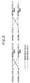
- the decoder makes a transition to internal state (0,0) when the input is 0 and a transition to internal state (0,1) when the input is 1; in the case of internal state (0,1) the decoder makes a transition to internal state (1,0) when the input is 0 and a transition to internal state (1,1) when the input is 1; in the case of the internal state (1,0) the decoder makes a transition to internal state (0,0) when the input is 0 and a transition to internal state (0,1) when the input is 1; and in the case of the internal state (1,1) the decoder makes a transition to internal state (1,0) when the input is 0 and a transition to internal state (1,1) when the input is 1.
- Fig.3 is a trellis diagram showing the above internal state transitions.
- the branches represented by solid line indicate transitions when the input is '0' and the branches represented by dashed line indicate transitions when the input is 1'.
- the numerals attached to each branch are the code symbols (G1, G2) output when the transition of the branch occurs.
- G1, G2 the code symbols
- the selection of the maximum likelihood path is made based on the probability information of each of the merging paths.
- a hard-decision Viterbi algorithm the Hamming distances between each path bit sequence and the received bit sequence are summed to produce the probability of the path.
- a soft-decision Viterbi algorithm the squares of the Euclidean distances between each path bit sequence and the received bit sequence are summed to produce the probability of the path.
- path metric the value presenting the probability of a path
- branch metric the value presenting the probability for each unit period of reception
- This path metric can be translated as a sum of the probabilities of transitions to a certain internal state.
- the branch metric can be translated as a sum of the probabilities of individual bits at a transition from one baibu state to the next internal state.
- the Euclidean distance between two strings of data, i.e., received data (r 1 , r 2 ) and data (s 1 , s 2 ) generated by a transmission meter is given as expression as follows: ( s 1 - r 1 ) 2 +( s 2 - r 2 ) 2
- received data (r 1 , r 2 ) is fixed and hence r 1 and r 2 are constant regardless of the values (s 1 , s 2 ), these can be omitted from the expression.
- transmitted data (s 1 , s 2 ) for elements s 1 and s 2 , assuming s 1 or s 2 to be '-1' when the data is '0' and assuming s 1 or s 2 to be '1' when the data is '1', s 1 2 and s 2 2 are constant regardless of the values (s 1 , s 2 ), so that these can be omitted from the expression. Further, when the remaining part is divided by 2, the expression is reduced to - s 1 ⁇ r 1 - s 2 ⁇ r 2 .
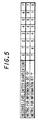
- the metrics shown in Fig.5 can be obtained from the above method.
- the soft-decision process performs decisions based on multi-levels signals.
- the branch metric results in '0' and if the received level is '7'
- the branch metric results in '7'.
- the branch metric results in '0'. It should be noted that the smaller this branch metric value, the more probable the branch is.
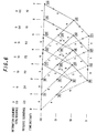
- Fig. 6 is a trellis diagram showing a soft-decision metric processing example.
- this soft-decision metric process suppose that an information sequence is given as '0110000', the code sequence is given as '00', '11', '10', '10', '11', '00' and '00', and the received sequence is given as '2', '4', '3', '6', '7', '2', '7', '5', '5', '7', '1', '0', '1' and '2'.
- the branch metrics for all the paths can be obtained in the same way.
- the numeral along each line segment denotes the branch metric and the numeral in hatching located at each internal-state and time-instant point denotes the path metric.
- the two paths merging into the internal state '00' at time instant '7' are one from the internal state '00' at time instant '6' and the other from the internal state '10' at time instant '6'.
- the path metric at time instant '6'/internal state '00' is '21' and the branch metric from the internal state '00' at time instant '6' to the internal state '00' at time instant '7' is '3', so that the probability of the path results in '24'.
- the path metric at time instant '6'/internal state '10' is '32' and the branch metric from the internal state '10' at time instant '6' to the internal state '00' at time instant '7' is '11', so that the probability of the path results in '43'. Therefore, '24' is assumed as the path metric at time instant '7'/internal state '00', that is, the path from the internal state '00' at time instant '6' to the internal state '00' at time instant '7' is selected.
- 'x' denotes the discarded path at the merging point.
- the decoded result can be obtained.
- the underlined numerals of the received sequence denotes error bits in transmission.
- the original information sequence can be obtained even when three bits of errors have occurred.
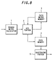
- Fig.8 shows a typical configuration of a Viterbi decoder for decoding convolutional codes based on the Viterbi algorithm, which is comprised of a branch metric calculator 1 for calculating the branch metric between the received sequence and each branch; an ACS portion 2 for selecting the survivor path and calculating the path metric of the survivor path; a path metric memory 3 for storing the path metric value at each internal state; apath memory 4 for storing the estimated output of a selected path; and a backtracing processor 5 for detecting the address of the most probable path metric and performing control of the path memory.
- a branch metric calculator 1 for calculating the branch metric between the received sequence and each branch
- an ACS portion 2 for selecting the survivor path and calculating the path metric of the survivor path
- a path metric memory 3 for storing the path metric value at each internal state
- apath memory 4 for storing the estimated output of a selected path
- a backtracing processor 5 for
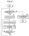
- the Viterbi decoder thus configured operates, as shown in the flowchart in Fig.9, in such a manner that it reads the received data and calculates branch metrics and updates the path metric into the path memory (Steps S2 to S5) until one entire frame is completed and when the frame has been completed (Step S1) then it outputs the decoded result by backtracing (Step S6).
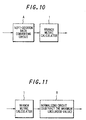
- a technique for such Viterbi decoders, various techniques have been proposed in order to improve calculation efficiency. As shown in Fig.10, a technique (see Japanese Patent Application Laid-Open Sho 63 No.122323) is disclosed in which a soft-decision data converting circuit A is provided so as to convert the input data in accordance with the circumstances so that it is used for calculations of branch metrics to thereby assign weights to the input bits.
- a normalizing circuit (maximum likelihood value subtraction) B is provided to search for the maximum likelihood value from all the branch metrics and subtract the value from each branch metric so as to narrow the data range to thereby determine the maximum likelihood value in branch metric.
- the data in a case of a Viterbi decoding process with a constraint length of 9 and a coding rate of 1/3, for example, when the bit accuracy of input data is set at three bits, the data can be correctly processed by an ACS portion having six or more internal operational bits if the process is combined with appropriate normalization.
- the input bit accuracy is set at four bits, not less than 7 or 8 internal operational bits are needed in the ACS portion even in combination with an appropriate normalization process.
- the internal operational bit length increases from six bits to 8 bits, the circuit scale also needs to be enlarged proportionally, to as large as a little over 1.3 times.
- the present invention is configured as follows.
- the first aspect of the present invention is a Viterbi decoder comprising: a branch metric calculating portion for calculating a branch metric value based on a received sequence; a bit range converting portion for converting a bit range of the branch metric value calculated by the branch metric calculating portion; a path metric calculating portion for calculating a path metric value based on the branch metric values whose bit range has been converted by the bit range converting portion; and a decoding portion for decoding received codes based on the path metric value calculated by the path metric calculating portion.
- the second aspect of the present invention is, in addition to the Viterbi decoder defined in the first aspect, is characterized in that the bit range converting portion converts the bit range by truncating a least significant bit of the branch metric value calculated by the branch metric calculating portion.
- the third aspect of the present invention is a method of Viterbi decoding comprising the steps of: calculating a branch metric value based on a received sequence; calculating a path metric value based on the branch metric values; and decoding received codes based on the path metric value, the method being characterized in that a bit range of the branch metric value is converted and the path metric value is calculated based on the branch metric values whose bit range has been converted.
- the branch metric calculating portion calculates branch metric values based on the received sequence, then the bit range converting portion converts the bit range of the calculated branch metric values into that operable by the path metric calculating portion.
- the path metric calculating portion calculates the path metric value based on the branch metric values whose bit range has been converted.
- the decoding portion decodes the received codes based on the calculated path metric value.
- the branch metric calculating portion calculates branch metric values based on a received sequence, then the bit range converting portion omit the least significant bit of the calculated branch metric values so as to converts the bit range of them into that operable by the path metric calculating portion.
- the path metric calculating portion calculates the path metric value based on the branch metric values whose bit range has been converted.
- the decoding portion decodes the received codes based on the calculated path metric value.
- branch metric values are calculated based on the received sequence, the bit range of the branch metric values is converted and the path metric value is calculated based on the branch metric values whose bit range has been converted. Then the received codes are decoded based on the path metric value.
- Fig.13 is a block diagram showing a configuration of a Viterbi decoder according to one embodiment of the present invention.
- This decoder is comprised of a branch metric calculator 1 for calculating the metric between the received sequence and each branch, a bit range converter 11 for converting the bit range of branch metric values calculated by branch metric calculator 1 so as to be suitable to the number of calculation bits to be used in an ACS portion 2, ACS portion 2 for selecting a survivor path and calculating the path metric of the survivor path, a path metric memory 3 for storing the path metric value of each internal state, a path memory 4 for storing the estimated output of a selected path; and a backtracing processor 5 for detecting the address of the most probable path metric and performing control of the path memory.
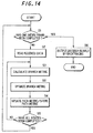
- the Viterbi decoder thus configured operates, as shown in the flowchart in Fig.14, in such a manner that it reads the received data and calculates the branch metrics, optimizes the branch metrics and updates the path metrics and stores them into the path memory (Steps S2 to S5, S11) until one frame is completed and when the frame has been completed (Step S1) then it outputs the decoded result by backtracing (Step S6).
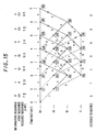
- Fig.15 is a trellis diagram showing a soft-decision metric processing example when the input bit precision is set at '4' in the Viterbi decoder thus configured as above.
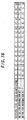
- this soft-decision metric process suppose that an information sequence is given as '0110000', the code sequence is given as '00', '11', '10', '10', '11', '00' and '00', and the received sequence is given as '7', '8', '5', '13', '10', '4', '12', '3', '3', '9', '5', '8', '6' and '5'.
- the branch metrics for all the paths can be calculated in the same way. In the diagram, the numeral along each line segment denotes the branch metric and the numeral in hatching located at each internal-state and time-instant point denotes its path metric.
- the two paths merging into the internal state '00' at time instant '7' are one from the internal state '00' at time instant '6' and the other from the internal state '10' at time instant '6'.
- the path metric at time instant '6'/internal state '00' is '35' and the branch metric from the internal state '00' at time instant '6' to the internal state '00' at time instant '7' is '5', so that the probability of the path results in '40'.
- the path metric at time instant '6'/internal state '10' is '32' and the branch metric from the internal state '10' at time instant '6' to the internal state '00' at time instant '7' is '9', so that the probability of the path results in '41'. Therefore, '40' is assumed as the path metric at time instant '7'/internal state '00', that is, the path from the internal state '00' at time instant '6' to the internal state '00' at time instant '7' is selected.
- 'x' denotes the discarded path at the merging point.
- the decoded result can be obtained.
- the underlined numerals of the received sequence denotes error bits in transmission.
- the original information sequence can be obtained even when four bits of errors have occurred.
- the received sequence is obtained as '3', '4', '2', '6', '5', '2', '6', '1', '1', '4', '2', '4', '3' and '2', as shown in Fig.17.
- Metric calculation based on this received sequence results as follows.
- the two paths merging into the internal state '00' at time instant '7' are one from the internal state '00' at time instant '6' and the other from the internal state '10' at time instant '6'.
- the path metric at time instant '6'/internal state '00' is '34' and the branch metric from the internal state '00' at time instant '6' to the internal state '00' at time instant '7' is '5', so that the probability of the path results in '39'.
- the path metric at time instant '6'/internal state '10' is '29' and the branch metric from the internal state '10' at time instant '6' to the internal state '00' at time instant '7' is '9', so that the probability of the path results in '38'. Therefore, '38' is assumed as the path metric at time instant '7'/internal state '00', that is, the path from the internal state '10' at time instant '6' to the internal state '00' at time instant '7' is selected.
- ' x' denotes the discarded path at the merging point.
- the decoded result can be obtained.
- a path selection fault occurs from the internal state '10' at time instant '6' to the internal state '00' at time instant '7', hence causes errors in the information sequence, thus making it impossible to obtain the original information sequence.
- Fig.18 is a BER characteristic chart showing the bit error ratio (BER) characteristic (with an input bit precision of '4') when the present embodiment is applied, in comparison with the bit error ratio (BER) characteristics (with an input bit precision of '3' and with an input bit precision of '4') of the conventional example.
- Fig.19 is a partially enlarged chart of the same chart. As understood from the charts, the embodiment shows some degradation compared to the conventional example wherein full calculation is performed with an input bit precision of '4', but presents some improvement in characteristics compared to the conventional example wherein full calculation is performed with an input bit precision of '3'.
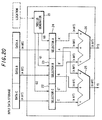
- Fig.20 is a constructional example of a branch metric calculator 1 in the Viterbi decoder configured as above.
- This calculator is comprised of a trellis generator 21, selectors 22, 23 and 24 and 6-bit adders 25 and 26.
- Trellis generator 21 is adapted to determine from which information bit, '0' or '1', a metric should be determined.
- a metric should be determined.
- selectors 22, 23 and 24 use respective metrics corresponding to information bit '0' for the received levels of data A, B and C.
- selectors 22 use respective metrics corresponding to information bit '0' for the received levels of data A, B and C.
- Each output from these selectors 22, 23 and 24 is supplied to adders 25 and 26, where these are summed to output branch metric values Y1 and Y2.
- the outputs from selectors 22, 23 and 24 range from 0 to 7. Therefore, the range of branch metrics is from 0 to 21 (10101b in binary), and the bit precision needs five bits.
- the outputs from selectors 22, 23 and 24 range from 0 to 15, so that the range of branch metrics is from 0 to 45 (101101b in binary) and the bit precision needs six bits.
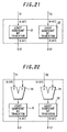
- Fig.21 is a constructional example of a bit range converter 11 in the Viterbi decoder configured as above.
- This converter is comprised of a least significant bit truncating portions 31 and 32.
- These least significant bit truncating portions 31 and 32 are adapted to drop the least significant bit of branch metric values Y1 and Y2 output from branch metric calculator 1, so that the values with their least significant bit truncated are output as branch metric values Y1' and Y2' having a bit length which is operable in ACS portion 2. More specifically, for example, when the input bit precision is set at four bits, the branch metric length is set at six bits taking into account the maximum value of the branch metric. Therefore this bit length is truncated into 5 bits as the number of bits which can be operated in ACS portion 2.
- branch metric calculator 1 it is possible to round the branch metric values Y1 and Y2 output from branch metric calculator 1 by adding '1' to each of them through 6-bit adders 33 and 34 and dropping the least significant bit through the least significant bit truncating portions 31 and 32.
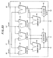
- Fig.23 is a constructional example of an ACS portion 2 in the Viterbi decoder configured as above.
- This ACS portion is comprised of 6-bit adders 41 to 44, comparators 45 and 46, selectors 47 and 48.
- adder 41 sums data K1 from path metric memory 3 and data Y1' from bit range converter 11 to output pt00
- adder 42 sums data K1 from path metric memory 3 and data Y2' from bit range converter 11 to output pt01
- adder 43 sums data K2 from path metric memory 3 and data Y2' from bit range converter 11 to output pt10
- adder 42 sums data K2 from path metric memory 3 and data Y1' from bit range converter 11 to output pt11.
- Comparator 45 compares pt00 and pt10 and outputs the result as the path data value to R1.
- Selector 47 in accordance with the result from comparator 45, selects pt00 if pt00 ⁇ pt10 or selects pt10 if pt00 > pt10 to output a new path metric S1.
- Comparator 46 compares pt01 and pt11 and outputs the result as the path data value to R2.
- Selector 48 in accordance with the result from comparator 46, selects pt01 if pt01 ⁇ pt11 or selects pt11 if pt01 > pt11 to output a new path metric S2.
- these new path metrics S1 and S2 are stored into path metric memory 3.
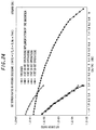
- Fig.24 shows the graphs for an uncoded case, a case with an input bit precision of 3 bits and operational bit length of 6 bits, a case where the present embodiment is employed with an input bit precision of 4 bits and operational bit length of 6 bits, a case where the present embodiment is not employed with an input bit precision of 4 bits and operational bit length of 6 bits and a case where the present embodiment is not employed with an input bit precision of 4 bits and operational bit length of 8 bits.
- Fig.25 shows its partially enlarged chart.
- the BER characteristic when the present embodiment is employed with an input bit precision of 4 bits or where the branch metric values are converted from 6 bits to 5 bits and internal operations are processed in 6 bits is more or less inferior to that when the input bit number is set at 4 bits and a large enough number of operational bits are taken or when the branch metric values are directly used with internal operations processed in 8 bits.
- the characteristic can be improved compared to the case where the input bit precision is set at 3 bits and a large enough number of operational bits are taken or where the circuit scale for internal operations is equivalent to the configuration of the embodiment.
- the invention is suitable for a Viterbi decoder which can improve error correction characteristics while suppressing enlargement in system scale.
Landscapes
- Physics & Mathematics (AREA)
- Probability & Statistics with Applications (AREA)
- Engineering & Computer Science (AREA)
- Theoretical Computer Science (AREA)
- Error Detection And Correction (AREA)
Abstract
It is an object to provide a Viterbi decoder whereby
the error correction characteristic is improved whilst
enlargement in system scale is suppressed.
For this purpose, a bit range converter(11) for
converting the bit range of the branch metric values calculated
by a branch metric calculator(1) to meet the number of
calculation bits used in an ACS portion(2) is provided between
branch metric calculator(1) and ACS portion(2) while the
decoder reads the received data and calculates the branch
metrics, optimizes the branch metrics and change the path
metric and store it into the path memory until the frame is
completed and when one frame has been completed then it outputs
the decoded result by backtracing.
Description
The present invention relates to a Viterbi decoder which
performs error correction of received convolutional codes.
Conventionally, the Viterbi decoding technique for
performing maximum likelihood decoding of convolutional codes
has been known. In this Viterbi decoding technique, since
a sequence closest to the received code sequence is selected,
based on the Viterbi decoding algorithm, from the code
sequences which could be generated on the transmitting side
encoder, it is possible to decode the received codes even
when they involve errors. In this way, the Viterbi decoding
technique has a high correcting capability against random
errors arising over the communication path, and in particular,
this technique can provide a great coding gain when combined
with soft decision decoding. Therefore, Viterbi decoders
have been widely adopted to decode error correction codes
for mobile communications systems and others.
To begin with, this Viterbi algorithm will be described
briefly. Here, consider convolutional codes with a coding
rate of 1/2 and a constraint length K=3 which are given by
generator polynomials,
G1(D) = 1+D2
G2(D) = 1+D+D2
where 'D' indicates the data delay and '+' indicates addition
of one bit only.
Fig.1 is a block diagram showing a configuration of a
Viterbi decoder for generating the above convolutional codes.
As shown in this figure, this Viterbi decoder is comprised
of shift registers, namely registers 101A and 101B, adders
102A, 102B and 102C for performing modulo-two addition. Here,
this decoder has four internal states, each given by (b1,
b2), explicitly, internal state (0,0), internal state (0,1),
internal state (1,0) and internal state (1,1), and each
internal state can make a transition to two internal states
when an input is given.
Specifically, as shown in Fig.2, in the case of internal
state (0,0) the decoder makes a transition to internal state
(0,0) when the input is 0 and a transition to internal state
(0,1) when the input is 1; in the case of internal state (0,1)
the decoder makes a transition to internal state (1,0) when
the input is 0 and a transition to internal state (1,1) when
the input is 1; in the case of the internal state (1,0) the
decoder makes a transition to internal state (0,0) when the
input is 0 and a transition to internal state (0,1) when the
input is 1; and in the case of the internal state (1,1) the
decoder makes a transition to internal state (1,0) when the
input is 0 and a transition to internal state (1,1) when the
input is 1.
Fig.3 is a trellis diagram showing the above internal
state transitions. In the diagram, the branches represented
by solid line indicate transitions when the input is '0' and
the branches represented by dashed line indicate transitions
when the input is 1'. The numerals attached to each branch
are the code symbols (G1, G2) output when the transition of
the branch occurs. As seen in this diagram, two paths always
merge at each state. In the Viterbi algorithm, the maximum
likelihood path is selected from the two paths at each internal
state, and when survivor paths up to a predetermined length
have been selected, the most probable one is detected from
the selected paths at different internal states to thereby
decode the received codes.
The selection of the maximum likelihood path is made
based on the probability information of each of the merging
paths. In a hard-decision Viterbi algorithm, the Hamming
distances between each path bit sequence and the received
bit sequence are summed to produce the probability of the
path. In a soft-decision Viterbi algorithm, the squares of
the Euclidean distances between each path bit sequence and
the received bit sequence are summed to produce the probability
of the path.
In the description hereinbelow, the value presenting
the probability of a path is called path metric, and the value
presenting the probability for each unit period of reception
is called branch metric. This path metric can be translated
as a sum of the probabilities of transitions to a certain
internal state. The branch metric can be translated as a sum
of the probabilities of individual bits at a transition from
one baibu state to the next internal state.
The Euclidean distance between two strings of data, i.e.,
received data (r1, r2) and data (s1, s2) generated by a
transmission meter is given as expression as follows:
(s 1 -r 1 )2 +(s 2 -r 2 )2
In Viterbi decoding, the square of the Euclidean distance
is expressed as:
(s 1 -r 1 )2 + (s 2 - r 2 )2 = s 1 2 -2×s 1 ×r 1 +r 1 2 +s 2 2 -2×s 2 ×r 2 +r 2 2
and data (s1, s2) which minimizes the above value of the
expression is determined.
Here, since received data (r1, r2) is fixed and hence
r1 and r2 are constant regardless of the values (s1, s2), these
can be omitted from the expression. Further, as to the
transmitted data (s1, s2), for elements s1 and s2, assuming
s1 or s2 to be '-1' when the data is '0' and assuming s1 or
s2 to be '1' when the data is '1', s1 2 and s2 2 are constant
regardless of the values (s1, s2), so that these can be omitted
from the expression. Further, when the remaining part is
divided by 2, the expression is reduced to -s 1×r 1-s 2×r 2.
From this expression, if s1=-1, -s 1×r 1 is r1. Hence if
r1=-1, the term -s 1 ×r 1 is reduced to -1, if r1=0, the term is
reduced to 0, and if r1= 1, the term is reduced to 1. If s1=
1, -s 1×r 1 is -r1. Hence if r1=-1, the term is reduced to 1,
if r1=0, the term is reduced to 0, and if r1= -1, the term
is reduced to 1.
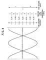
Accordingly, -s 1×r 1 results in a value linearly varying
from 0 to 2 in accordance with received data r1 (-1 to 1) if
s1=-1 whereas -s 1×r 1 results in a value linearly varying from
2 to 0 in accordance with received data r1 (-1 to 1) if s1=
1. When the resolution of received data r1 shown in Fig.4
is set at 3 bits, the metrics shown in Fig.5 can be obtained
from the above method.
Next, operations based on soft-decision processing will
be described. In contrast to the hard-decision process which
uses binary signals '0' and '1', the soft-decision process
performs decisions based on multi-levels signals. In
soft-decision using eight levels with three bits as shown
in Figs.4 and 5, assuming only one bit data, when the information
bit is '0', if the received level is '0', the branch metric
results in '0' and if the received level is '7', the branch
metric results in '7'. When the information bit is '0', if
the received level is '0', the branch metric results in '7'
and if the received level is '7', the branch metric results
in '0'. It should be noted that the smaller this branch metric
value, the more probable the branch is.
Fig. 6 is a trellis diagram showing a soft-decision metric
processing example. In this soft-decision metric process,
suppose that an information sequence is given as '0110000',
the code sequence is given as '00', '11', '10', '10', '11',
'00' and '00', and the received sequence is given as '2',
'4', '3', '6', '7', '2', '7', '5', '5', '7', '1', '0', '1'
and '2'. For the transition from the internal state '00' at
time instant '0' to the internal state '00' at time instant
'1', since the probability for the first bit '0' is '2' and
the probability for the second bit '0' is '4', the metric
results in '2+4' = '6'. The branch metrics for all the paths
can be obtained in the same way. In the diagram, the numeral
along each line segment denotes the branch metric and the
numeral in hatching located at each internal-state and
time-instant point denotes the path metric.
As a result of the calculation, the two paths merging
into the internal state '00' at time instant '7' are one from
the internal state '00' at time instant '6' and the other
from the internal state '10' at time instant '6'. As to the
path from the internal state '00' at time instant '6', the
path metric at time instant '6'/internal state '00' is '21'
and the branch metric from the internal state '00' at time
instant '6' to the internal state '00' at time instant '7'
is '3', so that the probability of the path results in '24'.
On the other hand, as to the path from the internal state
'10' at time instant '6', the path metric at time instant
'6'/internal state '10' is '32' and the branch metric from
the internal state '10' at time instant '6' to the internal
state '00' at time instant '7' is '11', so that the probability
of the path results in '43'. Therefore, '24' is assumed as
the path metric at time instant '7'/internal state '00', that
is, the path from the internal state '00' at time instant
'6' to the internal state '00' at time instant '7' is selected.
Here, in the diagram, 'x' denotes the discarded path at the
merging point.
As shown in Fig.7, by tracing the survivor path along
the arrows or in the reverse direction of the sequence of
the received data, the decoded result can be obtained. In
Fig.6, the underlined numerals of the received sequence
denotes error bits in transmission. As understood from the
decoded result, the original information sequence can be
obtained even when three bits of errors have occurred.
Fig.8 shows a typical configuration of a Viterbi decoder
for decoding convolutional codes based on the Viterbi
algorithm, which is comprised of a branch metric calculator
1 for calculating the branch metric between the received
sequence and each branch; an ACS portion 2 for selecting the
survivor path and calculating the path metric of the survivor
path; a path metric memory 3 for storing the path metric value
at each internal state; apath memory 4 for storing the estimated
output of a selected path; and a backtracing processor 5 for
detecting the address of the most probable path metric and
performing control of the path memory.
The Viterbi decoder thus configured operates, as shown
in the flowchart in Fig.9, in such a manner that it reads
the received data and calculates branch metrics and updates
the path metric into the path memory (Steps S2 to S5) until
one entire frame is completed and when the frame has been
completed (Step S1) then it outputs the decoded result by
backtracing (Step S6).
For such Viterbi decoders, various techniques have been
proposed in order to improve calculation efficiency. As shown
in Fig.10, a technique (see Japanese Patent Application
Laid-Open Sho 63 No.122323) is disclosed in which a
soft-decision data converting circuit A is provided so as
to convert the input data in accordance with the circumstances
so that it is used for calculations of branch metrics to thereby
assign weights to the input bits. Another technique (see
Japanese Patent Application Laid-Open Hei 7 No.245567) is
disclosed as shown in Fig.11, in which a normalizing circuit
(maximum likelihood value subtraction) B is provided to search
for the maximum likelihood value from all the branch metrics
and subtract the value from each branch metric so as to narrow
the data range to thereby determine the maximum likelihood
value in branch metric.
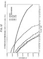
Use of soft-decision of the Viterbi algorithm improves
error collection characteristics as the bit precision of input
data is enhanced, as seen in the BER characteristic chart
in Fig. 12. However, enhancement of the bit precision of input
data increases the number of bits handled in the internal
processor, leading to the problem of system scale enlargement.
The same problem occurs with the method of assigning weights
on the input bits and with the normalizing method by determining
the maximum likelihood value in branch metric.
Illustratively, as shown in the BER characteristic chart
in Fig.12, in a case of a Viterbi decoding process with a
constraint length of 9 and a coding rate of 1/3, for example,
when the bit accuracy of input data is set at three bits,
the data can be correctly processed by an ACS portion having
six or more internal operational bits if the process is combined
with appropriate normalization. However, when the input bit
accuracy is set at four bits, not less than 7 or 8 internal
operational bits are needed in the ACS portion even in
combination with an appropriate normalization process. The
internal operational bit length increases from six bits to
8 bits, the circuit scale also needs to be enlarged
proportionally, to as large as a little over 1.3 times.
It is therefore an object of the present invention to
provide a Viterbi decoder which is able to improve error
correction characteristics while suppressing enlargement of
the system scale.
In order to solve the above problem, the present invention
is configured as follows.
The first aspect of the present invention is a Viterbi
decoder comprising: a branch metric calculating portion for
calculating a branch metric value based on a received sequence;
a bit range converting portion for converting a bit range
of the branch metric value calculated by the branch metric
calculating portion; a path metric calculating portion for
calculating a path metric value based on the branch metric
values whose bit range has been converted by the bit range
converting portion; and a decoding portion for decoding
received codes based on the path metric value calculated by
the path metric calculating portion.
The second aspect of the present invention is, in addition
to the Viterbi decoder defined in the first aspect, is
characterized in that the bit range converting portion
converts the bit range by truncating a least significant bit
of the branch metric value calculated by the branch metric
calculating portion.
The third aspect of the present invention is a method
of Viterbi decoding comprising the steps of: calculating a
branch metric value based on a received sequence; calculating
a path metric value based on the branch metric values; and
decoding received codes based on the path metric value,
the method being characterized in that a bit range of the
branch metric value is converted and the path metric value
is calculated based on the branch metric values whose bit
range has been converted.
According to the configurations of the present invention,
the following effects can be obtained.
According to the first configuration, the branch metric
calculating portion calculates branch metric values based
on the received sequence, then the bit range converting portion
converts the bit range of the calculated branch metric values
into that operable by the path metric calculating portion.
The path metric calculating portion calculates the path metric
value based on the branch metric values whose bit range has
been converted. The decoding portion decodes the received
codes based on the calculated path metric value. Thereby,
it is possible to improve the bit accuracy of input data without
increasing the number of internal operational bits handled
in the path metric calculating portion.
According to the second configuration, the branch metric
calculating portion calculates branch metric values based
on a received sequence, then the bit range converting portion
omit the least significant bit of the calculated branch metric
values so as to converts the bit range of them into that operable
by the path metric calculating portion. The path metric
calculating portion calculates the path metric value based
on the branch metric values whose bit range has been converted.
The decoding portion decodes the received codes based on the
calculated path metric value. Thereby, it is possible to
improve the bit accuracy of input data without increasing
the number of internal operational bits handled in the path
metric calculating portion.
According to the third configuration, branch metric
values are calculated based on the received sequence, the
bit range of the branch metric values is converted and the
path metric value is calculated based on the branch metric
values whose bit range has been converted. Then the received
codes are decoded based on the path metric value. Thereby,
it is possible to improve the bit accuracy of input data without
increasing the number of operational bits for calculation
of the path metric value.
The embodiment of the present invention will hereinbelow
be described in detail with reference to the drawings.
Fig.13 is a block diagram showing a configuration of
a Viterbi decoder according to one embodiment of the present
invention. This decoder is comprised of a branch metric
calculator 1 for calculating the metric between the received
sequence and each branch, a bit range converter 11 for
converting the bit range of branch metric values calculated
by branch metric calculator 1 so as to be suitable to the
number of calculation bits to be used in an ACS portion 2,
ACS portion 2 for selecting a survivor path and calculating
the path metric of the survivor path, a path metric memory
3 for storing the path metric value of each internal state,
a path memory 4 for storing the estimated output of a selected
path; and a backtracing processor 5 for detecting the address
of the most probable path metric and performing control of
the path memory.
The Viterbi decoder thus configured operates, as shown
in the flowchart in Fig.14, in such a manner that it reads
the received data and calculates the branch metrics, optimizes
the branch metrics and updates the path metrics and stores
them into the path memory (Steps S2 to S5, S11) until one
frame is completed and when the frame has been completed (Step
S1) then it outputs the decoded result by backtracing (Step
S6).
To begin with, a Viterbi decoder configured as above
with its constraint length set at 3 and coding rate set at
1/2 will be described. The generator polynomials as follows
are used:
G0 = 1 + D2
G1 = 1 + D + D2
Fig.15 is a trellis diagram showing a soft-decision
metric processing example when the input bit precision is
set at '4' in the Viterbi decoder thus configured as above.
In this soft-decision metric process, suppose that an
information sequence is given as '0110000', the code sequence
is given as '00', '11', '10', '10', '11', '00' and '00', and
the received sequence is given as '7', '8', '5', '13', '10',
'4', '12', '3', '3', '9', '5', '8', '6' and '5'. In this case,
for the transition from the internal state ' '00' at time instant
'0' to the internal state '00' at time instant '1', as shown
in the metric table in Fig.16, the probability for the first
bit '0' is '7' and the probability for the second bit '0'
is '8', so that the metric results in '7+8' = '15', or '1111',
and then the least significant bit is omitted by bit range
converter 11. Therefore, the metric results in '111' or '7'.
The branch metrics for all the paths can be calculated in
the same way. In the diagram, the numeral along each line
segment denotes the branch metric and the numeral in hatching
located at each internal-state and time-instant point denotes
its path metric.
As a result of the calculation, the two paths merging
into the internal state '00' at time instant '7' are one from
the internal state '00' at time instant '6' and the other
from the internal state '10' at time instant '6'. As to the
path from the internal state '00' at time instant '6', the
path metric at time instant '6'/internal state '00' is '35'
and the branch metric from the internal state '00' at time
instant '6' to the internal state '00' at time instant '7'
is '5', so that the probability of the path results in '40'.
On the other hand, as to the path from the internal state
'10' at time instant '6', the path metric at time instant
'6'/internal state '10' is '32' and the branch metric from
the internal state '10' at time instant '6' to the internal
state '00' at time instant '7' is '9', so that the probability
of the path results in '41'. Therefore, '40' is assumed as
the path metric at time instant '7'/internal state '00', that
is, the path from the internal state '00' at time instant
'6' to the internal state '00' at time instant '7' is selected.
Here, in the diagram, 'x' denotes the discarded path at the
merging point.
Then, by tracing the survivor path in the reverse
direction of the sequence of the received data, the decoded
result can be obtained. In Fig.15, the underlined numerals
of the received sequence denotes error bits in transmission.
As understood from this decoded result, the original
information sequence can be obtained even when four bits of
errors have occurred.
In contrast, when the same received signal is subjected
to the soft-decision metric process with an input bit accuracy
of '3' in the Viterbi decoder mentioned in reference to the
prior art, the received sequence is obtained as '3', '4',
'2', '6', '5', '2', '6', '1', '1', '4', '2', '4', '3' and
'2', as shown in Fig.17. Metric calculation based on this
received sequence results as follows. That is, the two paths
merging into the internal state '00' at time instant '7',
are one from the internal state '00' at time instant '6' and
the other from the internal state '10' at time instant '6'.
As to the path from the internal state '00' at time instant
'6', the path metric at time instant '6'/internal state '00'
is '34' and the branch metric from the internal state '00'
at time instant '6' to the internal state '00' at time instant
'7' is '5', so that the probability of the path results in
'39'. On the other hand, as to the path from the internal
state '10' at time instant '6', the path metric at time instant
'6'/internal state '10' is '29' and the branch metric from
the internal state '10' at time instant '6' to the internal
state '00' at time instant '7' is '9', so that the probability
of the path results in '38'. Therefore, '38' is assumed as
the path metric at time instant '7'/internal state '00', that
is, the path from the internal state '10' at time instant
'6' to the internal state '00' at time instant '7' is selected.
Here, in the diagram, ' x' denotes the discarded path at the
merging point.
Then, by tracing the survivor path in the reverse
direction of the sequence of the received data, the decoded
result can be obtained. However, as understood from this
decoded result, when four bits of errors have occurred, a
path selection fault occurs from the internal state '10' at
time instant '6' to the internal state '00' at time instant
'7', hence causes errors in the information sequence, thus
making it impossible to obtain the original information
sequence.
In this way, according to the present embodiment, it
is possible to improve error correction characteristics while
keeping the number of operational bits in ACS 3 from exceeding
'6'. Fig.18 is a BER characteristic chart showing the bit
error ratio (BER) characteristic (with an input bit precision
of '4') when the present embodiment is applied, in comparison
with the bit error ratio (BER) characteristics (with an input
bit precision of '3' and with an input bit precision of '4')
of the conventional example. Fig.19 is a partially enlarged
chart of the same chart. As understood from the charts, the
embodiment shows some degradation compared to the conventional
example wherein full calculation is performed with an input
bit precision of '4', but presents some improvement in
characteristics compared to the conventional example wherein
full calculation is performed with an input bit precision
of '3'.
Next, a Viterbi decoder configured as above, with its
constraint length set at 9 and coding rate set at 1/3 will
be described. The generator polynomials as follows are used:
G0 = 1 + D2 + D3 + D5 + D6 + D7 + D8
G1 = 1 + D + D3 + D4 + D7 + D8
G2 = 1 + D + D2 + D5 + D8 .
Fig.20 is a constructional example of a branch metric
calculator 1 in the Viterbi decoder configured as above. This
calculator is comprised of a trellis generator 21, selectors
22, 23 and 24 and 6-bit adders 25 and 26.
Trellis generator 21 is adapted to determine from which
information bit, '0' or '1', a metric should be determined.
In a calculating example at an internal state
'01111000b(=078h)', for input data '0',
G0 = 1+1+1 = 1
G1 = 1+1 = 0
G2 = 1 = 1.
For input data '1',
G0 = 1+1+1+1 = 0
G1 = 1+1+1 = 1
G2 = 1+1 = 0.
When G0, G1 and G2 are '0', selectors 22, 23 and 24 use
respective metrics corresponding to information bit '0' for
the received levels of data A, B and C. When G0, G1 and G2
are '1', the selectors use respective metrics corresponding
to information bit '0' for the received levels of data A,
B and C. Each output from these selectors 22, 23 and 24 is
supplied to adders 25 and 26, where these are summed to output
branch metric values Y1 and Y2.
When the input bit precision is set at three bits, the
outputs from selectors 22, 23 and 24 range from 0 to 7.
Therefore, the range of branch metrics is from 0 to 21 (10101b
in binary), and the bit precision needs five bits. When the
input bit precision is set at four bits, the outputs from
selectors 22, 23 and 24 range from 0 to 15, so that the range
of branch metrics is from 0 to 45 (101101b in binary) and
the bit precision needs six bits.
Fig.21 is a constructional example of a bit range
converter 11 in the Viterbi decoder configured as above. This
converter is comprised of a least significant bit truncating
portions 31 and 32. These least significant bit truncating
portions 31 and 32 are adapted to drop the least significant
bit of branch metric values Y1 and Y2 output from branch metric
calculator 1, so that the values with their least significant
bit truncated are output as branch metric values Y1' and Y2'
having a bit length which is operable in ACS portion 2. More
specifically, for example, when the input bit precision is
set at four bits, the branch metric length is set at six bits
taking into account the maximum value of the branch metric.
Therefore this bit length is truncated into 5 bits as the
number of bits which can be operated in ACS portion 2.
Here, as shown in Fig.22, it is possible to round the
branch metric values Y1 and Y2 output from branch metric
calculator 1 by adding '1' to each of them through 6-bit adders
33 and 34 and dropping the least significant bit through the
least significant bit truncating portions 31 and 32.
Fig.23 is a constructional example of an ACS portion
2 in the Viterbi decoder configured as above. This ACS portion
is comprised of 6-bit adders 41 to 44, comparators 45 and
46, selectors 47 and 48. Of these, adder 41 sums data K1 from
path metric memory 3 and data Y1' from bit range converter
11 to output pt00, adder 42 sums data K1 from path metric
memory 3 and data Y2' from bit range converter 11 to output
pt01, adder 43 sums data K2 from path metric memory 3 and
data Y2' from bit range converter 11 to output pt10, and adder
42 sums data K2 from path metric memory 3 and data Y1' from
bit range converter 11 to output pt11.
Comparator 45 compares pt00 and pt10 and outputs the
result as the path data value to R1. Selector 47, in accordance
with the result from comparator 45, selects pt00 if pt00 ≤
pt10 or selects pt10 if pt00 > pt10 to output a new path metric
S1. Comparator 46 compares pt01 and pt11 and outputs the
result as the path data value to R2. Selector 48, in accordance
with the result from comparator 46, selects pt01 if pt01 ≤
pt11 or selects pt11 if pt01 > pt11 to output a new path metric
S2. Here, these new path metrics S1 and S2 are stored into
path metric memory 3.
When the Viterbi algorithm process is implemented by
the above configurational example, the BER characteristic
shown in Fig.24 is obtained. Here, Fig.24 shows the graphs
for an uncoded case, a case with an input bit precision of
3 bits and operational bit length of 6 bits, a case where
the present embodiment is employed with an input bit precision
of 4 bits and operational bit length of 6 bits, a case where
the present embodiment is not employed with an input bit
precision of 4 bits and operational bit length of 6 bits and
a case where the present embodiment is not employed with an
input bit precision of 4 bits and operational bit length of
8 bits. Fig.25 shows its partially enlarged chart.
As understood from the drawings, the BER characteristic
when the present embodiment is employed with an input bit
precision of 4 bits or where the branch metric values are
converted from 6 bits to 5 bits and internal operations are
processed in 6 bits, is more or less inferior to that when
the input bit number is set at 4 bits and a large enough number
of operational bits are taken or when the branch metric values
are directly used with internal operations processed in 8
bits. However, the characteristic can be improved compared
to the case where the input bit precision is set at 3 bits
and a large enough number of operational bits are taken or
where the circuit scale for internal operations is equivalent
to the configuration of the embodiment.
As has been described heretofore, according to the
invention described in any one of the first through third
aspects, since it is possible to improve the bit accuracy
of the input data without increasing the number of operational
bits for calculating path metrics, it is possible to improve
error correction characteristic while suppressing
enlargement in system scale.
As has been described, the invention is suitable for
a Viterbi decoder which can improve error correction
characteristics while suppressing enlargement in system
scale.
Claims (3)
- A Viterbi decoder comprising:a branch metric calculating portion for calculating a branch metric value based on a received sequence;a bit range converting portion for converting a bit range of the branch metric value calculated by the branch metric calculating portion;a path metric calculating portion for calculating a path metric value based on the branch metric values whose bit range has been converted by the bit range converting portion; anda decoding portion for decoding received codes based on the path metric value calculated by the path metric calculating portion.
- The Viterbi decoder according to Claim 1, wherein the bit range converting portion converts the bit range by truncating a least significant bit of the branch metric value calculated by the branch metric calculating portion.
- A method of Viterbi decoding comprising the steps of:calculating a branch metric value based on a received sequence;calculating a path metric value based on the branch metric values; anddecoding received codes based on the path metric value, the method being characterized in that a bit range of the branch metric value is converted and the path metric value is calculated based on the branch metric values whose bit range has been converted.
Applications Claiming Priority (1)
| Application Number | Priority Date | Filing Date | Title |
|---|---|---|---|
| PCT/JP2000/001523 WO2001069796A1 (en) | 2000-03-14 | 2000-03-14 | Viterbi decoder |
Publications (2)
| Publication Number | Publication Date |
|---|---|
| EP1265367A1 true EP1265367A1 (en) | 2002-12-11 |
| EP1265367A4 EP1265367A4 (en) | 2005-06-15 |
Family
ID=11735790
Family Applications (1)
| Application Number | Title | Priority Date | Filing Date |
|---|---|---|---|
| EP00908047A Withdrawn EP1265367A4 (en) | 2000-03-14 | 2000-03-14 | Viterbi decoder |
Country Status (5)
| Country | Link |
|---|---|
| EP (1) | EP1265367A4 (en) |
| KR (1) | KR100490815B1 (en) |
| CN (1) | CN1211933C (en) |
| AU (2) | AU2000229439B2 (en) |
| WO (1) | WO2001069796A1 (en) |
Families Citing this family (3)
| Publication number | Priority date | Publication date | Assignee | Title |
|---|---|---|---|---|
| CN100429870C (en) * | 2005-08-08 | 2008-10-29 | 北京大学深圳研究生院 | VCP and method for deciding ACS data width |
| US20110167323A1 (en) * | 2010-01-07 | 2011-07-07 | Mediatek Inc. | Error-Correcting Apparatus and Method Thereof |
| CN102904667B (en) * | 2011-07-27 | 2015-05-20 | 开曼晨星半导体公司 | Method for decoding tail biting convolution codes of PBCH (physical broadcast channel) decoding in LTE (long term evolution) |
Family Cites Families (4)
| Publication number | Priority date | Publication date | Assignee | Title |
|---|---|---|---|---|
| JPH06338808A (en) * | 1993-05-28 | 1994-12-06 | Matsushita Electric Ind Co Ltd | Addition comparison selector |
| US5471500A (en) * | 1994-03-08 | 1995-11-28 | At&T Ipm Corp. | Soft symbol decoding |
| JPH0832633A (en) * | 1994-07-20 | 1996-02-02 | Toshiba Corp | Trellis decoder |
| KR100256270B1 (en) * | 1997-08-30 | 2000-05-15 | 김영환 | Apparatus and method for viterbi-decoding an encoding and encoding signal by rescaling a path metric |
-
2000
- 2000-03-14 WO PCT/JP2000/001523 patent/WO2001069796A1/en not_active Ceased
- 2000-03-14 AU AU2000229439A patent/AU2000229439B2/en not_active Ceased
- 2000-03-14 CN CNB008172153A patent/CN1211933C/en not_active Expired - Fee Related
- 2000-03-14 AU AU2943900A patent/AU2943900A/en active Pending
- 2000-03-14 EP EP00908047A patent/EP1265367A4/en not_active Withdrawn
- 2000-03-14 KR KR10-2002-7004693A patent/KR100490815B1/en not_active Expired - Fee Related
Also Published As
| Publication number | Publication date |
|---|---|
| AU2000229439B2 (en) | 2004-10-14 |
| CN1211933C (en) | 2005-07-20 |
| WO2001069796A1 (en) | 2001-09-20 |
| KR20020048963A (en) | 2002-06-24 |
| KR100490815B1 (en) | 2005-05-24 |
| EP1265367A4 (en) | 2005-06-15 |
| AU2943900A (en) | 2001-09-24 |
| CN1409899A (en) | 2003-04-09 |
Similar Documents
| Publication | Publication Date | Title |
|---|---|---|
| US5537444A (en) | Extended list output and soft symbol output viterbi algorithms | |
| US5406570A (en) | Method for a maximum likelihood decoding of a convolutional code with decision weighting, and corresponding decoder | |
| US6061823A (en) | Error correcting/decoding apparatus and error correcting/decoding method | |
| KR100580160B1 (en) | Modified Backtracking Two-Stage Viterbi Algorithm Decoder | |
| EP0671817A1 (en) | Soft symbol decoding for use in an MLSE-equaliser or convolutional decoder | |
| EP0529909B1 (en) | Error correction encoding/decoding method and apparatus therefor | |
| US7062000B1 (en) | Viterbi decoder | |
| US5450338A (en) | Add-compare-select device | |
| US7046747B2 (en) | Viterbi decoder and decoding method using rescaled branch metrics in add-compare-select operations | |
| EP1089441A2 (en) | Viterbi decoder and Viterbi decoding method | |
| AU2000229439B2 (en) | Viterbi decoder | |
| JP2917177B2 (en) | Error detection method, apparatus and identification method | |
| US7020223B2 (en) | Viterbi decoder and method using sequential two-way add-compare-select operations | |
| JP3823731B2 (en) | Error correction decoder | |
| US20040064781A1 (en) | Viterbi decoder and Viterbi decoding method | |
| JP3987153B2 (en) | Signal decoding for Viterbi decoder based on Manhattan or Hamming metric scheme | |
| EP0807336B1 (en) | Method for forming transition metrics and a receiver of a cellular radio system | |
| US6580769B1 (en) | Method and apparatus for backward recursion next state generation in recursive convolutional decoding | |
| KR101134806B1 (en) | Method for decoding code | |
| US6411663B1 (en) | Convolutional coder and viterbi decoder | |
| JP7835619B2 (en) | Error correction device, error correction method, and error correction program | |
| JPH05244017A (en) | Viterbi decoder | |
| EP0674397A2 (en) | Viterbi decoder comprising downsized circuits | |
| KR0180303B1 (en) | Standardization method and apparatus of viterbi decoder | |
| US20040153958A1 (en) | Path metric calculation circuit in viterbi decoders |
Legal Events
| Date | Code | Title | Description |
|---|---|---|---|
| PUAI | Public reference made under article 153(3) epc to a published international application that has entered the european phase |
Free format text: ORIGINAL CODE: 0009012 |
|
| 17P | Request for examination filed |
Effective date: 20020719 |
|
| AK | Designated contracting states |
Kind code of ref document: A1 Designated state(s): AT BE CH CY DE DK ES FI FR GB GR IE IT LI LU MC NL PT SE |
|
| RIN1 | Information on inventor provided before grant (corrected) |
Inventor name: KISHINO, MASAHIKO |
|
| RBV | Designated contracting states (corrected) |
Designated state(s): AT BE CH DE FR GB LI |
|
| A4 | Supplementary search report drawn up and despatched |
Effective date: 20050504 |
|
| STAA | Information on the status of an ep patent application or granted ep patent |
Free format text: STATUS: THE APPLICATION IS DEEMED TO BE WITHDRAWN |
|
| 18D | Application deemed to be withdrawn |
Effective date: 20101229 |