EP1265234A2 - Optical information recording medium - Google Patents
Optical information recording medium Download PDFInfo
- Publication number
- EP1265234A2 EP1265234A2 EP02012246A EP02012246A EP1265234A2 EP 1265234 A2 EP1265234 A2 EP 1265234A2 EP 02012246 A EP02012246 A EP 02012246A EP 02012246 A EP02012246 A EP 02012246A EP 1265234 A2 EP1265234 A2 EP 1265234A2
- Authority
- EP
- European Patent Office
- Prior art keywords
- dyes
- recording medium
- light
- optical information
- information recording
- Prior art date
- Legal status (The legal status is an assumption and is not a legal conclusion. Google has not performed a legal analysis and makes no representation as to the accuracy of the status listed.)
- Granted
Links
Images

Classifications
-
- G—PHYSICS
- G11—INFORMATION STORAGE
- G11B—INFORMATION STORAGE BASED ON RELATIVE MOVEMENT BETWEEN RECORD CARRIER AND TRANSDUCER
- G11B7/00—Recording or reproducing by optical means, e.g. recording using a thermal beam of optical radiation by modifying optical properties or the physical structure, reproducing using an optical beam at lower power by sensing optical properties; Record carriers therefor
- G11B7/24—Record carriers characterised by shape, structure or physical properties, or by the selection of the material
- G11B7/241—Record carriers characterised by shape, structure or physical properties, or by the selection of the material characterised by the selection of the material
- G11B7/252—Record carriers characterised by shape, structure or physical properties, or by the selection of the material characterised by the selection of the material of layers other than recording layers
- G11B7/254—Record carriers characterised by shape, structure or physical properties, or by the selection of the material characterised by the selection of the material of layers other than recording layers of protective topcoat layers
- G11B7/2542—Record carriers characterised by shape, structure or physical properties, or by the selection of the material characterised by the selection of the material of layers other than recording layers of protective topcoat layers consisting essentially of organic resins
-
- G—PHYSICS
- G11—INFORMATION STORAGE
- G11B—INFORMATION STORAGE BASED ON RELATIVE MOVEMENT BETWEEN RECORD CARRIER AND TRANSDUCER
- G11B7/00—Recording or reproducing by optical means, e.g. recording using a thermal beam of optical radiation by modifying optical properties or the physical structure, reproducing using an optical beam at lower power by sensing optical properties; Record carriers therefor
- G11B7/24—Record carriers characterised by shape, structure or physical properties, or by the selection of the material
- G11B7/241—Record carriers characterised by shape, structure or physical properties, or by the selection of the material characterised by the selection of the material
- G11B7/242—Record carriers characterised by shape, structure or physical properties, or by the selection of the material characterised by the selection of the material of recording layers
- G11B7/244—Record carriers characterised by shape, structure or physical properties, or by the selection of the material characterised by the selection of the material of recording layers comprising organic materials only
- G11B7/246—Record carriers characterised by shape, structure or physical properties, or by the selection of the material characterised by the selection of the material of recording layers comprising organic materials only containing dyes
-
- G—PHYSICS
- G11—INFORMATION STORAGE
- G11B—INFORMATION STORAGE BASED ON RELATIVE MOVEMENT BETWEEN RECORD CARRIER AND TRANSDUCER
- G11B7/00—Recording or reproducing by optical means, e.g. recording using a thermal beam of optical radiation by modifying optical properties or the physical structure, reproducing using an optical beam at lower power by sensing optical properties; Record carriers therefor
- G11B7/24—Record carriers characterised by shape, structure or physical properties, or by the selection of the material
- G11B7/26—Apparatus or processes specially adapted for the manufacture of record carriers
- G11B7/263—Preparing and using a stamper, e.g. pressing or injection molding substrates
-
- G—PHYSICS
- G11—INFORMATION STORAGE
- G11B—INFORMATION STORAGE BASED ON RELATIVE MOVEMENT BETWEEN RECORD CARRIER AND TRANSDUCER
- G11B7/00—Recording or reproducing by optical means, e.g. recording using a thermal beam of optical radiation by modifying optical properties or the physical structure, reproducing using an optical beam at lower power by sensing optical properties; Record carriers therefor
- G11B7/24—Record carriers characterised by shape, structure or physical properties, or by the selection of the material
- G11B7/241—Record carriers characterised by shape, structure or physical properties, or by the selection of the material characterised by the selection of the material
- G11B7/252—Record carriers characterised by shape, structure or physical properties, or by the selection of the material characterised by the selection of the material of layers other than recording layers
- G11B7/257—Record carriers characterised by shape, structure or physical properties, or by the selection of the material characterised by the selection of the material of layers other than recording layers of layers having properties involved in recording or reproduction, e.g. optical interference layers or sensitising layers or dielectric layers, which are protecting the recording layers
- G11B2007/25705—Record carriers characterised by shape, structure or physical properties, or by the selection of the material characterised by the selection of the material of layers other than recording layers of layers having properties involved in recording or reproduction, e.g. optical interference layers or sensitising layers or dielectric layers, which are protecting the recording layers consisting essentially of inorganic materials
- G11B2007/25706—Record carriers characterised by shape, structure or physical properties, or by the selection of the material characterised by the selection of the material of layers other than recording layers of layers having properties involved in recording or reproduction, e.g. optical interference layers or sensitising layers or dielectric layers, which are protecting the recording layers consisting essentially of inorganic materials containing transition metal elements (Zn, Fe, Co, Ni, Pt)
-
- G—PHYSICS
- G11—INFORMATION STORAGE
- G11B—INFORMATION STORAGE BASED ON RELATIVE MOVEMENT BETWEEN RECORD CARRIER AND TRANSDUCER
- G11B7/00—Recording or reproducing by optical means, e.g. recording using a thermal beam of optical radiation by modifying optical properties or the physical structure, reproducing using an optical beam at lower power by sensing optical properties; Record carriers therefor
- G11B7/24—Record carriers characterised by shape, structure or physical properties, or by the selection of the material
- G11B7/241—Record carriers characterised by shape, structure or physical properties, or by the selection of the material characterised by the selection of the material
- G11B7/252—Record carriers characterised by shape, structure or physical properties, or by the selection of the material characterised by the selection of the material of layers other than recording layers
- G11B7/257—Record carriers characterised by shape, structure or physical properties, or by the selection of the material characterised by the selection of the material of layers other than recording layers of layers having properties involved in recording or reproduction, e.g. optical interference layers or sensitising layers or dielectric layers, which are protecting the recording layers
- G11B2007/25705—Record carriers characterised by shape, structure or physical properties, or by the selection of the material characterised by the selection of the material of layers other than recording layers of layers having properties involved in recording or reproduction, e.g. optical interference layers or sensitising layers or dielectric layers, which are protecting the recording layers consisting essentially of inorganic materials
- G11B2007/2571—Record carriers characterised by shape, structure or physical properties, or by the selection of the material characterised by the selection of the material of layers other than recording layers of layers having properties involved in recording or reproduction, e.g. optical interference layers or sensitising layers or dielectric layers, which are protecting the recording layers consisting essentially of inorganic materials containing group 14 elements except carbon (Si, Ge, Sn, Pb)
-
- G—PHYSICS
- G11—INFORMATION STORAGE
- G11B—INFORMATION STORAGE BASED ON RELATIVE MOVEMENT BETWEEN RECORD CARRIER AND TRANSDUCER
- G11B7/00—Recording or reproducing by optical means, e.g. recording using a thermal beam of optical radiation by modifying optical properties or the physical structure, reproducing using an optical beam at lower power by sensing optical properties; Record carriers therefor
- G11B7/24—Record carriers characterised by shape, structure or physical properties, or by the selection of the material
- G11B7/241—Record carriers characterised by shape, structure or physical properties, or by the selection of the material characterised by the selection of the material
- G11B7/252—Record carriers characterised by shape, structure or physical properties, or by the selection of the material characterised by the selection of the material of layers other than recording layers
- G11B7/257—Record carriers characterised by shape, structure or physical properties, or by the selection of the material characterised by the selection of the material of layers other than recording layers of layers having properties involved in recording or reproduction, e.g. optical interference layers or sensitising layers or dielectric layers, which are protecting the recording layers
- G11B2007/25705—Record carriers characterised by shape, structure or physical properties, or by the selection of the material characterised by the selection of the material of layers other than recording layers of layers having properties involved in recording or reproduction, e.g. optical interference layers or sensitising layers or dielectric layers, which are protecting the recording layers consisting essentially of inorganic materials
- G11B2007/25715—Record carriers characterised by shape, structure or physical properties, or by the selection of the material characterised by the selection of the material of layers other than recording layers of layers having properties involved in recording or reproduction, e.g. optical interference layers or sensitising layers or dielectric layers, which are protecting the recording layers consisting essentially of inorganic materials containing oxygen
-
- G—PHYSICS
- G11—INFORMATION STORAGE
- G11B—INFORMATION STORAGE BASED ON RELATIVE MOVEMENT BETWEEN RECORD CARRIER AND TRANSDUCER
- G11B7/00—Recording or reproducing by optical means, e.g. recording using a thermal beam of optical radiation by modifying optical properties or the physical structure, reproducing using an optical beam at lower power by sensing optical properties; Record carriers therefor
- G11B7/24—Record carriers characterised by shape, structure or physical properties, or by the selection of the material
- G11B7/241—Record carriers characterised by shape, structure or physical properties, or by the selection of the material characterised by the selection of the material
- G11B7/252—Record carriers characterised by shape, structure or physical properties, or by the selection of the material characterised by the selection of the material of layers other than recording layers
- G11B7/257—Record carriers characterised by shape, structure or physical properties, or by the selection of the material characterised by the selection of the material of layers other than recording layers of layers having properties involved in recording or reproduction, e.g. optical interference layers or sensitising layers or dielectric layers, which are protecting the recording layers
- G11B2007/25705—Record carriers characterised by shape, structure or physical properties, or by the selection of the material characterised by the selection of the material of layers other than recording layers of layers having properties involved in recording or reproduction, e.g. optical interference layers or sensitising layers or dielectric layers, which are protecting the recording layers consisting essentially of inorganic materials
- G11B2007/25716—Record carriers characterised by shape, structure or physical properties, or by the selection of the material characterised by the selection of the material of layers other than recording layers of layers having properties involved in recording or reproduction, e.g. optical interference layers or sensitising layers or dielectric layers, which are protecting the recording layers consisting essentially of inorganic materials containing sulfur
-
- G—PHYSICS
- G11—INFORMATION STORAGE
- G11B—INFORMATION STORAGE BASED ON RELATIVE MOVEMENT BETWEEN RECORD CARRIER AND TRANSDUCER
- G11B7/00—Recording or reproducing by optical means, e.g. recording using a thermal beam of optical radiation by modifying optical properties or the physical structure, reproducing using an optical beam at lower power by sensing optical properties; Record carriers therefor
- G11B7/24—Record carriers characterised by shape, structure or physical properties, or by the selection of the material
- G11B7/241—Record carriers characterised by shape, structure or physical properties, or by the selection of the material characterised by the selection of the material
- G11B7/242—Record carriers characterised by shape, structure or physical properties, or by the selection of the material characterised by the selection of the material of recording layers
- G11B7/244—Record carriers characterised by shape, structure or physical properties, or by the selection of the material characterised by the selection of the material of recording layers comprising organic materials only
- G11B7/245—Record carriers characterised by shape, structure or physical properties, or by the selection of the material characterised by the selection of the material of recording layers comprising organic materials only containing a polymeric component
-
- G—PHYSICS
- G11—INFORMATION STORAGE
- G11B—INFORMATION STORAGE BASED ON RELATIVE MOVEMENT BETWEEN RECORD CARRIER AND TRANSDUCER
- G11B7/00—Recording or reproducing by optical means, e.g. recording using a thermal beam of optical radiation by modifying optical properties or the physical structure, reproducing using an optical beam at lower power by sensing optical properties; Record carriers therefor
- G11B7/24—Record carriers characterised by shape, structure or physical properties, or by the selection of the material
- G11B7/241—Record carriers characterised by shape, structure or physical properties, or by the selection of the material characterised by the selection of the material
- G11B7/242—Record carriers characterised by shape, structure or physical properties, or by the selection of the material characterised by the selection of the material of recording layers
- G11B7/244—Record carriers characterised by shape, structure or physical properties, or by the selection of the material characterised by the selection of the material of recording layers comprising organic materials only
- G11B7/246—Record carriers characterised by shape, structure or physical properties, or by the selection of the material characterised by the selection of the material of recording layers comprising organic materials only containing dyes
- G11B7/2467—Record carriers characterised by shape, structure or physical properties, or by the selection of the material characterised by the selection of the material of recording layers comprising organic materials only containing dyes azo-dyes
-
- G—PHYSICS
- G11—INFORMATION STORAGE
- G11B—INFORMATION STORAGE BASED ON RELATIVE MOVEMENT BETWEEN RECORD CARRIER AND TRANSDUCER
- G11B7/00—Recording or reproducing by optical means, e.g. recording using a thermal beam of optical radiation by modifying optical properties or the physical structure, reproducing using an optical beam at lower power by sensing optical properties; Record carriers therefor
- G11B7/24—Record carriers characterised by shape, structure or physical properties, or by the selection of the material
- G11B7/241—Record carriers characterised by shape, structure or physical properties, or by the selection of the material characterised by the selection of the material
- G11B7/242—Record carriers characterised by shape, structure or physical properties, or by the selection of the material characterised by the selection of the material of recording layers
- G11B7/244—Record carriers characterised by shape, structure or physical properties, or by the selection of the material characterised by the selection of the material of recording layers comprising organic materials only
- G11B7/246—Record carriers characterised by shape, structure or physical properties, or by the selection of the material characterised by the selection of the material of recording layers comprising organic materials only containing dyes
- G11B7/247—Record carriers characterised by shape, structure or physical properties, or by the selection of the material characterised by the selection of the material of recording layers comprising organic materials only containing dyes methine or polymethine dyes
- G11B7/2472—Record carriers characterised by shape, structure or physical properties, or by the selection of the material characterised by the selection of the material of recording layers comprising organic materials only containing dyes methine or polymethine dyes cyanine
-
- G—PHYSICS
- G11—INFORMATION STORAGE
- G11B—INFORMATION STORAGE BASED ON RELATIVE MOVEMENT BETWEEN RECORD CARRIER AND TRANSDUCER
- G11B7/00—Recording or reproducing by optical means, e.g. recording using a thermal beam of optical radiation by modifying optical properties or the physical structure, reproducing using an optical beam at lower power by sensing optical properties; Record carriers therefor
- G11B7/24—Record carriers characterised by shape, structure or physical properties, or by the selection of the material
- G11B7/241—Record carriers characterised by shape, structure or physical properties, or by the selection of the material characterised by the selection of the material
- G11B7/242—Record carriers characterised by shape, structure or physical properties, or by the selection of the material characterised by the selection of the material of recording layers
- G11B7/244—Record carriers characterised by shape, structure or physical properties, or by the selection of the material characterised by the selection of the material of recording layers comprising organic materials only
- G11B7/246—Record carriers characterised by shape, structure or physical properties, or by the selection of the material characterised by the selection of the material of recording layers comprising organic materials only containing dyes
- G11B7/247—Record carriers characterised by shape, structure or physical properties, or by the selection of the material characterised by the selection of the material of recording layers comprising organic materials only containing dyes methine or polymethine dyes
- G11B7/2475—Record carriers characterised by shape, structure or physical properties, or by the selection of the material characterised by the selection of the material of recording layers comprising organic materials only containing dyes methine or polymethine dyes merocyanine
-
- G—PHYSICS
- G11—INFORMATION STORAGE
- G11B—INFORMATION STORAGE BASED ON RELATIVE MOVEMENT BETWEEN RECORD CARRIER AND TRANSDUCER
- G11B7/00—Recording or reproducing by optical means, e.g. recording using a thermal beam of optical radiation by modifying optical properties or the physical structure, reproducing using an optical beam at lower power by sensing optical properties; Record carriers therefor
- G11B7/24—Record carriers characterised by shape, structure or physical properties, or by the selection of the material
- G11B7/241—Record carriers characterised by shape, structure or physical properties, or by the selection of the material characterised by the selection of the material
- G11B7/242—Record carriers characterised by shape, structure or physical properties, or by the selection of the material characterised by the selection of the material of recording layers
- G11B7/244—Record carriers characterised by shape, structure or physical properties, or by the selection of the material characterised by the selection of the material of recording layers comprising organic materials only
- G11B7/246—Record carriers characterised by shape, structure or physical properties, or by the selection of the material characterised by the selection of the material of recording layers comprising organic materials only containing dyes
- G11B7/247—Record carriers characterised by shape, structure or physical properties, or by the selection of the material characterised by the selection of the material of recording layers comprising organic materials only containing dyes methine or polymethine dyes
- G11B7/2478—Record carriers characterised by shape, structure or physical properties, or by the selection of the material characterised by the selection of the material of recording layers comprising organic materials only containing dyes methine or polymethine dyes oxonol
-
- G—PHYSICS
- G11—INFORMATION STORAGE
- G11B—INFORMATION STORAGE BASED ON RELATIVE MOVEMENT BETWEEN RECORD CARRIER AND TRANSDUCER
- G11B7/00—Recording or reproducing by optical means, e.g. recording using a thermal beam of optical radiation by modifying optical properties or the physical structure, reproducing using an optical beam at lower power by sensing optical properties; Record carriers therefor
- G11B7/24—Record carriers characterised by shape, structure or physical properties, or by the selection of the material
- G11B7/241—Record carriers characterised by shape, structure or physical properties, or by the selection of the material characterised by the selection of the material
- G11B7/242—Record carriers characterised by shape, structure or physical properties, or by the selection of the material characterised by the selection of the material of recording layers
- G11B7/244—Record carriers characterised by shape, structure or physical properties, or by the selection of the material characterised by the selection of the material of recording layers comprising organic materials only
- G11B7/246—Record carriers characterised by shape, structure or physical properties, or by the selection of the material characterised by the selection of the material of recording layers comprising organic materials only containing dyes
- G11B7/248—Record carriers characterised by shape, structure or physical properties, or by the selection of the material characterised by the selection of the material of recording layers comprising organic materials only containing dyes porphines; azaporphines, e.g. phthalocyanines
-
- G—PHYSICS
- G11—INFORMATION STORAGE
- G11B—INFORMATION STORAGE BASED ON RELATIVE MOVEMENT BETWEEN RECORD CARRIER AND TRANSDUCER
- G11B7/00—Recording or reproducing by optical means, e.g. recording using a thermal beam of optical radiation by modifying optical properties or the physical structure, reproducing using an optical beam at lower power by sensing optical properties; Record carriers therefor
- G11B7/24—Record carriers characterised by shape, structure or physical properties, or by the selection of the material
- G11B7/241—Record carriers characterised by shape, structure or physical properties, or by the selection of the material characterised by the selection of the material
- G11B7/242—Record carriers characterised by shape, structure or physical properties, or by the selection of the material characterised by the selection of the material of recording layers
- G11B7/244—Record carriers characterised by shape, structure or physical properties, or by the selection of the material characterised by the selection of the material of recording layers comprising organic materials only
- G11B7/249—Record carriers characterised by shape, structure or physical properties, or by the selection of the material characterised by the selection of the material of recording layers comprising organic materials only containing organometallic compounds
-
- G—PHYSICS
- G11—INFORMATION STORAGE
- G11B—INFORMATION STORAGE BASED ON RELATIVE MOVEMENT BETWEEN RECORD CARRIER AND TRANSDUCER
- G11B7/00—Recording or reproducing by optical means, e.g. recording using a thermal beam of optical radiation by modifying optical properties or the physical structure, reproducing using an optical beam at lower power by sensing optical properties; Record carriers therefor
- G11B7/24—Record carriers characterised by shape, structure or physical properties, or by the selection of the material
- G11B7/241—Record carriers characterised by shape, structure or physical properties, or by the selection of the material characterised by the selection of the material
- G11B7/252—Record carriers characterised by shape, structure or physical properties, or by the selection of the material characterised by the selection of the material of layers other than recording layers
- G11B7/253—Record carriers characterised by shape, structure or physical properties, or by the selection of the material characterised by the selection of the material of layers other than recording layers of substrates
- G11B7/2533—Record carriers characterised by shape, structure or physical properties, or by the selection of the material characterised by the selection of the material of layers other than recording layers of substrates comprising resins
-
- G—PHYSICS
- G11—INFORMATION STORAGE
- G11B—INFORMATION STORAGE BASED ON RELATIVE MOVEMENT BETWEEN RECORD CARRIER AND TRANSDUCER
- G11B7/00—Recording or reproducing by optical means, e.g. recording using a thermal beam of optical radiation by modifying optical properties or the physical structure, reproducing using an optical beam at lower power by sensing optical properties; Record carriers therefor
- G11B7/24—Record carriers characterised by shape, structure or physical properties, or by the selection of the material
- G11B7/241—Record carriers characterised by shape, structure or physical properties, or by the selection of the material characterised by the selection of the material
- G11B7/252—Record carriers characterised by shape, structure or physical properties, or by the selection of the material characterised by the selection of the material of layers other than recording layers
- G11B7/253—Record carriers characterised by shape, structure or physical properties, or by the selection of the material characterised by the selection of the material of layers other than recording layers of substrates
- G11B7/2533—Record carriers characterised by shape, structure or physical properties, or by the selection of the material characterised by the selection of the material of layers other than recording layers of substrates comprising resins
- G11B7/2534—Record carriers characterised by shape, structure or physical properties, or by the selection of the material characterised by the selection of the material of layers other than recording layers of substrates comprising resins polycarbonates [PC]
-
- G—PHYSICS
- G11—INFORMATION STORAGE
- G11B—INFORMATION STORAGE BASED ON RELATIVE MOVEMENT BETWEEN RECORD CARRIER AND TRANSDUCER
- G11B7/00—Recording or reproducing by optical means, e.g. recording using a thermal beam of optical radiation by modifying optical properties or the physical structure, reproducing using an optical beam at lower power by sensing optical properties; Record carriers therefor
- G11B7/24—Record carriers characterised by shape, structure or physical properties, or by the selection of the material
- G11B7/241—Record carriers characterised by shape, structure or physical properties, or by the selection of the material characterised by the selection of the material
- G11B7/252—Record carriers characterised by shape, structure or physical properties, or by the selection of the material characterised by the selection of the material of layers other than recording layers
- G11B7/256—Record carriers characterised by shape, structure or physical properties, or by the selection of the material characterised by the selection of the material of layers other than recording layers of layers improving adhesion between layers
-
- Y—GENERAL TAGGING OF NEW TECHNOLOGICAL DEVELOPMENTS; GENERAL TAGGING OF CROSS-SECTIONAL TECHNOLOGIES SPANNING OVER SEVERAL SECTIONS OF THE IPC; TECHNICAL SUBJECTS COVERED BY FORMER USPC CROSS-REFERENCE ART COLLECTIONS [XRACs] AND DIGESTS
- Y10—TECHNICAL SUBJECTS COVERED BY FORMER USPC
- Y10T—TECHNICAL SUBJECTS COVERED BY FORMER US CLASSIFICATION
- Y10T428/00—Stock material or miscellaneous articles
- Y10T428/21—Circular sheet or circular blank
Definitions
- the present invention relates to an optical information recording medium, and in particular to improvements in heat-mode writable optical information recording media.
- a CD-R is a widely known writable optical information recoding medium (optical disc) on which information can be written only once by irradiation with laser light.
- a CD-R typically has a recording layer containing an organic colorant, a light-reflective layer containing metals such as gold, and a protective layer composed of resins,laminated in this order on a transparent disc substrate.
- Information is recorded on the CD-R by irradiating it with near-IR laser light (generally having a wavelength of around 780 nm).
- the recording layer of the optical disc absorbs light which causes a temperature increase at an exposed portion, resulting in a physical or chemical change (for example, formation of pits) and, in turn, a change in the optical properties of that portion, whereby information data are recorded at that portion.
- the CD-R is, in general, irradiated with laser light having the same wavelength as that of the light used for information recording, and a difference in reflectance is detected between at the portions having (recorded area) and those not having (non-recorded area) the optical change produced in the recording layer.
- DVD-R writable digital versatile disc
- a DVD-R is so constructed that two discs each having an organic colorant-containing recording layer, a light-reflective layer and a protective layer are laminated in this order on a transparent disc substrate are laminated with the recording layers of the two discs facing inside, or is so constructed that one recording disc of the type described above is laminated with a protective disc substrate having the same form as that of the recording disc, also with the recording layer facing inside.
- the transparent disc substrate is processed so as to have a narrow guide groove (pre-groove) for laser light tracking, and a width of the groove, which is, for example, from 0.74 to 0.8 ⁇ m is less than half as wide as that in a CD-R.
- Information recording and reading are performed by irradiating the DVD-R with visible laser light (generally having a wavelength within a range of from 630 nm to 680 nm), and higher density recording is possible than on a CD-R.
- JP-A Japanese Patent Application Laid Open
- JP-A Japanese Patent Application Laid Open
- Nos. 4-74690, 7-304256, 7-304257, 8-127174, 11-53758, 11-334204, 11-334205, 11-334206, 11-334207, 2000-43423, 2000-108513, 2000-113504, 2000-149320, 2000-158818 and 2000-228028 disclose methods for recording and reading information by irradiating optical information recording media, having an organic colorant-containing recording layer, with laser light, having a wavelength no longer than 530 nm, from a recording layer side thereof toward the light-reflective layer side thereof.
- an optical disc having a recording layer that contains any of porphyrin compounds, azo dyes, metal azo dyes, quinophthalone dyes, trimethinecyanine dyes, dicyanovinylphenyl skeleton-having dyes, coumarin compounds or naphthalocyanine compounds is irradiated with blue (430 nm, 488 nm) or blue-green (515 nm) laser light for recording information thereon and reading information therefrom.
- optical information recoding media capable of recording and reading via laser light of different two wavelength ranges are proposed.
- JP-A Nos. 2000-141900, 2000-158816, 2000-185471, 2000-289342 and 2000-309165 propose optical information recording media capable of recording and reading with any laser light of a near-IR laser light range of around 780 nm or visible laser light range of around 650 nm, by mixing the colorants used in CD-Rs and those used in DVD-Rs.
- a transparent cover layer is generally formed on a surface opposite to the substrate of the optical discs mentioned above. Since the cover layer absorbs short-wave or long-wave light, the colorants, such as phthalocyanine dyes, contained in the recording layer of the optical discs are decomposed over time by light that passes through the cover layer, and the storage stability of the optical discs is often inferior.
- a tabular substrate having a thickness of, for example, 0.6 mm is adhered to a dummy substrate having a thickness of, for example, 0.6 mm, and necessary visible information and decoration for increasing commercial value are printed on the surface of the dummy substrate.
- This printing on the dummy substrate is carried out via various printing methods such as pad printing, screen printing or offset printing for full-color prints, and the same printing pattern is used for all recording discs produced on one production line.
- disc recording media are generally formed of a transparent polycarbonate resin. Therefore, if surfaces thereof do not have decoration or titles printed thereon, one can not be differentiated from another, and in addition, they leave an uninteresting impression and therefore Often have low commercial value.
- the printing pattern is varied for every recording disc when a conventional pad printing or screen printing method is used, different printing plates must be prepared for all of the intended printing patterns, and this is costly and time consuming. Therefore, it is impossible to readily change the contents of the printing, and for prints of many colors, increased cost and complexity of the printing process represent another problem.
- One object of the present invention is to provide an optical information recoding medium having stable recording and reading characteristics and having good storage stability, including light resistance and heat resistance, by preventing colorants in a recording layer therein from being decomposed.
- Another object of the invention is to make it possible to readily fabricate recording discs of different appearances that can be individually differentiated from each other and to thereby further increase the commercial value of the recording discs.
- the invention provides an optical information recording medium having, on a substrate, at least a light-reflective layer, a recording layer on which information can be recorded via laser light of wavelength no longer than 500 nm, and a cover layer containing at least one of UV absorbents that block out light of wavelength no longer than 400 nm and dyes that block out light of wavelength no shorter than 500 nm, formed in this order.
- the invention provides a disc recording medium having a recording layer on which information can be recorded and reading the recorded information can be reproduced via irradiation with light, wherein a substrate opposite to a disc surface that is irradiated with light contains a colorant material.
- the substrate opposite to the disc surface that is irradiated with light is colored. Printing of background color on the discs can therefore be omitted, and a printing step only requires printing necessary information thereon. Printing frequency can be reduced or printing can be completely omitted, thus simplifying the process of fabricating the recording discs.
- each optical disc recording medium may have a multi-color marble pattern, enhancing its appearance, and increasing its commercial value .
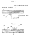
- Fig. 1 is a partial vertical cross section of a single-sided disc-type DVD of, a first embodiment of an optical information recording medium of the present invention.
- Fig. 2 is a vertical cross-sectional view showing a modification of the first embodiment of the optical information recording medium of the present invention.
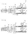
- Fig. 3A and Fig. 3B are cross-sectional views showing a multi-color injection molding device for molding two color resins in a second embodiment of the present invention.
- Fig. 4A and Fig. 4B are the appearances of substrates with an irregular pattern of entangled different color synthetic resin materials forming a marble pattern thereon.
- the optical information recording medium of the first aspect of the invention has a light-reflective layer, a recording layer and a cover layer formed on a substrate in this order.
- an adhesive layer is formed between the recording layer and the cover layer for firmly adhering the two layers to each other.
- the substrate and the constitutive layers are described below.
- any and every material used for the substrates of conventional optical information recording media can be used in any desired manner.
- the substrate materials include glass; polycarbonates; acrylic resins such as polymethyl methacrylate; vinyl chloride resins such as polyvinyl chloride, vinyl chloride copolymer; epoxy resins; amorphous polyolefins; polyesters; and metals such as aluminium. These materials may also be used in combination.
- amorphous polyolefins and polycarbonates are preferable because of good moisture resistance, good dimensional stability and inexpensiveness. Most preferable are polycarbonates.
- the thickness of the substrate is 1.1 ⁇ 0.3 mm.
- pre-groove concavo-convex groove
- the substrate having provided thereon a per-groove with a narrower track pitch in order to achieve a higher recording density compared with that obtained by CD-R or DVD-R.
- the track pitch of the pre-groove is indispensably from 200 to 400 ⁇ m, and preferably from 250 to 350 ⁇ m.
- the depth of the pre-groove is indispensably from 40 to 150 nm, and preferably from 50 to 120 nm.
- a subbing layer is preferably provided for improving the flatness and adhesiveness of the substrate.
- Examples of the materials for producing the subbing layer include polymers such as polymethyl methacrylate, acrylic acid/methacrylic acid copolymer, styrene/maleic anhydride copolymer, polyvinyl alcohol, N-methylolacrylamide, styrene/vinyltoluene copolymer, chlorosulfonated polyethylene, nitrocellulose, polyvinyl chloride, chlorinated polyolefin, polyester, polyimide, vinyl acetate/vinyl chloride copolymer, ethylene/vinyl acetate copolymer, polyethylene, polypropylene, polycarbonate; and surface modifiers such as silane-coupling agents.
- polymers such as polymethyl methacrylate, acrylic acid/methacrylic acid copolymer, styrene/maleic anhydride copolymer, polyvinyl alcohol, N-methylolacrylamide, styrene/vinyltoluene copolymer, chlor
- the subbing layer may be formed, for example, by dissolving or dispersing the above material in a suitable solvent to prepare a coating liquid, and then applying the coating liquid onto the surface of the substrate using any of coating methods such as spin coating, dip coating or extrusion coating.
- the thickness of the subbing layer is generally from 0.005 to 20 ⁇ m, and preferably from 0.01 ⁇ m to 10 ⁇ m.
- the light-reflective layer includes a light-reflective substance having high laser reflectance.
- the reflectance of the substance is at least 70%.
- the light-reflective substance of high reflectance include metals and semimetals such as Mg, Se, Y, Ti, Zr, Hf, V, Nb, Ta, Cr, Mo, W, Mn, Re, Fe, Co, Ni, Ru, Rh, Pd, Ir, Pt, Cu, Ag, Au, Zn, Cd, Al, Ga, In, Si, Ge, Te, Pb, Po, Sn, Bi; as well as stainless steel. These substances may be used either singly or in combination of two or more. Alloys thereof may also be sued.
- preferable are Cr, Ni, Pt, Cu, Ag, Au, Al and stainless steel, and more preferable are Au, Ag, Al and their alloys, and most preferable are Au, Ag and their alloys.
- the light-reflective layer may be formed on the substrate, for example, through vapor deposition, sputtering or ion plating of any of the above-mentioned light-reflective substances.
- the thickness of the light-reflective layer is generally from 10 nm to 300 nm, and preferably from 50 nm to 200 nm.
- the recording layer is formed on the light-reflective layer, and information can be recorded thereon by irradiation with laser light of a wavelength no longer than 600 nm.
- the recording layer contains a colorant.
- the colorant serving as a recording substance in the recoding layer may be any of phase-change metal compounds and organic compounds.
- organic compounds examples include cyanine dyes, oxonole dyes, metal complex dyes, azo dyes and phthalocyanine dyes.
- the dyes described in JP-A Nos. 4-74690, 8-127174, 11-53758, 11-334204, 11-334205, 11-334206, 11-334207, 2000-43423, 2000-108513 and 2000-158818 may be suitably used.
- the recording substance is not limited to such dyes, and other examples thereof include organic compounds such as triazole compounds, triazine compounds, cyanine compounds, merocyanine compounds, aminobutadiene compounds, phthalocyanine compounds, cinnamate compounds, viologen compounds, azo compounds, oxonole-benzoxazole compounds, and benzotriazole compounds.
- organic compounds such as triazole compounds, triazine compounds, cyanine compounds, merocyanine compounds, aminobutadiene compounds, phthalocyanine compounds, cinnamate compounds, viologen compounds, azo compounds, oxonole-benzoxazole compounds, and benzotriazole compounds.
- organic compounds such as triazole compounds, triazine compounds, cyanine compounds, merocyanine compounds, aminobutadiene compounds, phthalocyanine compounds, cinnamate compounds, viologen compounds, azo compounds, oxonole-benzoxazole compounds, and benzotriazo
- the recording layer may be formed, for example, by dissolving the recording substance such as the dye, together with a binder, in a suitable solvent to prepare a coating liquid, applying the coating liquid on the surface of the substrate to form a film thereon, and then allowing the coating liquid to dry.
- concentration of the recording substance present in the coating liquid is usually from 0.01 to 15 % by weight, preferably from 0.1 to 10 % by weight, more preferably from 0.5 to 5 % by weight, most preferably from 0.5 to 3 % by weight.
- Examples of the solvent used for the coating liquid include esters such as butyl acetate, ethyl lactate, cellosolve acetate; ketones such as methyl ethyl ketone, cyclohexanone, methyl isobutyl ketone; chlorinated hydrocarbons such as dichloromethane, 1,2-dichloroethane, chloroform; amides such as dimethylformamide; hydrocarbons such as methylcyclohexane; ethers such as tetrahydrofuran, ethyl ether, dioxane; alcohols such as ethanol, n-propanol, isopropanol, n-butanol diacetone alcohol; fluorine-based solvents such as 2,2,3,3-tetrafluoropropanol; and glycol ethers such as ethylene glycol monomethyl ether, ethylene glycol monoethyl ether, propylene glycol monomethyl ether.
- esters such
- the coating liquid may further include as needed various additives such as an antioxidant, a UV absorbent, a plasticizer and a lubricant.
- binder examples include natural organic polymers such as gelatin, cellulose derivatives, dextran, rosin, rubber; and synthetic organic polymers, for example, hydrocarbon resins such as polyethylene, polypropylene, polystyrene, polyisobutylene, vinylic resins such as polyvinyl chloride, polyvinylidene chloride, polyvinyl chloride/polyvinyl acetate copolymers, acrylic resins such as poly(methyl acrylate), poly(methyl methacrylate), polyvinyl alcohol, polyethylene chloride, epoxy resins, butyral resins, rubber derivatives, and precondensates of a thermosetting resin such as phenolformaldehyde resin.
- hydrocarbon resins such as polyethylene, polypropylene, polystyrene, polyisobutylene
- vinylic resins such as polyvinyl chloride, polyvinylidene chloride, polyvinyl chloride/polyvinyl acetate copolymers
- acrylic resins such
- the amount of the binder in the recording layer is generally from 0.01 times to 50 times (mass ratio), preferably from 0.1 times to 5 times (mass ratio) the amount of the recording substance used.
- the concentration of the recording substance present in the coating liquid is generally from 0.01 to 10 % by weight, preferably from 0.1 to 5 % by weight.
- the recording layer is formed by, for example, spraying, spin coating, dipping, roll coating, blade coating, doctor roll coating, or screen printing.
- the recording layer may be mono-layered or multi-layered.
- the thickness of the recording layer is generally from 20 nm to 500 nm, preferably from 30 nm to 300 nm, more preferably from 50 nm to 100 nm.
- the recording layer may optionally include a variety of fading inhibitors to improve the light resistance of the recoded layer.
- Singlet oxygen quenchers are usually employed as the fading inhibitor, and those described in patent and other publications may be used.
- the amount of the fading inhibitor such as a singlet oxygen quencher to be included in the recording layer is generally from 0.1 to 50 % by weight, preferably from 0.5 to 45 % by weight, more preferably from 3 to 40 % by weight, even more preferably from 5 to 25 % by weight of the colorant used.
- the adhesive layer is an optional layer formed for improving the adhesiveness between the recording layer and the cover layer mentioned below.
- the material for the adhesive layer is preferably a photocurable resin, more preferably that of low curing shrinkage for preventing the discs from warping.
- the photocurable resin of the type is, for example, a UV-curable resin (UV-curable adhesive) such as Dai-Nippon Ink's SD-640 and SD-347.
- the thickness of the adhesive layer is preferably from 1 to 1000 ⁇ m, more preferably from 5 to 500 ⁇ m, even more preferably from 10 to 100 ⁇ m.
- the cover layer is formed for preventing water from penetrating into the optical information recording medium.
- the cover layer of the optical information recording medium of the invention can block out light of a wavelength no longer than 400 nm and/or light of a wavelength no shorter than 500 nm, and it prevents the dyes in the recording layer from being photodecomposed. Having the cover layer, therefore, the storage stability of the optical information recording medium of the invention is good.
- the cover layer is not specifically defined so far as it is formed of a transparent material.
- it is formed of a polycarbonate, an acrylic resin such as polymethyl methacrylate, a vinyl chloride resin such as polyvinyl chloride or vinyl chloride copolymer, an epoxy resin, an amorphous polyolefin, a polyester, or cellulose triacetate. More preferably, it is formed of a polycarbonate or cellulose triacetate.
- the cover layer contains an UV absorbent for blocking out light of a wavelength no longer than 400 nm and/or a dye for blocking out light of a wavelength no shorter than 500 nm.
- transparent means that it transmits recording light and reading light (transmittance: at least 90 %) and is transparent to the light.
- the UV absorbent includes benzothiazoles, tetrazaindenes, thiouracils, benzotriazoles and their derivatives, and they block out light of a wavelength no longer than 400 nm.
- the dye includes phthalocyanine dyes, cyanine dyes, merocyanine dyes, azo dyes, immonium dyes, diimmonium dyes, pyrylium/thiopyrylium dyes, azulenium dyes, squalilium dyes, metal complex dyes with Ni or Cr, naphthoquinone dyes, anthraquinone dyes, indophenol dyes, indaniline dyes, triphenylmethane dyes, triallylmethane dyes, aluminium/diimmonium dyes and nitroso compounds, and they block out light of a wavelength no shorter than 500 nm.
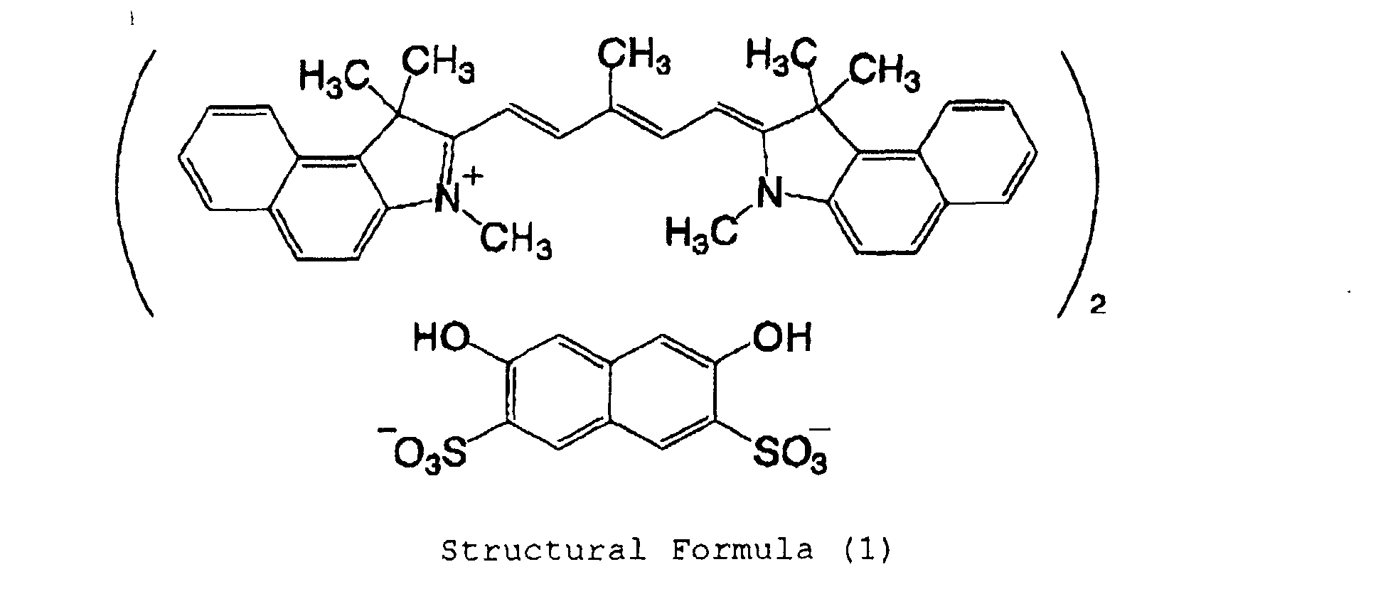
- Dyes of the following structural formula (1) or (2) also block out light of a wavelength no shorter than 500 nm, and are usable herein.
- the UV absorbent and the dye may be added to the cover layer by kneading it with the material for the layer, or dissolving or dispersing it in the material.
- the UV absorbent content of the cover layer is from 0.001 to 80 % by weight, more preferably from 0.1 to 50 % by weight.
- the absorbance of the cover layer will increase and the reflectance thereof will lower; but if smaller than 0.001 % by weight, the UV absorbent will be ineffective.
- the dye content of the cover layer is from 0.001 to 80 % by weight, more preferably from 0.1 to 50 % by weight.
- the absorbance of the cover layer will increase and the reflectance thereof will lower; but if smaller than 0.001 % by weight, the dye will be ineffective.
- the cover layer is formed as follows: A photocurable resin to form an adhesive layer is dissolved in a suitable solvent to prepare a coating solution, the coating solution is applied onto the recording layer at a predetermined temperature to form a coating film thereon, a film substrate with a UV absorbent and/or a dye added thereto in the manner mentioned above is laminated over the coating film, and this is irradiated with light over it to cure the coating film.
- the thickness of the cover layer is preferably from 0.01 to 0.2 mm, more preferably from 0.03 to 0.1 mm, even more preferably from 0.05 to 0.095 mm.
- the coating temperature ranges preferably from 23 to 50°C, more preferably from 24 to 40°C, even more preferably from 25 to 37°C.
- the coating film is preferably irradiated with a pulse light emitter (more preferably, a UV emitter).
- the pulse interval is preferably not larger than the level of msec, more preferably not larger than the level of ⁇ sec.
- the quantity of light irradiation in one pulse is not specifically defined, but is preferably at most 3 kW/cm 2 , more preferably at most 2 kW/cm 2 .
- the irradiation frequency is not also specifically defined, but is preferably at most 20 times, more preferably at most 10 times.
- a dielectric layer or a light-transmitting layer may be formed between the light-reflective layer and the recording layer, depending on the characteristics of the recording layer. For example, when a recording layer is provided, a light-transmitting layer may be provided for improving the adhesiveness to the recording layer, and when a phase-change recording layer is provided, a dielectric layer may be provided for heat radiation.
- the dielectric layer may be formed of a material of oxides, nitrides, carbides or sulfides of at least one of Zn, Si, Ti, Te, Sm, Mo and Ge, or their hybrids such as ZnS-SiO 2 .
- the light-transmitting layer may be formed of any and every material having a laser transmittance of at least 90 %.
- it may be formed of the same material as that for the dielectric layer mentioned above.
- the dielectric layer and the light-transmittance layer may be formed in any known method.
- the thickness of the dielectric layer is preferably from 1 to 100 nm, and the thickness of the light-transmitting layer is preferably from 2 to 50 ⁇ m.
- Fig. 1 shows a part of the vertical cross section of a single-sided disc-type DVD, a first embodiment of the disc recording medium of the invention.
- the disc recording medium 100 comprises a first disc substrate 21 having a thickness of 0.6 mm, which is formed by injection-molding a synthetic resin material, for example, a transparent polycarbonate resin in a mold that contains a stamper with information recorded thereon as a fine concavo-convex pattern and which has the concavo-convex pattern transferred from the stamper, and a second disc substrate 23 having a thickness of 0.6 mm, which is formed of a synthetic resin material (e.g., polycarbonate resin) containing a colorant material therein and which is adhered to the first disc substrate 21.
- a synthetic resin material e.g., polycarbonate resin
- the disc recording medium 100 is so designed that the data recorded on the recording layer 25 can be read out by irradiating the side of the transparent first substrate 21 with laser light 29 from a light pickup device 27 and detecting the laser light 29 reflected on the recording layer 25 by the light pickup device 27.
- the second substrate is formed of a colored synthetic resin material. Therefore, it is easy to make every disc recording medium 100 have its own appearance differing from the others by laminating any one of second substrates 23 having different colors onto the first substrate 21 of the same type, and every disc recording medium 100 thus produced can be readily differentiated from the others.
- the second substrate 23 is colored, background color printing on the discs in a printing step can be omitted, and the printing step can be finished only by printing the necessary information thereon.
- the printing frequency can be reduced or the printing operation can be completely omitted, and the process of fabricating the recording discs can be simplified.
- the disc recording medium of this embodiment illustrated herein is one example of a type having one recording layer.
- the invention is applicable to disc recording media of any other types in which the substrate opposite to that that is irradiated with light (or a specific layer portion of the substrate) is colored, for example, those of a type having two recording layers and those of a type for photomagnetic recording or reading.
- Fig. 2 is a vertical cross-sectional view of the modification of this embodiment, the disc recording medium 200.
- the disc recording medium 200 comprises a substrate 31 and a sheet 35 having a recording layer 33 attached to one surface of the substrate 31. This is irradiated with laser light 29 from a light pickup device 27 toward the sheet 35, the laser light 29 reflected on the recording layer 33 is detected by the light pickup device 27, and the data recorded on the recording layer 33 are thereby read out.
- the substrate 31 is formed of a disc of a synthetic resin material (for example, polycarbonate resin) that contains a colorant material. Therefore, sheets 35 of which the recording layer 33 has the same contents recorded thereon may be individually laminated onto any one of substrates 31 of different colors, and it is easy to make every disc recording medium 200 have its own appearance differing from the others.
- the substrate 31 is colored, background color printing on the discs in a printing step can be omitted like in the above, and therefore, the printing frequency can be reduced or the printing operation can be completely omitted, and the process of fabricating the recording discs can be simplified.
- the disc recording medium of this embodiment is fabricated by changing the monochromatic color of the second substrate 23 of the disc recording medium of the first embodiment (see Fig. 1) and that of the substrate 31 of the disc recording medium the modification of the first embodiment into a mixed color.
- the multi-color second substrate 23 or substrate 31 is combined with a recording layer attached thereto to construct the intended disc recording medium, like in the above.
- a multi-color injection molding method for example, known is a multi-color injection molding method. The multi-color injection molding method is employed as one example in this embodiment, and this is described below.
- Fig. 3A and Fig. 3B are cross-sectional views showing a multi-color injection molding device 40 for molding two color resin.
- the multi-color injection molding device 40 essentially comprises two injectors 41, 43; a mixer 45 in which the hot synthetic resin materials from the injectors 41, 43 are mixed; a fixed mold 47 and a movable mold 49, between which the cavity is filled with the mixed resin material from the mixer 45; and a driving mechanism 51 for moving the movable mold 49.
- the injectors 41, 43 have the same structure, each equipped with a hopper 53 into which the starting synthetic resin material 55 is put; an injection cylinder 57 in which the synthetic resin material 55 from the hopper 53 is heated; a screw 59 for delivering the synthetic resin material 55 to the tip of the injection cylinder 57; and a driving motor 61 for rotating the screw 59.
- the two synthetic resin materials are fed into the mixer 45 from the injectors 41, 43 via the respective inlet ducts, mixed in their flow channel, and then injected under high pressure into the cavity between the fixed mold 47 and the movable mold 49, as in Fig. 3A.
- the movable mold 49 is moved backward by the driving mechanism 51, and the molded substrate 60 (this corresponds to the second substrate 23 in Fig. 1, or the substrate 31 in Fig. 2) is taken out.
- Synthetic resin pellets 55A, 55B of different colors are put into the hopper 53 of the injector 41 and the hopper 53 of the injector 43, respectively; and these pellets 55A, 55B are simultaneously fed into the cavity of the molds 47, 49, through the injection cylinders 57 and via the mixer 45.
- the synthetic resin materials of different colors are mixed to form an irregular marble pattern as in Fig. 4A of Fig. 4B.
- the marble pattern changes every time when the resin pellets 55A, 55B of different colors are fed into the mold cavity, thereby to be an intrinsic pattern as in Fig. 4A or Fig. 4B. Therefore, substrates of different patterns can be formed in such a manner by merely repeating the injection molding operation as herein, not artificially changing the substrate design.
- a transparent synthetic resin material such as transparent polycarbonate resin is fed into the hopper 53 of the injector 41, while, on the other hand, a colored synthetic resin material is into the hopper 53 of the injector 43.
- the injector 41 serves as a main unit, and the injector 43 as a sub-unit.
- the resin supply ratio from the main unit is made larger than that from the sub-unit, and the two resin materials are injection-molded in that condition.
- the monochromatic substrate thus formed has such an intrinsic marble pattern.
- Synthetic resin pellets 55A, 55B of different colors are put into the hopper 53 of the injector 41 and the hopper 53 of the injector 43, respectively; and these pellets 55A, 55B are simultaneously fed into the cavity of the molds 47, 49, through the injection cylinders 57 and via the mixer 45 while the flow ratio of the pellets 55A, 55B is continuously varied.
- the synthetic resin materials of different colors are mixed while their blend ratio is varied, and substrates of different marble patterns are formed.
- the overall lightness of the substrates thus formed can be varied in any desired manner.
- the substrates formed in this method may have different patterns and different degree of lightness intrinsic to them.
- Synthetic resin materials of different colors are fed into the hoppers of the injectors at predetermined intervals in a predetermined order so that the colors of the synthetic resin materials to be fed into the injection cylinders from the hoppers are changed in order.
- a mixture of at least two synthetic resin materials of different colors is injected into the cavity of the molds.
- synthetic resin materials of different colors are mixed in a varying blend ratio in every injection molding operation, and are molded into substrates of different colors. Therefore, the color of the substrates molded in the method can be successively varied, for example, from red to orange, to yellow, to yellowish green, to green, to ..., and the method gives substrates of different colors that vary in every injection molding operation.
- substrates of two-color marble patterns can also be formed in the method.
- any known coloring methods are employable.
- a dry coloring method that comprises putting natural resin pellets and a powdery colorant into a drum mixer and rotating the drum mixer to thereby make the powdery colorant adhered to the resin pellets; and a master batch method that comprises blending a master batch of colorant pellets (this is prepared by mixing a starting resin with a high-concentration pigment of a desired color) with natural resin pellets in a desired ratio to thereby make the resin pellets colored with the colorant.
- the substrate of the disc recording material of the invention opposite to the side thereof that is irradiated with light is formed of a colorant-containing synthetic resin material. Therefore, the invention makes it possible to fabricate recording discs of different beautiful appearances that can be individually differentiated from the others, and makes it possible to increase the commercial value of the recording discs. In the process of producing the recording discs in the invention, the load in the printing step can be reduced and the production costs are therefore reduced.
- the dye coating solution was applied onto the reflective layer by spin coating at a varying speed of from 300 to 4000 rpm at 23°C and 50 % RH. This was stored at 23°C and 50 % RH for 1 hour to form a recording layer (thickness, 100 nm).
- a UV-curable adhesive (Dai-Nippon Ink and Chemical's SD-347) was applied onto the recording layer by spin coating at 100 to 300 rpm, and a cellulose triacetate film (FUJITAC by Fuji Photo Film, having a thickness of 0.08 mm) containing 10 % by weight of a UV absorbent, benzotriazole was put over it. This was rotated by a spin coater at a varying speed of from 300 to 400 rpm to fully spread the UV-curable adhesive, and irradiated with UV light from a UV lamp to cure the adhesive. This is a sample of the optical information recording medium of the invention.
- the cellulose triacetate film was prepared by adding benzotriazole to a cellulose triacetate solution, casting the solution on a band and drying it thereon to remove the solvent.
- Example 2 Ag was sputtered onto the same substrate as in Example 1 to form thereon a reflective layer having a thickness of 100 nm. Next, a dielectric layer of ZnS-SiO 2 having a thickness of 90 nm was formed thereon also by sputtering.
- FOM-561 ORASOL BLUE phthalocyanine dye by Wako Pure Chemical Industries
- the dye coating solution was applied onto the dielectric layer by spin coating at a varying speed of from 300 to 4000 rpm at 23°C and 50 % RH. This was stored at 23°C and 50 % RH for 1 hour to form a recording layer (thickness, 100 nm).
- a light-transmitting layer of SiO 2 having a thickness of 90 nm was formed on the recording layer by sputtering, and a UV-curable adhesive (Dai-Nippon Ink and Chemical's SD-661) was applied onto the light-transmitting layer by spin coating at 100 to 300 rpm.
- a UV-curable adhesive (Dai-Nippon Ink and Chemical's SD-661) was applied onto the light-transmitting layer by spin coating at 100 to 300 rpm.
- the dye was added to the polycarbonate film in the same manner as in Example 1.
- Example 2 Ag was sputtered onto the same substrate as in Example 1 to form thereon a reflective layer having a thickness of 100 nm.
- ORASOL BLUE GN phthalocyanine dye by Ciba Speciality Chemicals
- the dye coating solution was applied onto the reflective layer by spin coating at a varying speed of from 300 to 4000 rpm at 23°C and 50 % RH. This was stored at 23°C and 50 % RH for 1 hour to form a recording layer (thickness, 100 nm).
- a UV-curable adhesive (Dai-Nippon Ink and Chemical's SD-347) was applied onto the recording layer by spin coating at 100 to 300 rpm, and a cellulose triacetate film (FUJITAC by Fuji Photo Film, having a thickness of 0.08 mm) containing 20 % by weight of a dye of formula (1) mentioned above was put over it. This was rotated by a spin coater at a varying speed of from 300 to 4000 rpm to fully spread the adhesive, and irradiated with UV light from a UV lamp to cure the adhesive. This is a sample of the optical information recording medium of the invention.
- the dye of formula (1) used herein is a commercial product. This was added to the cellulose triacetate film in the same manner as in Example 1.
- Example 2 Ag was sputtered onto the same substrate as in Example 1 to form thereon a reflective layer having a thickness of 100 nm.
- 20 g of FOM-561 ORASOL BLUE phthalocyanine dye by Wako Pure Chemical Industries
- the dye coating solution was applied onto the reflective layer by spin coating at a varying speed of from 300 to 4000 rpm at 23°C and 50 % RH. This was stored at 23°C and 50 % RH for 1 hour to form a recording layer (thickness, 100 nm).
- a light-transmitting layer of SiO 2 having a thickness of 90 nm was formed on the recording layer by sputtering.
- a UV-curable adhesive (Dai-Nippon Ink and Chemical's SD-661) was applied onto the light-transmitting layer by spin coating at 100 to 300 rpm, and a polycarbonate film (thickness, 0.08 mm) containing 20 % by weight of a dye of formula (2) mentioned above was put over it. This was rotated by a spin coater at a varying speed of from 300 to 4000 rpm to fully spread the adhesive, and pulse-irradiated with UV light from a UV lamp to cure the adhesive. This is a sample of the optical information recording medium of the invention.
- the dye of formula (2) used herein is a commercial product. This was added to the polycarbonate film in the same manner as in Example 1.
- Example 2 Ag was sputtered onto the same substrate as in Example 1 to form thereon a reflective layer having a thickness of 100 nm.
- ORASOL BLUE GN phthalocyanine dye by Ciba Speciality Chemicals
- the dye coating solution was applied onto the reflective layer by spin coating at a varying speed of from 300 to 4000 rpm at 23°C and 50 % RH. This was stored at 23°C and 50 % RH for 1 hour to form a recording layer (thickness, 100 nm).
- a UV-curable adhesive (Dai-Nippon Ink and Chemical's SD-347) was applied onto the recording layer by spin coating at 100 to 300 rpm, and a cellulose triacetate film (FUJITAC by Fuji Photo Film, having a thickness of 0.08 mm) containing 20 % by weight of benzotriazole and 20 % by weight of a dye of formula (1) mentioned above was put over it.
- This is a sample of the optical information recording medium of the invention.
- Benzotriazole and the dye of formula (1) were added to a solution of cellulose triacetate, and the solution was formed into the film containing the two.
- Example 2 Ag was sputtered onto the same substrate as in Example 1 to form thereon a reflective layer having a thickness of 100 nm. Next, a dielectric layer of ZnS-SiO 2 having a thickness of 90 nm was formed thereon also by sputtering.
- FOM-561 ORASOL BLUE phthalocyanine dye by Wako Pure Chemical Industries
- the dye coating solution was applied onto the dielectric layer by spin coating at a varying speed of from 300 to 4000 rpm at 23°C and 50 % RH. This was stored at 23°C and 50 % RH for 1 hour to form a recording layer (thickness, 100 nm).
- a light-transmitting layer of SiO 2 having a thickness of 90 nm was formed on the recording layer by sputtering, and a UV-curable adhesive (Dai-Nippon Ink and Chemical's SD-661) was applied onto the light-transmitting layer by spin coating at 100 to 300 rpm.
- a UV-curable adhesive (Dai-Nippon Ink and Chemical's SD-661) was applied onto the light-transmitting layer by spin coating at 100 to 300 rpm.
- Benzotriazole and the dye of formula (2) were added to the polycarbonate film while the film was formed.
- Example 2 Ag was sputtered onto the same substrate as in Example 1 to form thereon a reflective layer having a thickness of 100 nm.
- ORASOL BLUE GN phthalocyanine dye by Ciba Speciality Chemicals
- 20 g of ORASOL BLUE GN phthalocyanine dye by Ciba Speciality Chemicals
- the dye coating solution was applied onto the reflective layer by spin coating at a varying speed of from 300 to 4000 rpm at 23°C and 50 % RH. This was stored at 23°C and 50 % RH for 1 hour to form a recording layer (thickness, 100 nm).
- a UV-curable adhesive (Dai-Nippon Ink and Chemical' s SD-347) was applied onto the recording layer by spin coating at 100 to 300 rpm, and a cellulose triacetate film (FUJITAC by Fuji Photo Film, having a thickness of 0.08 mm) was put over it. This was rotated by a spin coater at a varying speed of from 300 to 4000 rpm to fully spread the adhesive, and pulse-irradiated with UV light from a UV lamp to cure the adhesive. This is a comparative sample.
- optical information recording media obtained in Examples 1 to 6 and Comparative Example 1 were stored under the condition mentioned below.
- a 3T signal was recorded on these, using DDU-1000 (by Pulsetec) equipped with a 405 nm laser, and C/N was measured.
- the results are given in Table 1.
- each sample was irradiated with light (wavelength: 350 to 1000 nm) for 48 hours through its cover layer.
- the quantity of light from the tester was 335 W/m 2 , the temperature in the room was 60°C, and the humidity therein was 75 % RH.
- Example 1 55 db 52 db 53 db
- Example 2 45 db 41 db 42 db
- Example 3 55 db 50 db 52 db
- Example 4 45 db 40 db 41 db
- Example 5 55 db 54 db
- Example 6 45 db 44 db 44 db Comparative Example 1 55 db 15 db 20 db
- the samples of the optical information recording medium of the invention obtained in Examples 1 to 6 all had stable recording-reading characteristics even after faded and after stored in a thermo-box.
- the invention provides an optical information recoding medium having stable recording and reading characteristics and having good storage stability including light resistance and heat resistance by preventing the colorants in the recording layer therein from being decomposed.
- the invention makes it possible to fabricate a disc recording medium in which the substrate opposite to the side thereof that is irradiated with light contains a colorant material. According to the invention, therefore, it is easy to fabricate recording discs of different appearances that can be individually differentiated from the others.
- the invention makes it possible to reduce the production costs of the recording discs and to increase the commercial value thereof.
Landscapes
- Engineering & Computer Science (AREA)
- Manufacturing & Machinery (AREA)
- Optical Record Carriers And Manufacture Thereof (AREA)
- Thermal Transfer Or Thermal Recording In General (AREA)
Abstract
Description

| Before Stored | After Faded for 48 hours | After Stored in Thermo-box for 48 hours | |
| Example 1 | 55 db | 52 | 53 db |
| Example 2 | 45 | 41 db | 42 db |
| Example 3 | 55 db | 50 db | 52 db |
| Example 4 | 45 | 40 | 41 db |
| Example 5 | 55 db | 54 | 55 db |
| Example 6 | 45 db | 44 db | 44 db |
| Comparative Example 1 | 55 db | 15 db | 20 db |
Claims (20)
- An optical information recording medium comprising a substrate having successively disposed thereon at least a light-reflective layer, a recording layer on which information is recorded by laser light of a wavelength no longer than 500 nm, and a cover layer containing at least one of a UV absorbent that blocks out light of a wavelength no longer than 400 nm and a dye that blocks out light of a wavelength no shorter than 500 nm.
- The optical information recording medium of claim 1, wherein the substrate comprises at least one of amorphous polyolefins and polycarbonates.
- The optical information recording medium of claim 1, wherein the substrate comprises a polycarbonate.
- The optical information recording medium of claim 1, wherein the light-reflective layer comprises at least one selected from the group consisting of Cr, Ni, Pt, Cu, Ag, Au, Al and stainless steel.
- The optical information recording medium of claim 1, wherein the light-reflective layer comprise at least one selected from the group consisting of Ag, Au and Al.
- The optical information recording medium of claim 1, wherein the light-reflective layer comprises at least one of Ag and Au.
- The optical information recording medium of claim 1, wherein the recording layer comprises at least a dye selected from the group consisting of cyanine dyes, oxonole dyes, metal complex dyes, azo dyes and phthalocyanine dyes.
- The optical information recording medium of claim 1, wherein the recording layer comprises a compound selected from the group consisting of cyanine compounds, aminobutadiene compounds, benzotriazole compounds and phthalocyanine compounds.
- The optical information recording medium of claim 1, wherein the cover layer comprises a substance selected from the group consisting of polycarbonates, acrylic resins, vinyl chloride-based resins, epoxy resins, amorphous polyolefins, polyesters and cellulose triacetate.
- The optical information recording medium of claim 1, wherein the cover layer comprises a substance selected from the group consisting of polycarbonates, polymethyl methacrylate and polyvinyl chloride.
- The optical information recording medium of claim 1, wherein the UV absorbent is selected from the group consisting of benzothiazoles, tetrazaindenes, thiouracils, benzotriazoles and derivatives thereof.
- The optical information recording medium of claim 1, wherein the dye that blocks out light of a wavelength no shorter than 500 nm is selected from the group consisting of phthalocyanine dyes, cyanine dyes, merocyanine dyes, azo dyes, immonium dyes, diimmonium dyes, pyrylium/thiopyrylium dyes, azulenium dyes, squalilium dyes, Ni metal complex dyes, Cr metal complex dyes, naphthoquinone dyes, anthraquinone dyes, indophenol dyes, indaniline dyes, triphenylmethane dyes, triallylmethane dyes, aluminium diimmonium dyes and nitroso compounds.
- The optical information recording medium of claim 1, wherein the dye that blocks out light of a wavelength no shorter than 500 nm is represented by the following structural formula (1):

- The optical information recording medium of claim 1, wherein the dye that blocks out light of a wavelength no shorter than 500 nm is represented by the following structural formula (2):

- An optical information recording medium having a substrate that is irradiated with light to record information on a recording layer on the substrate and to read the recorded information, and another substrate disposed opposite to the substrate that is irradiated with light, wherein the another substrate contains a colorant material.
- An optical information recording disc having a substrate that is irradiated with light to record information on a recording layer on the substrate and to read the recorded information, and another substrate disposed opposite to the substrate that is irradiated with light, wherein the another substrate contains a colorant material.
- The optical information recording medium of claim 15, wherein the colorant material-containing substrate comprises a mixture of synthetic resin materials colored at least two different colors.
- The optical information recording medium of claim 15, wherein the substrate that is irradiated with light to record information on the recording layer and to read the recorded information has successively disposed thereon at least a light-reflective layer, the recording layer on which information is recorded by laser light of a wavelength no longer than 500 nm, and a cover layer containing at least one of a UV absorbent that blocks out light of a wavelength no longer than 400 nm and a dye that blocks out light of a wavelength no shorter than 500 nm.
- The optical information recording medium of claim 18, wherein the UV absorbent is selected from the group consisting of benzothiazoles, tetrazaindenes, thiouracils, benzotriazoles and derivatives thereof.
- The optical information recording medium of claim 18, wherein the dye that blocks out light of a wavelength no shorter than 500 nm is selected from the group consisting of phthalocyanine dyes, cyanine dyes, merocyanine dyes, azo dyes, immonium dyes, diimmonium dyes, pyrylium/thiopyrylium dyes, azulenium dyes, squalilium dyes, Ni metal complex dyes, Cr metal complex dyes, naphthoquinone dyes, anthraquinone dyes, indophenol dyes, indaniline dyes, triphenylmethane dyes, triallylmethane dyes, aluminium diimmonium dyes and nitroso compounds.
Applications Claiming Priority (2)
| Application Number | Priority Date | Filing Date | Title |
|---|---|---|---|
| JP2001168274 | 2001-06-04 | ||
| JP2001168274A JP2002367227A (en) | 2001-06-04 | 2001-06-04 | Optical information recording medium |
Publications (3)
| Publication Number | Publication Date |
|---|---|
| EP1265234A2 true EP1265234A2 (en) | 2002-12-11 |
| EP1265234A3 EP1265234A3 (en) | 2004-03-24 |
| EP1265234B1 EP1265234B1 (en) | 2006-05-10 |
Family
ID=19010523
Family Applications (1)
| Application Number | Title | Priority Date | Filing Date |
|---|---|---|---|
| EP02012246A Expired - Lifetime EP1265234B1 (en) | 2001-06-04 | 2002-06-03 | Optical information recording medium |
Country Status (4)
| Country | Link |
|---|---|
| US (1) | US6815030B2 (en) |
| EP (1) | EP1265234B1 (en) |
| JP (1) | JP2002367227A (en) |
| DE (1) | DE60211250T2 (en) |
Cited By (3)
| Publication number | Priority date | Publication date | Assignee | Title |
|---|---|---|---|---|
| WO2005001567A1 (en) | 2003-06-16 | 2005-01-06 | Napp Systems, Inc. | Highly reflectivesubstrates for the digital processing of photopolymer printing plates |
| WO2008068750A1 (en) * | 2006-12-04 | 2008-06-12 | Mempile Inc. | Data protection in an optical data carrier |
| EP2005429A4 (en) * | 2006-03-21 | 2010-10-13 | Cheil Ind Inc | Optical disc using methylmethacrylate-acrylonitrile-butadiene-styrene copolymer resin |
Families Citing this family (24)
| Publication number | Priority date | Publication date | Assignee | Title |
|---|---|---|---|---|
| EP1265233B1 (en) * | 2001-06-04 | 2005-11-23 | Fuji Photo Film Co., Ltd. | Optical information recording medium |
| JP4076739B2 (en) * | 2001-06-13 | 2008-04-16 | 富士フイルム株式会社 | Optical recording medium |
| TWI242206B (en) * | 2001-06-22 | 2005-10-21 | Fuji Photo Film Co Ltd | Optical information recording medium |
| US7960005B2 (en) * | 2001-09-14 | 2011-06-14 | Ochoa Optics Llc | Broadcast distribution of content for storage on hardware protected optical storage media |
| JP2003187498A (en) * | 2001-10-12 | 2003-07-04 | Fuji Photo Film Co Ltd | Optical information recording medium |
| US7341820B2 (en) * | 2001-11-30 | 2008-03-11 | Fujifilm Corporation | Optical information recording medium |
| EP1843337B1 (en) * | 2002-01-23 | 2009-03-25 | FUJIFILM Corporation | Optical information recording medium |
| JP2004079131A (en) * | 2002-08-22 | 2004-03-11 | Fuji Photo Film Co Ltd | Optical information recording medium |
| CN100341059C (en) * | 2002-12-19 | 2007-10-03 | 富士胶片株式会社 | Optical information recording method and optical information recording medium |
| TWM253886U (en) * | 2003-02-10 | 2004-12-21 | Yes Tek Corp | Digital video and audio optical disk with colors |
| TWI246682B (en) * | 2003-06-30 | 2006-01-01 | Prodisc Technology Inc | Holographic data storage medium |
| US7157129B2 (en) * | 2003-10-24 | 2007-01-02 | General Electric Company | Method for making highly colored DVDs |
| US6977107B1 (en) * | 2004-07-14 | 2005-12-20 | Tdk Corporation | Optical recording medium and method for making the same |
| US20070031631A1 (en) * | 2005-08-04 | 2007-02-08 | Imation Corp. | Ultra-violet protection of data storage media |
| JP2007072192A (en) * | 2005-09-07 | 2007-03-22 | Fujifilm Corp | Optical recording medium and manufacturing method thereof |
| US8264942B2 (en) * | 2005-10-26 | 2012-09-11 | Hewlett-Packard Development Company, L.P. | Optical disc embossed features |
| TWI317517B (en) * | 2005-12-02 | 2009-11-21 | Princo Corp | Optical disc and the method of forming the same |
| JP2009096972A (en) | 2007-02-20 | 2009-05-07 | Fujifilm Corp | Polymer materials containing UV absorbers |
| WO2008123504A1 (en) | 2007-03-30 | 2008-10-16 | Fujifilm Corporation | Ultraviolet ray absorber composition |
| US8039532B2 (en) | 2007-08-16 | 2011-10-18 | Fujifilm Corporation | Heterocyclic compound, ultraviolet absorbent and composition containing the same |
| JP5244437B2 (en) | 2008-03-31 | 2013-07-24 | 富士フイルム株式会社 | UV absorber composition |
| JP5250289B2 (en) | 2008-03-31 | 2013-07-31 | 富士フイルム株式会社 | UV absorber composition |
| JP2009270062A (en) | 2008-05-09 | 2009-11-19 | Fujifilm Corp | Ultraviolet absorbent composition |
| CN114540605B (en) * | 2022-02-23 | 2023-01-06 | 东莞市灿煜金属制品有限公司 | Manufacturing method of high-reflectivity 301 stainless steel material |
Family Cites Families (12)
| Publication number | Priority date | Publication date | Assignee | Title |
|---|---|---|---|---|
| JPH01153758A (en) | 1987-12-10 | 1989-06-15 | Sumitomo Chem Co Ltd | Copper phthalocyanine having novel crystal type |
| JPH01298546A (en) | 1988-05-26 | 1989-12-01 | Canon Inc | Optical information recording medium |
| JPH09288847A (en) | 1996-04-18 | 1997-11-04 | Sony Disc Technol:Kk | optical disk |
| JP4099549B2 (en) | 1997-05-16 | 2008-06-11 | ソニー株式会社 | Optical recording medium and optical disk device |
| JPH1153758A (en) * | 1997-07-30 | 1999-02-26 | Mitsubishi Chem Corp | Recording / playback method |
| JPH11120617A (en) | 1997-10-17 | 1999-04-30 | Sony Corp | Optical recording medium |
| JPH11149666A (en) | 1997-11-19 | 1999-06-02 | Fuji Photo Film Co Ltd | Optical information recording medium |
| JP2000285520A (en) | 1999-03-29 | 2000-10-13 | Sony Corp | Optical disk and method of manufacturing optical disk |
| JP2000311392A (en) | 1999-04-28 | 2000-11-07 | Sony Corp | Optical disc and method of manufacturing the same |
| DE60031604T2 (en) * | 1999-07-13 | 2007-09-13 | Fuji Photo Film Co., Ltd., Minami-Ashigara | Medium for optical recording |
| JP2002269821A (en) | 2001-03-06 | 2002-09-20 | Fuji Photo Film Co Ltd | Optical information recording medium |
| US6475588B1 (en) * | 2001-08-07 | 2002-11-05 | General Electric Company | Colored digital versatile disks |
-
2001
- 2001-06-04 JP JP2001168274A patent/JP2002367227A/en not_active Abandoned
-
2002
- 2002-06-03 US US10/158,853 patent/US6815030B2/en not_active Expired - Fee Related
- 2002-06-03 EP EP02012246A patent/EP1265234B1/en not_active Expired - Lifetime
- 2002-06-03 DE DE60211250T patent/DE60211250T2/en not_active Expired - Lifetime
Cited By (5)
| Publication number | Priority date | Publication date | Assignee | Title |
|---|---|---|---|---|
| WO2005001567A1 (en) | 2003-06-16 | 2005-01-06 | Napp Systems, Inc. | Highly reflectivesubstrates for the digital processing of photopolymer printing plates |
| EP1634120A4 (en) * | 2003-06-16 | 2011-11-09 | Napp Systems Inc | HIGHLY REFLECTIVE SUBSTRATES FOR THE DIGITAL PROCESSING OF PHOTOPOLYMER PLATES |
| EP2560047A1 (en) * | 2003-06-16 | 2013-02-20 | Napp Systems, Inc. | Highly reflective substrates for the digital processing of photopolymer printing plates |
| EP2005429A4 (en) * | 2006-03-21 | 2010-10-13 | Cheil Ind Inc | Optical disc using methylmethacrylate-acrylonitrile-butadiene-styrene copolymer resin |
| WO2008068750A1 (en) * | 2006-12-04 | 2008-06-12 | Mempile Inc. | Data protection in an optical data carrier |
Also Published As
| Publication number | Publication date |
|---|---|
| EP1265234B1 (en) | 2006-05-10 |
| JP2002367227A (en) | 2002-12-20 |
| DE60211250D1 (en) | 2006-06-14 |
| DE60211250T2 (en) | 2007-02-22 |
| US6815030B2 (en) | 2004-11-09 |
| EP1265234A3 (en) | 2004-03-24 |
| US20030017295A1 (en) | 2003-01-23 |
Similar Documents
| Publication | Publication Date | Title |
|---|---|---|
| US6815030B2 (en) | Optical information recording medium | |
| EP1265233B1 (en) | Optical information recording medium | |
| EP1239468B1 (en) | Optical information recording medium | |
| US20050180308A1 (en) | Optical recording medium and method of recording an image | |
| US20030138728A1 (en) | Optical information recording method and medium | |
| EP1343157B1 (en) | Optical recording medium | |
| JP2003039830A (en) | Optical information recording medium | |
| JP4185270B2 (en) | Optical information recording medium and information recording method | |
| JP2004050612A (en) | Optical information recording medium and information recording method | |
| EP1555667B1 (en) | Optical information recording medium | |
| US20070237051A1 (en) | Optical Recording Medium and Recording Method | |
| EP1536425A2 (en) | Optical information recording medium and information recording method | |
| EP1526518A2 (en) | Optical information-recording medium | |
| US20040042382A1 (en) | Optical information recording medium | |
| EP1508423A2 (en) | Process for producing an optical disc substrate | |
| JP4098487B2 (en) | Optical information recording medium | |
| EP1860656A1 (en) | Optical disc and optical recording method | |
| JP4076866B2 (en) | Optical information recording medium and optical information recording method | |
| JP2006196039A (en) | Optical disk | |
| JP2005078655A (en) | Optical information recording medium | |
| JP2008146726A (en) | Optical information recording medium, substrate, stamper, mold, and method of manufacturing optical information recording medium | |
| JP2005285167A (en) | Optical recording medium | |
| JP2005141808A (en) | Optical information recording medium and optical information recording method | |
| JP2003094814A (en) | Optical information recording medium and information recording method | |
| JP2005004882A (en) | optical disk |
Legal Events
| Date | Code | Title | Description |
|---|---|---|---|
| PUAI | Public reference made under article 153(3) epc to a published international application that has entered the european phase |
Free format text: ORIGINAL CODE: 0009012 |
|
| AK | Designated contracting states |
Kind code of ref document: A2 Designated state(s): AT BE CH CY DE DK ES FI FR GB GR IE IT LI LU MC NL PT SE TR |
|
| AX | Request for extension of the european patent |
Free format text: AL;LT;LV;MK;RO;SI |
|
| PUAL | Search report despatched |
Free format text: ORIGINAL CODE: 0009013 |
|
| AK | Designated contracting states |
Kind code of ref document: A3 Designated state(s): AT BE CH CY DE DK ES FI FR GB GR IE IT LI LU MC NL PT SE TR |
|
| AX | Request for extension of the european patent |
Extension state: AL LT LV MK RO SI |
|
| 17P | Request for examination filed |
Effective date: 20040524 |
|
| 17Q | First examination report despatched |
Effective date: 20041015 |
|
| AKX | Designation fees paid |
Designated state(s): DE FR GB |
|
| GRAP | Despatch of communication of intention to grant a patent |
Free format text: ORIGINAL CODE: EPIDOSNIGR1 |
|
| GRAS | Grant fee paid |
Free format text: ORIGINAL CODE: EPIDOSNIGR3 |
|
| GRAA | (expected) grant |
Free format text: ORIGINAL CODE: 0009210 |
|
| AK | Designated contracting states |
Kind code of ref document: B1 Designated state(s): DE FR GB |
|
| REG | Reference to a national code |
Ref country code: GB Ref legal event code: FG4D |
|
| REF | Corresponds to: |
Ref document number: 60211250 Country of ref document: DE Date of ref document: 20060614 Kind code of ref document: P |
|
| ET | Fr: translation filed | ||
| RAP2 | Party data changed (patent owner data changed or rights of a patent transferred) |
Owner name: FUJIFILM CORPORATION |
|
| PLBE | No opposition filed within time limit |
Free format text: ORIGINAL CODE: 0009261 |
|
| STAA | Information on the status of an ep patent application or granted ep patent |
Free format text: STATUS: NO OPPOSITION FILED WITHIN TIME LIMIT |
|
| 26N | No opposition filed |
Effective date: 20070213 |
|
| REG | Reference to a national code |
Ref country code: FR Ref legal event code: TP Ref country code: FR Ref legal event code: CD |
|
| PGFP | Annual fee paid to national office [announced via postgrant information from national office to epo] |
Ref country code: FR Payment date: 20110621 Year of fee payment: 10 |
|
| PGFP | Annual fee paid to national office [announced via postgrant information from national office to epo] |
Ref country code: GB Payment date: 20110601 Year of fee payment: 10 |
|
| PGFP | Annual fee paid to national office [announced via postgrant information from national office to epo] |
Ref country code: DE Payment date: 20110511 Year of fee payment: 10 |
|
| GBPC | Gb: european patent ceased through non-payment of renewal fee |
Effective date: 20120603 |
|
| REG | Reference to a national code |
Ref country code: FR Ref legal event code: ST Effective date: 20130228 |
|
| REG | Reference to a national code |
Ref country code: DE Ref legal event code: R119 Ref document number: 60211250 Country of ref document: DE Effective date: 20130101 |
|
| PG25 | Lapsed in a contracting state [announced via postgrant information from national office to epo] |
Ref country code: GB Free format text: LAPSE BECAUSE OF NON-PAYMENT OF DUE FEES Effective date: 20120603 Ref country code: FR Free format text: LAPSE BECAUSE OF NON-PAYMENT OF DUE FEES Effective date: 20120702 Ref country code: DE Free format text: LAPSE BECAUSE OF NON-PAYMENT OF DUE FEES Effective date: 20130101 |