EP1265083A2 - Wavelength-selecting optical element and optical display provided with the same - Google Patents
Wavelength-selecting optical element and optical display provided with the same Download PDFInfo
- Publication number
- EP1265083A2 EP1265083A2 EP02011676A EP02011676A EP1265083A2 EP 1265083 A2 EP1265083 A2 EP 1265083A2 EP 02011676 A EP02011676 A EP 02011676A EP 02011676 A EP02011676 A EP 02011676A EP 1265083 A2 EP1265083 A2 EP 1265083A2
- Authority
- EP
- European Patent Office
- Prior art keywords
- layer
- circularly polarized
- cholesteric layer
- polarized light
- light component
- Prior art date
- Legal status (The legal status is an assumption and is not a legal conclusion. Google has not performed a legal analysis and makes no representation as to the accuracy of the status listed.)
- Ceased
Links
Images



Classifications
-
- G—PHYSICS
- G02—OPTICS
- G02F—OPTICAL DEVICES OR ARRANGEMENTS FOR THE CONTROL OF LIGHT BY MODIFICATION OF THE OPTICAL PROPERTIES OF THE MEDIA OF THE ELEMENTS INVOLVED THEREIN; NON-LINEAR OPTICS; FREQUENCY-CHANGING OF LIGHT; OPTICAL LOGIC ELEMENTS; OPTICAL ANALOGUE/DIGITAL CONVERTERS
- G02F1/00—Devices or arrangements for the control of the intensity, colour, phase, polarisation or direction of light arriving from an independent light source, e.g. switching, gating or modulating; Non-linear optics
- G02F1/01—Devices or arrangements for the control of the intensity, colour, phase, polarisation or direction of light arriving from an independent light source, e.g. switching, gating or modulating; Non-linear optics for the control of the intensity, phase, polarisation or colour
- G02F1/13—Devices or arrangements for the control of the intensity, colour, phase, polarisation or direction of light arriving from an independent light source, e.g. switching, gating or modulating; Non-linear optics for the control of the intensity, phase, polarisation or colour based on liquid crystals, e.g. single liquid crystal display cells
- G02F1/133—Constructional arrangements; Operation of liquid crystal cells; Circuit arrangements
- G02F1/1333—Constructional arrangements; Manufacturing methods
- G02F1/1335—Structural association of cells with optical devices, e.g. polarisers or reflectors
-
- G—PHYSICS
- G02—OPTICS
- G02F—OPTICAL DEVICES OR ARRANGEMENTS FOR THE CONTROL OF LIGHT BY MODIFICATION OF THE OPTICAL PROPERTIES OF THE MEDIA OF THE ELEMENTS INVOLVED THEREIN; NON-LINEAR OPTICS; FREQUENCY-CHANGING OF LIGHT; OPTICAL LOGIC ELEMENTS; OPTICAL ANALOGUE/DIGITAL CONVERTERS
- G02F1/00—Devices or arrangements for the control of the intensity, colour, phase, polarisation or direction of light arriving from an independent light source, e.g. switching, gating or modulating; Non-linear optics
- G02F1/01—Devices or arrangements for the control of the intensity, colour, phase, polarisation or direction of light arriving from an independent light source, e.g. switching, gating or modulating; Non-linear optics for the control of the intensity, phase, polarisation or colour
- G02F1/13—Devices or arrangements for the control of the intensity, colour, phase, polarisation or direction of light arriving from an independent light source, e.g. switching, gating or modulating; Non-linear optics for the control of the intensity, phase, polarisation or colour based on liquid crystals, e.g. single liquid crystal display cells
- G02F1/137—Devices or arrangements for the control of the intensity, colour, phase, polarisation or direction of light arriving from an independent light source, e.g. switching, gating or modulating; Non-linear optics for the control of the intensity, phase, polarisation or colour based on liquid crystals, e.g. single liquid crystal display cells characterised by the electro-optical or magneto-optical effect, e.g. field-induced phase transition, orientation effect, guest-host interaction or dynamic scattering
- G02F1/13718—Devices or arrangements for the control of the intensity, colour, phase, polarisation or direction of light arriving from an independent light source, e.g. switching, gating or modulating; Non-linear optics for the control of the intensity, phase, polarisation or colour based on liquid crystals, e.g. single liquid crystal display cells characterised by the electro-optical or magneto-optical effect, e.g. field-induced phase transition, orientation effect, guest-host interaction or dynamic scattering based on a change of the texture state of a cholesteric liquid crystal
-
- G—PHYSICS
- G02—OPTICS
- G02F—OPTICAL DEVICES OR ARRANGEMENTS FOR THE CONTROL OF LIGHT BY MODIFICATION OF THE OPTICAL PROPERTIES OF THE MEDIA OF THE ELEMENTS INVOLVED THEREIN; NON-LINEAR OPTICS; FREQUENCY-CHANGING OF LIGHT; OPTICAL LOGIC ELEMENTS; OPTICAL ANALOGUE/DIGITAL CONVERTERS
- G02F1/00—Devices or arrangements for the control of the intensity, colour, phase, polarisation or direction of light arriving from an independent light source, e.g. switching, gating or modulating; Non-linear optics
- G02F1/01—Devices or arrangements for the control of the intensity, colour, phase, polarisation or direction of light arriving from an independent light source, e.g. switching, gating or modulating; Non-linear optics for the control of the intensity, phase, polarisation or colour
- G02F1/13—Devices or arrangements for the control of the intensity, colour, phase, polarisation or direction of light arriving from an independent light source, e.g. switching, gating or modulating; Non-linear optics for the control of the intensity, phase, polarisation or colour based on liquid crystals, e.g. single liquid crystal display cells
- G02F1/133—Constructional arrangements; Operation of liquid crystal cells; Circuit arrangements
- G02F1/1333—Constructional arrangements; Manufacturing methods
- G02F1/1335—Structural association of cells with optical devices, e.g. polarisers or reflectors
- G02F1/133509—Filters, e.g. light shielding masks
- G02F1/133514—Colour filters
-
- G—PHYSICS
- G02—OPTICS
- G02F—OPTICAL DEVICES OR ARRANGEMENTS FOR THE CONTROL OF LIGHT BY MODIFICATION OF THE OPTICAL PROPERTIES OF THE MEDIA OF THE ELEMENTS INVOLVED THEREIN; NON-LINEAR OPTICS; FREQUENCY-CHANGING OF LIGHT; OPTICAL LOGIC ELEMENTS; OPTICAL ANALOGUE/DIGITAL CONVERTERS
- G02F1/00—Devices or arrangements for the control of the intensity, colour, phase, polarisation or direction of light arriving from an independent light source, e.g. switching, gating or modulating; Non-linear optics
- G02F1/01—Devices or arrangements for the control of the intensity, colour, phase, polarisation or direction of light arriving from an independent light source, e.g. switching, gating or modulating; Non-linear optics for the control of the intensity, phase, polarisation or colour
- G02F1/13—Devices or arrangements for the control of the intensity, colour, phase, polarisation or direction of light arriving from an independent light source, e.g. switching, gating or modulating; Non-linear optics for the control of the intensity, phase, polarisation or colour based on liquid crystals, e.g. single liquid crystal display cells
- G02F1/133—Constructional arrangements; Operation of liquid crystal cells; Circuit arrangements
- G02F1/1333—Constructional arrangements; Manufacturing methods
- G02F1/1335—Structural association of cells with optical devices, e.g. polarisers or reflectors
- G02F1/133504—Diffusing, scattering, diffracting elements
Definitions
- the present invention relates to a wavelength-selecting optical element to be incorporated into an optical display, such as a liquid crystal display, and more particularly, to a wavelength-selecting optical element adapted to selectively reflect or transmit a circularly polarized light component of a selected wavelength rotating in one direction, and an optical display provided with the same.
- liquid crystal layer means a layer having the properties of liquid crystal in the optical sense, and includes not only a layer of liquid crystal phase having flowability but also a layer of solid phase obtained by solidifying liquid crystal phase while retaining the alignment of molecules characteristic of the liquid crystal phase.
- the cholesteric layer has a rotatory light-selecting characteristic (polarized light separating characteristic) capable of separating a circularly polarized light component of one direction and that of the opposite direction from each other on the basis of physical molecular arrangement (planar arrangement).
- polarized light separating characteristic capable of separating a circularly polarized light component of one direction and that of the opposite direction from each other on the basis of physical molecular arrangement (planar arrangement).
- the rotating direction of the circularly polarized light component of the incident light is selected properly to reflect or transmit a circularly polarized light component having a rotating direction corresponding to that of the helical axis of the cholesteric layer.
- the cholesteric layer reflects one of a right-handed or a left-handed circularly polarized light component in the wavelength range of a bandwidth ⁇ having a center wavelength ⁇ 0 and transmits the other circularly polarized light component and light waves of wavelengths outside the aforesaid wavelength range.
- the apparent pitch of the cholesteric layer increases when the cholesteric layer is viewed from a direction oblique to the normal to the substrate. Therefore, the wavelength of the light wave reflected or transmitted by the cholesteric layer shifts toward the side of shorter wavelengths.
- the present invention has been made in view of the foregoing problem and it is therefore an object of the present invention to provide a wavelength-selecting optical element capable of preventing the change of hues of colors of displayed images dependent on viewing direction to improve image quality, and an optical display provided with such a wavelength-selecting optical element.
- a wavelength-selecting optical element includes a cholesteric layer that reflects or transmits either of a right-handed circularly polarized light component and a left-handed circularly polarized light component in a selected wavelength band of an incident light; and a diffusing layer disposed on the exit side of the cholesteric layer to diffuse the circularly polarized light component reflected or transmitted by the cholesteric layer.
- the cholesteric layer is a color filter including red, green and blue pixel regions, and the diffusing layer is superposed on the cholesteric layer.
- an optical display includes a display device adapted to display an image by modulating a light; a cholesteric layer disposed on an optical path for the light that penetrates the display device, the cholesteric layer being adapted to reflect or transmit either of a right-handed circularly polarized light component and a left-handed circularly polarized light component in a selected wavelength band of the light; and a diffusing layer disposed on the exit side of the cholesteric layer to diffuse the circularly polarized light component reflected or transmitted by the cholesteric layer.
- the display device is a liquid crystal display device
- the cholesteric layer is a color filter including red, green and blue pixel regions.
- the wavelength-selecting optical element includes, in combination, the cholesteric layer that reflects or transmits either of a right-handed circularly polarized light component and a left-handed circularly polarized light component in a selected wavelength band of an incident light; and a diffusing layer disposed on the exit side of the cholesteric layer to diffuse the circularly polarized light component reflected or transmitted by the cholesteric layer. Therefore, an outgoing light emerging from the wavelength-selecting optical element and viewed from a direction at a viewing angle is a mixture of light waves of optional wavelengths, so that the change of wavelength of the outgoing light dependent on the viewing angle can be effectively suppressed. Accordingly, the optical display provided with this wavelength-selecting optical element is capable of preventing the change of hues of colors of displayed images according to a viewing angle and of displaying images in an improved image quality.
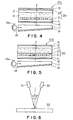
- a wavelength-selecting optical element 20 in a preferred embodiment of the present invention includes a cholesteric layer 21 that reflects or transmits either of a right-handed circularly polarized light component and a left-handed circularly polarized light component in a selected wavelength band of an incident light; and a diffusing layer 22 disposed on the exit side of the cholesteric layer 21 to diffuse the circularly polarized light component reflected or transmitted by the cholesteric layer 21.
- the cholesteric layer 21 may be a color filter having pixels each having red, green and blue pixel regions. The pixel regions reflect or transmit either of a right-handed circularly polarized light component and a left-handed circularly polarized light component in a selected wavelength band of an incident light.
- the cholesteric layer 21 has cholesteric regularity.
- the cholesteric layer 21 may be formed of a polymerizable monomer, a polymerizable oligomer or a liquid crystal polymer.
- a polymerizable monomer suitable for forming the cholesteric layer 21 include a mixture of a liquid crystalline monomer and a chiral compound as mentioned in Japanese Laid-Open Patent Publication No. 258638/1995 and Published Japanese Translation No. 508882/1998 of PCT International Publication.
- Examples of a polymerizable oligomer that can be used to form the cholesteric layer 21 include a cyclic organopolysiloxane compound having a cholesteric phase such as mentioned in Japanese Laid-Open Patent Publication No. 165480/1982.
- Examples of a liquid crystalline polymer suitable for forming the cholesteric film layer 21 include a polymer having a mesogen group, which makes a polymer liquid crystalline, in a main chain, in side chains, or in both the main and side chains; a high-molecular-weight cholesteric liquid crystal having a cholesteryl group introduced into side chains; and liquid crystalline polymers as mentioned in Japanese Laid-Open Patent Publications No. 133810/1997 and No. 293252/1999.
- the diffusing layer 22 may be formed of a transparent resin, such as a cellulose resin, an acrylic resin or an epoxy resin, containing a diffusing agent of fine particles of an organic or inorganic material.
- a transparent resin such as a cellulose resin, an acrylic resin or an epoxy resin
- the difference in refractive index between the transparent resin and the diffusing agent is in the range of 0.02 to 1.0.
- the diffusing layer 22 is able to exercise a sufficient diffusing effect even if the diffusing layer 22 has the least necessary diffusing agent content.
- the diffusing layer 22 has a sufficient diffusing agent content and a uniform light diffusing characteristic.
- the diffusing agent has a particle size in the range of 5 nm to 50 ⁇ m.
- a diffusing agent having a particle size not smaller than 5 nm can be easily dispersed in the transparent resin.
- the particle size of the diffusing agent is not greater than 50 ⁇ m, the whitening of the surface of the diffusing layer 22 and the visibility of a screen, which are caused due to the projection of the particles of the diffusing agent from the surface of the diffusing layer 22, can be avoided.
- the surface of the diffusing layer 22 has a haze with respect to a direction normal to the surface in the range of 3 to 85, and the difference between the haze with respect to a direction normal to the surface and the haze with respect to oblique directions at ⁇ 60° to the normal to the surface is in the range of 0.1 to 7.
- the diffusing layer 22 has a haze below 3 with respect to a direction normal to the surface, the diffusing layer 22 does not have any diffusing property.
- the diffusing layer 22 has a haze exceeding 85, the diffusing layer 22 is excessively diffusive and becomes clouded.
- the screen of an optical display provided with the wavelength-selecting optical element 20 is unable to be illuminated in uniform brightness and images cannot be displayed in a satisfactory image quality.
- the surface of the diffusion layer 22 has a surface roughness Ra of 2 ⁇ m or below.
- the diffusing layer 22 is incorporated into a liquid crystal cell as shown in Fig. 3, it is preferable that the surface roughness Ra is 0.3 ⁇ m or below.
- the transparent resin forming the diffusing layer 22 is a cellulose resin, such as triacetyl cellulose (refractive index: 1.50), cellulose acetate propionate (refractive index: 1.47), cellulose acetate butyrate (refractive index: 1.47 to 1.50), cellulose (refractive index: 1.54), or cellulose tributyrate (refractive index: 1.48).
- particles of the diffusing agent of the diffusing layer 22 are organic particles, such as plastic beads.
- a diffusing agent having a high transparency and a refractive index meeting the foregoing condition for the difference in refractive index between the transparent resin and the diffusing agent is the most preferable.
- Suitable plastic beads are those of melamine (refractive index: 1.57), acrylic (refractive index: 1.49), acryl-styrene (refractive index: 1.54), polycarbonate, polyethylene or vinyl chloride.
- the diffusing agent may be an inorganic material, such as cerium oxide (refractive index: 1.63). If the diffusing layer 22 is formed in a liquid crystal cell, it is preferable to use an acrylic resin.
- optical display in a preferred embodiment of the present invention provided with the wavelength-selecting optical element 20 shown in Figs. 1A and 1B with reference to Fig. 2, in which the optical display is supposed to be a reflective type liquid crystal display by way of an example.
- a reflective type liquid crystal display 10A in a preferred embodiment of the present invention has a liquid crystal panel, for displaying an image by polarizing (modulating) a light, including a back glass substrate 11, a front glass substrate 12 disposed opposite to the back glass substrate 11, and a liquid crystal layer 13 sandwiched between the glass substrates 11 and 12.
- An absorption plate 14 is attached to the outer surface of the back glass substrate 11.
- a polarizing plate 15 is attached to the outer surface of the front glass substrate 12 facing the user.
- the absorption plate 14 may be disposed between the back glass substrate 11 and the cholesteric layer 21.
- a cholesteric layer 21 is contiguous with the inner surface of the back glass substrate 11.
- a diffusing layer 22 is sandwiched between the front glass substrate 12 and the polarizing plate 15.
- the cholesteric layer 21 and the diffusing layer 22 are placed on the optical path of the light penetrating a liquid crystal display device including the glass substrates 11 and 12 and the liquid crystal layer 13.
- the cholesteric layer 21 and the diffusing layer 22 form the wavelength-selecting optical element 20.
- the respective inner surfaces of the back glass substrate 11 and the front glass substrate are provided with TFTs (thin-film transistors), not shown, and pixel electrodes, not shown, formed by processing an ITO film.
- a liquid mixture prepared by mixing a polymerizable monomer or a polymerizable oligomer having cholesteric regularity, a photoporimerization initiator, and a chiral agent for red pixel regions is spread on the inner surface of the back glass substrate 11 by a spin coating process in a red cholesteric film.
- the red cholesteric film is exposed to ultraviolet rays for a predetermined time through a red pixel region forming mask for hardening, and unnecessary parts of the red cholesteric film were removed to form red pixel regions "R".
- a liquid mixture containing a chiral agent for green pixel regions is spread on the inner surface of the back glass substrate 11 by a spin coating process in a green cholesteric film, the green cholesteric film is patterned to form green pixel regions "G" .
- a liquid mixture containing a chiral agent for blue pixel regions is spread on the inner surface of the back glass substrate 11 by a spin coating process in a blue cholesteric film, the blue cholesteric is patterned to form blue pixel regions "B" .
- the cholesteric layer 21 as a color filter having the red pixel regions "R”, the green pixel regions "G” and the blue pixel regions "B" is completed.
- a liquid mixture of a transparent resin, such as a transparent cellulose resin, and a diffusing agent of fine particles of an organic or inorganic material is spread in a film on the outer surface of the front glass substrate 12 having the inner surface coated with an ITO film, not shown, by a spin coating process to from the diffusing layer 22.
- the glass substrates 11 and 12 are superposed with a spacer held therebetween so as to form a space therebetween.
- a liquid crystal is poured into the space between the glass substrates 11 and 12 to form the liquid crystal layer 13.
- the absorbing plate 14 is attached to the outer surface of the back glass substrate 11, and the polarizing plate 15 is attached to the outer surface of the front glass substrate 12 to complete the reflective type liquid crystal display 10A.
- the wavelength-selecting optical element 20 includes, in combination, the cholesteric layer 21 that reflects either of a right-handed circularly polarized light component and a left-handed circularly polarized light component in a selected wavelength band of an incident light, and the diffusing layer 22 disposed on the front side of the cholesteric layer 21 to diffuse the circularly polarized light component reflected by the cholesteric layer 21. Therefore, an outgoing light emerging from the wavelength-selecting optical element 20 and viewed from a direction at a viewing angle ⁇ is a mixture of light waves of optional wavelengths, so that the change of the wavelength ⁇ 0 of the outgoing light dependent on the viewing angle ⁇ can be effectively suppressed. Accordingly, the reflective type liquid crystal display 10A provided with this wavelength-selecting optical element 20 is capable of preventing the change of hues of colors of displayed images according to the viewing angle ⁇ and of displaying images in an improved image quality.
- the diffusing layer 22 diffuses the circularly polarized light component reflected by the cholesteric layer 21
- the reflective type liquid crystal display 10A provided with the wavelength-selecting optical element 20 permits image observation from a direction at a large viewing angle, and suppresses boundary reflection attributable to the difference in refractive index between the component layers of the reflective type liquid crystal display 10A, that spoiling the visibility of displayed images can be effectively prevented.
- both the cholesteric layer 21 and the diffusing layer 22 of the wavelength-selecting optical element 20 are formed on the inner surface of the back glass substrate 11.
- each of the transmissive type liquid crystal displays 10C and 10D is provided with a light guide 17 that receives light through a side surface and emits light through the upper surface, a light source 19 that emits light toward the side surface of the light guide 17, and a reflecting plate 18 attached to the back surface of the light guide 17 to reflect light fallen on the back surface of the light guide 17.
- a reflecting plate 19a is disposed behind the light source 19.
- a polarizing plate 16 is attached to the outer surface of a back glass substrate 11.
- the cholesteric layer 21 of the wavelength-selecting optical element 20 does not need necessarily to be formed on the inner surface of the back glass substrate 11.
- Both the cholesteric layer 21 and the diffusing layer 22 may be formed on the inner surface of a front glass substrate 12.
- a reflective type liquid crystal display in an example of the reflective type liquid crystal display 10A shown in Fig. 2 was fabricated.
- a cholesteric layer included in a wavelength-selecting optical element was formed of a material containing a polymerizable monomer.
- a 3 ⁇ m thick film of a liquid mixture of a composition specified below was formed on a glass substrate by spreading the liquid mixture on a glass substrate by a spin coating process in a film, drying the film, and orienting the film at 80°C.
- the film was exposed to ultraviolet rays of an intensity of 5 mW/cm 2 for 5 seconds through a red pixel region forming mask for hardening, and unnecessary parts of the film was removed to form red pixel regions "R".
- Toluene 100 parts by weight.
- green pixel regions "G” were formed by spreading a liquid mixture of a composition similar to the foregoing composition except that chiral agent content was 5 parts by weight instead of 3 parts by weight, and patterning a polymerized film of the liquid mixture.
- blue pixel regions "B” were formed similarly by spreading a liquid mixture of a composition similar to the foregoing composition except that chiral agent content was 6 parts by weight instead of 3 parts by weight, and patterning a polymerized film of the liquid mixture to complete a cholesteric layer (color filter) having the red pixel regions "R", the green pixel regions "G” and the blue pixel regions "B".
- a diffusing layer of the wavelength-selecting optical element was formed of a cellulose resin containing a diffusing agent of fine particles of an organic material.
- a 10 ⁇ m thick diffusing layer was formed on a surface of a front glass substrate opposite to a surface of the same coated with an ITO film by spreading a liquid of the following composition in a film by a gravure coating process, drying the film and heating the dried film at 100°C.
- Cellulose-acetate-propionate resin (refractive index: 1.50) ("CELLIDOR CP", Bayer): 100 parts by weight Melamine beads (refractive index: 1.57, Mean particle size: 1.2 ⁇ m) ("EPOSTAR", Nippon Shokubai K.K.): 3.89 parts by weight Toluene: 1000 parts by weight
- the diffusing layer thus formed on the front glass substrate had a haze of 30 with respect to a direction normal to its surface.
- the difference between the haze with respect to a direction normal to the surface and the haze with respect to oblique directions at ⁇ 60° to the normal to the surface was 3.
- the surface roughness Ra of the diffusing layer 22 was 0.3 ⁇ m.
- the glass substrates respectively provided with the cholesteric layer and the diffusing layer were superposed with a spacer held therebetween so as to form a space therebetween.
- a liquid crystal was poured into the space between the glass substrates to form the liquid crystal layer.
- an absorbing plate was attached to the outer surface of the back glass substrate, and a polarizing plate was attached to the outer surface of the front glass substrate to complete the reflective type liquid crystal display as shown in Fig. 2.
- a reflective type liquid crystal display in a comparative example was fabricated.
- the reflective type liquid crystal display in the comparative example was identical with the foregoing reflective type liquid crystal display in the example, except that the former was not provided with any layer corresponding to the diffusing layer of the latter.
- the reflective type liquid crystal display in the comparative example was subjected to the measurement of color reproducing regions (Measurement 1) and the measurement of color variation with a viewing angle (Measurement 2).
- a measuring device shown in Fig. 6 was used for measuring color reproducing regions.
- Light (unpolarized light) emitted by a light source (D65 light source) 31 was projected on the surface of a test sample 30, i.e., the reflective type liquid crystal display in the example or the comparative example, at an incident angle of 5°. Reflected light (polarized light) reflected at a reflection angle of 5° was detected by a detector 32.
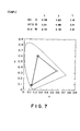
- Figs. 7 and 8 are chromaticity diagrams showing measured color reproducing regions of the example and the comparative example, respectively.
- apexes of a triangle represent the respective chromaticity coordinates of red, green and blue reproduced by the red, the green and the blue pixel regions of the cholesteric layer.
- the color reproducing regions (color purities) of the test sample 30 of the example and the test sample 30 not provided with a diffusing layer of the comparative example were substantially identical.
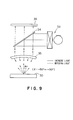
- a measuring device shown in Fig. 9 was used for measurement.
- Light (unpolarized light) emitted by a diffusion light source 33 was reflected by a semitransparent mirror 34 toward a Fourier lens 35 to make the light fall on a test sample 30 of the example or the comparative example at an incident angle ⁇ in the range of -80° to +80°.
- Reflected light reflected by the test sample 30 at a reflection angle ⁇ in the range of -50° to +50° was guided by the Fourier lens 35 and the semitransparent mirror 34 to a CCD sensor 36 to measure chromaticity coordinates for each reflection angle ⁇ .
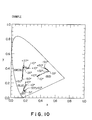
- Figs. 10 and 11 are chromaticity diagrams representing modes of color shift for the example and the comparative example.
- chromaticity coordinates of red, green and blue reproduced by the red, the green and the blue pixel regions of the cholesteric layer are plotted for reflection angles ⁇ .
- test samples 30 of the example and the comparative example were observed visually.
- the present invention is capable of preventing the change of hues of colors of displayed images dependent on viewing direction to improve image quality.
Landscapes
- Physics & Mathematics (AREA)
- Nonlinear Science (AREA)
- Chemical & Material Sciences (AREA)
- Crystallography & Structural Chemistry (AREA)
- General Physics & Mathematics (AREA)
- Optics & Photonics (AREA)
- Mathematical Physics (AREA)
- Polarising Elements (AREA)
- Liquid Crystal (AREA)
- Optical Filters (AREA)
Abstract
Description
Photoporimerization initiator (IRG369, Ciba Speciality Chemicals): 3 parts by weight
Chiral agent having polymerizable acrylates at its opposite ends: 3 parts by weight
Toluene: 100 parts by weight.

Melamine beads (refractive index: 1.57, Mean particle size: 1.2 µm) ("EPOSTAR", Nippon Shokubai K.K.): 3.89 parts by weight
Toluene: 1000 parts by weight
Claims (6)
- A wavelength-selecting optical element comprising:a cholesteric layer that reflects or transmits either of a right-handed circularly polarized light component and a left-handed circularly polarized light component in a selected wavelength band of an incident light; anda diffusing layer disposed on an exit side of the cholesteric layer to diffuse the circularly polarized light component reflected or transmitted by the cholesteric layer.
- The wavelength-selecting optical element according to claim 1, wherein the cholesteric layer is a color filter including red, green and blue pixel regions.
- The wavelength-selecting optical element according to claim 1 or 2, wherein the diffusing layer is superposed on the cholesteric layer.
- An optical display comprising:a display device adapted to display an image by modulating light;a cholesteric layer disposed on an optical path for the light that penetrates the display device, the cholesteric layer being adapted to reflect or transmit either of a right-handed circularly polarized light component and a left-handed circularly polarized light component in a selected wavelength band of the light; anda diffusing layer disposed on an exit side of the cholesteric layer to diffuse the circularly polarized light component reflected or transmitted by the cholesteric layer.
- The optical display according to claim 4, wherein the display device is a liquid crystal display device.
- The optical display according to claim 4 or 5, wherein the cholesteric layer is a color filter including red, green and blue pixel regions.
Applications Claiming Priority (2)
| Application Number | Priority Date | Filing Date | Title |
|---|---|---|---|
| JP2001167293 | 2001-06-01 | ||
| JP2001167293A JP2002357717A (en) | 2001-06-01 | 2001-06-01 | Wavelength selection element and optical display device having the same |
Publications (2)
| Publication Number | Publication Date |
|---|---|
| EP1265083A2 true EP1265083A2 (en) | 2002-12-11 |
| EP1265083A3 EP1265083A3 (en) | 2005-01-19 |
Family
ID=19009700
Family Applications (1)
| Application Number | Title | Priority Date | Filing Date |
|---|---|---|---|
| EP02011676A Ceased EP1265083A3 (en) | 2001-06-01 | 2002-05-31 | Wavelength-selecting optical element and optical display provided with the same |
Country Status (5)
| Country | Link |
|---|---|
| US (2) | US7030949B2 (en) |
| EP (1) | EP1265083A3 (en) |
| JP (1) | JP2002357717A (en) |
| KR (1) | KR100515629B1 (en) |
| TW (1) | TWI235255B (en) |
Families Citing this family (26)
| Publication number | Priority date | Publication date | Assignee | Title |
|---|---|---|---|---|
| TWI289708B (en) | 2002-12-25 | 2007-11-11 | Qualcomm Mems Technologies Inc | Optical interference type color display |
| US7342705B2 (en) | 2004-02-03 | 2008-03-11 | Idc, Llc | Spatial light modulator with integrated optical compensation structure |
| US7710636B2 (en) * | 2004-09-27 | 2010-05-04 | Qualcomm Mems Technologies, Inc. | Systems and methods using interferometric optical modulators and diffusers |
| US7630123B2 (en) * | 2004-09-27 | 2009-12-08 | Qualcomm Mems Technologies, Inc. | Method and device for compensating for color shift as a function of angle of view |
| US7813026B2 (en) * | 2004-09-27 | 2010-10-12 | Qualcomm Mems Technologies, Inc. | System and method of reducing color shift in a display |
| US7508571B2 (en) * | 2004-09-27 | 2009-03-24 | Idc, Llc | Optical films for controlling angular characteristics of displays |
| US7845841B2 (en) | 2006-08-28 | 2010-12-07 | Qualcomm Mems Technologies, Inc. | Angle sweeping holographic illuminator |
| KR101460351B1 (en) | 2006-10-06 | 2014-11-10 | 퀄컴 엠이엠에스 테크놀로지스, 인크. | A display device including an optical loss structure |
| US8872085B2 (en) | 2006-10-06 | 2014-10-28 | Qualcomm Mems Technologies, Inc. | Display device having front illuminator with turning features |
| EP2069838A2 (en) * | 2006-10-06 | 2009-06-17 | Qualcomm Mems Technologies, Inc. | Illumination device with built-in light coupler |
| US20100103488A1 (en) | 2006-10-10 | 2010-04-29 | Qualcomm Mems Technologies, Inc. | Display device with diffractive optics |
| JP2008180936A (en) * | 2007-01-25 | 2008-08-07 | Nitto Denko Corp | Color purity improving sheet, optical device, image display device, and liquid crystal display device |
| US7777954B2 (en) * | 2007-01-30 | 2010-08-17 | Qualcomm Mems Technologies, Inc. | Systems and methods of providing a light guiding layer |
| US8068710B2 (en) | 2007-12-07 | 2011-11-29 | Qualcomm Mems Technologies, Inc. | Decoupled holographic film and diffuser |
| WO2009102731A2 (en) | 2008-02-12 | 2009-08-20 | Qualcomm Mems Technologies, Inc. | Devices and methods for enhancing brightness of displays using angle conversion layers |
| WO2009129264A1 (en) | 2008-04-15 | 2009-10-22 | Qualcomm Mems Technologies, Inc. | Light with bi-directional propagation |
| KR20090130760A (en) * | 2008-06-16 | 2009-12-24 | 삼성전자주식회사 | A liquid crystal display device having a viewing angle controlled by using a stripe diffuser, a manufacturing method thereof, and a stripe diffuser |
| US20090323144A1 (en) * | 2008-06-30 | 2009-12-31 | Qualcomm Mems Technologies, Inc. | Illumination device with holographic light guide |
| US8670171B2 (en) | 2010-10-18 | 2014-03-11 | Qualcomm Mems Technologies, Inc. | Display having an embedded microlens array |
| US8902484B2 (en) | 2010-12-15 | 2014-12-02 | Qualcomm Mems Technologies, Inc. | Holographic brightness enhancement film |
| WO2013066308A1 (en) * | 2011-10-31 | 2013-05-10 | Hewlett-Packard Development Company, L.P. | Diffuse cholesteric reflector |
| KR102659654B1 (en) * | 2016-09-26 | 2024-04-23 | 삼성디스플레이 주식회사 | Display apparatus |
| CN108333832B (en) * | 2018-03-05 | 2022-02-01 | 京东方科技集团股份有限公司 | Color film substrate, liquid crystal display panel and display device |
| CN110828686A (en) * | 2018-08-10 | 2020-02-21 | 咸阳彩虹光电科技有限公司 | Self-luminous display structure and display device |
| KR102813657B1 (en) * | 2019-12-20 | 2025-05-27 | 엘지디스플레이 주식회사 | Optical film and display device comprising the same |
| CN111679354A (en) * | 2020-06-05 | 2020-09-18 | Tcl华星光电技术有限公司 | Reflective filter and preparation method thereof, and reflective display device |
Family Cites Families (27)
| Publication number | Priority date | Publication date | Assignee | Title |
|---|---|---|---|---|
| DE3110048A1 (en) | 1981-03-16 | 1982-09-30 | Consortium für elektrochemische Industrie GmbH, 8000 München | "COMPOSITIONS CONTAINING LIQUID CRYSTALLINE PHASES BASED ON CYCLIC ORGANOPOLYSILOXANS, THEIR PRODUCTION AND THEIR USE" |
| US5135340A (en) * | 1991-04-10 | 1992-08-04 | Hi-Shear Corporation | Bulged and swelled blind fastener |
| US6633354B2 (en) * | 1991-11-27 | 2003-10-14 | Reveo, Inc. | Spectrum-controllable reflective polarizers having electrically-switchable modes of operation |
| TW289095B (en) * | 1993-01-11 | 1996-10-21 | ||
| DE19504224A1 (en) | 1994-02-23 | 1995-08-24 | Merck Patent Gmbh | Liq. crystalline (LC) material |
| US6573961B2 (en) | 1994-06-27 | 2003-06-03 | Reveo, Inc. | High-brightness color liquid crystal display panel employing light recycling therein |
| WO1997040410A1 (en) * | 1996-04-22 | 1997-10-30 | Nitto Denko Corporation | Circular-dichroism optical element, device therefor, and liquid crystal polymer |
| JP2998075B2 (en) * | 1996-06-20 | 2000-01-11 | セイコーインスツルメンツ株式会社 | Reflective liquid crystal display |
| JP3317158B2 (en) * | 1996-09-20 | 2002-08-26 | ミノルタ株式会社 | Reflective liquid crystal display |
| US5796454A (en) * | 1996-12-04 | 1998-08-18 | Advanced Display Systems, Inc. | Cholesteric liquid crystal display employing circular polarizer and methods of operation and manufacture therefor |
| WO1998028658A1 (en) | 1996-12-20 | 1998-07-02 | Koninklijke Philips Electronics N.V. | Reflective flat-panel color display device |
| KR100233655B1 (en) * | 1997-04-09 | 1999-12-01 | 구본준 | Color filter and manufacturing method |
| US6248259B1 (en) * | 1997-04-28 | 2001-06-19 | Nitto Denko Corporation | Optically active monomer, liquid crystal polymer, and optical element |
| WO1998050819A1 (en) * | 1997-05-07 | 1998-11-12 | Seiko Epson Corporation | Display element and electronic clock |
| JPH1123738A (en) * | 1997-07-04 | 1999-01-29 | Citizen Watch Co Ltd | Clock with solar cells |
| WO1999040480A1 (en) | 1998-02-04 | 1999-08-12 | Seiko Epson Corporation | Liquid crystal display and electronic device |
| JP2000089018A (en) | 1998-09-10 | 2000-03-31 | Toshiba Corp | Color filter and liquid crystal display |
| KR100624045B1 (en) | 1998-12-01 | 2006-09-18 | 코닌클리케 필립스 일렉트로닉스 엔.브이. | Color filter layers of cholesterically arranged materials, and reflective LCs provided with such color filter layers |
| TW539894B (en) * | 1999-02-08 | 2003-07-01 | Toshiba Corp | Planar display device |
| JP4494552B2 (en) * | 1999-06-03 | 2010-06-30 | 大日本印刷株式会社 | Transmission type liquid crystal display device |
| KR200199869Y1 (en) | 2000-05-19 | 2000-10-16 | 김석후 | The ornamental chain and the processing method thereof |
| WO2001093652A2 (en) * | 2000-06-06 | 2001-12-13 | Koninklijke Philips Electronics N.V. | Liquid crystal display device and method of manufacturing such |
| AU2001271318A1 (en) * | 2000-06-26 | 2002-01-08 | Reveo, Inc. | Cholesteric liquid crystal polarizing device |
| JP2002169026A (en) * | 2000-09-25 | 2002-06-14 | Fuji Photo Film Co Ltd | Collimator and backlight system |
| JP2002214423A (en) * | 2001-01-18 | 2002-07-31 | Fuji Photo Film Co Ltd | Method of manufacturing cholesteric liquid crystal color filter |
| JP2002350642A (en) * | 2001-05-28 | 2002-12-04 | Fuji Photo Film Co Ltd | Selective reflection film and method of manufacturing the same |
| US6876427B2 (en) * | 2001-09-21 | 2005-04-05 | 3M Innovative Properties Company | Cholesteric liquid crystal optical bodies and methods of manufacture and use |
-
2001
- 2001-06-01 JP JP2001167293A patent/JP2002357717A/en not_active Withdrawn
-
2002
- 2002-05-29 US US10/156,770 patent/US7030949B2/en not_active Expired - Fee Related
- 2002-05-30 TW TW091111587A patent/TWI235255B/en not_active IP Right Cessation
- 2002-05-31 EP EP02011676A patent/EP1265083A3/en not_active Ceased
- 2002-05-31 KR KR10-2002-0030689A patent/KR100515629B1/en not_active Expired - Fee Related
-
2006
- 2006-02-28 US US11/363,062 patent/US20060139531A1/en not_active Abandoned
Also Published As
| Publication number | Publication date |
|---|---|
| TWI235255B (en) | 2005-07-01 |
| US7030949B2 (en) | 2006-04-18 |
| US20060139531A1 (en) | 2006-06-29 |
| EP1265083A3 (en) | 2005-01-19 |
| KR100515629B1 (en) | 2005-09-20 |
| JP2002357717A (en) | 2002-12-13 |
| US20020180915A1 (en) | 2002-12-05 |
| KR20020092249A (en) | 2002-12-11 |
Similar Documents
| Publication | Publication Date | Title |
|---|---|---|
| US7030949B2 (en) | Optical display including a cholesteric layer, a display device and a diffusing layer on an exit side of the cholesteric layer | |
| KR100472894B1 (en) | Liquid crystal display device | |
| US5119220A (en) | Liquid crystal display device with a phase plate for shadow compensation | |
| EP2508940A1 (en) | Liquid crystal display device | |
| US20020176036A1 (en) | Liquid crystal display device | |
| US6407787B1 (en) | Reflective liquid crystal display device | |
| CN105467584A (en) | Member for projection image display and projection image display system | |
| US6933994B1 (en) | Liquid crystal display including an anisotropic scattering layer | |
| EP1582893A1 (en) | Broad-band-cholesteric liquid-crystal film, process for producing the same, circularly polarizing plate, linearly polarizing element, illuminator, and liquid-crystal display | |
| JP3310569B2 (en) | Reflective liquid crystal display | |
| US7355663B2 (en) | Polarizing plate and liquid crystal display using the same | |
| JP2000075132A (en) | Scattering elliptically polarizing plate and liquid crystal display | |
| JP2970541B2 (en) | Reflective LCD panel | |
| JPH11174211A (en) | Light diffusion plate, optical element and liquid crystal display device | |
| US6693686B2 (en) | Polarizing element and optical display apparatus including the same | |
| JP3467210B2 (en) | Reflective liquid crystal display | |
| US7738170B2 (en) | Projection system | |
| JP2001125105A (en) | Reflective liquid crystal display | |
| JPH06308481A (en) | Color liquid crystal display | |
| JP2005156690A (en) | Projection screen and projection system including the same | |
| JP3289391B2 (en) | Color liquid crystal display | |
| JP2004038000A (en) | Liquid crystal display device | |
| JP2003149685A (en) | Liquid crystal display | |
| US7714944B2 (en) | Projection system | |
| JP2003532930A (en) | Color-compensated information display |
Legal Events
| Date | Code | Title | Description |
|---|---|---|---|
| PUAI | Public reference made under article 153(3) epc to a published international application that has entered the european phase |
Free format text: ORIGINAL CODE: 0009012 |
|
| AK | Designated contracting states |
Kind code of ref document: A2 Designated state(s): AT BE CH CY DE DK ES FI FR GB GR IE IT LI LU MC NL PT SE TR |
|
| AX | Request for extension of the european patent |
Free format text: AL;LT;LV;MK;RO;SI |
|
| PUAL | Search report despatched |
Free format text: ORIGINAL CODE: 0009013 |
|
| AK | Designated contracting states |
Kind code of ref document: A3 Designated state(s): AT BE CH CY DE DK ES FI FR GB GR IE IT LI LU MC NL PT SE TR |
|
| AX | Request for extension of the european patent |
Extension state: AL LT LV MK RO SI |
|
| 17P | Request for examination filed |
Effective date: 20050414 |
|
| 17Q | First examination report despatched |
Effective date: 20050530 |
|
| AKX | Designation fees paid |
Designated state(s): AT BE CH CY DE DK ES FI FR GB GR IE IT LI LU MC NL PT SE TR |
|
| STAA | Information on the status of an ep patent application or granted ep patent |
Free format text: STATUS: THE APPLICATION HAS BEEN REFUSED |
|
| 18R | Application refused |
Effective date: 20071206 |