EP1264999B1 - Mécanisme à libération controlée par un effet thermique - Google Patents
Mécanisme à libération controlée par un effet thermique Download PDFInfo
- Publication number
- EP1264999B1 EP1264999B1 EP02291414A EP02291414A EP1264999B1 EP 1264999 B1 EP1264999 B1 EP 1264999B1 EP 02291414 A EP02291414 A EP 02291414A EP 02291414 A EP02291414 A EP 02291414A EP 1264999 B1 EP1264999 B1 EP 1264999B1
- Authority
- EP
- European Patent Office
- Prior art keywords
- fact
- structural elements
- threads
- melting point
- low
- Prior art date
- Legal status (The legal status is an assumption and is not a legal conclusion. Google has not performed a legal analysis and makes no representation as to the accuracy of the status listed.)
- Expired - Lifetime
Links
Images


Classifications
-
- F—MECHANICAL ENGINEERING; LIGHTING; HEATING; WEAPONS; BLASTING
- F15—FLUID-PRESSURE ACTUATORS; HYDRAULICS OR PNEUMATICS IN GENERAL
- F15B—SYSTEMS ACTING BY MEANS OF FLUIDS IN GENERAL; FLUID-PRESSURE ACTUATORS, e.g. SERVOMOTORS; DETAILS OF FLUID-PRESSURE SYSTEMS, NOT OTHERWISE PROVIDED FOR
- F15B15/00—Fluid-actuated devices for displacing a member from one position to another; Gearing associated therewith
- F15B15/19—Pyrotechnical actuators
-
- B—PERFORMING OPERATIONS; TRANSPORTING
- B64—AIRCRAFT; AVIATION; COSMONAUTICS
- B64G—COSMONAUTICS; VEHICLES OR EQUIPMENT THEREFOR
- B64G1/00—Cosmonautic vehicles
- B64G1/22—Parts of, or equipment specially adapted for fitting in or to, cosmonautic vehicles
- B64G1/222—Parts of, or equipment specially adapted for fitting in or to, cosmonautic vehicles for deploying structures between a stowed and deployed state
- B64G1/2228—Parts of, or equipment specially adapted for fitting in or to, cosmonautic vehicles for deploying structures between a stowed and deployed state characterised by the hold-down or release mechanisms
-
- B—PERFORMING OPERATIONS; TRANSPORTING
- B64—AIRCRAFT; AVIATION; COSMONAUTICS
- B64G—COSMONAUTICS; VEHICLES OR EQUIPMENT THEREFOR
- B64G1/00—Cosmonautic vehicles
- B64G1/22—Parts of, or equipment specially adapted for fitting in or to, cosmonautic vehicles
- B64G1/64—Systems for coupling or separating cosmonautic vehicles or parts thereof, e.g. docking arrangements
- B64G1/645—Separators
- B64G1/6455—Pyrotechnics; Using heat
-
- F—MECHANICAL ENGINEERING; LIGHTING; HEATING; WEAPONS; BLASTING
- F16—ENGINEERING ELEMENTS AND UNITS; GENERAL MEASURES FOR PRODUCING AND MAINTAINING EFFECTIVE FUNCTIONING OF MACHINES OR INSTALLATIONS; THERMAL INSULATION IN GENERAL
- F16D—COUPLINGS FOR TRANSMITTING ROTATION; CLUTCHES; BRAKES
- F16D9/00—Couplings with safety member for disconnecting, e.g. breaking or melting member
- F16D9/02—Couplings with safety member for disconnecting, e.g. breaking or melting member by thermal means, e.g. melting member
Definitions
- the present invention relates to the field of release controlled by a thermal effect.
- the present invention relates in particular, but not exclusively, the pyromechanisms, ie the domain of mechanisms controlled by a pyrotechnic effect.
- US-3454286 discloses a mechanism comprising two concentric inner and outer tubes including ribs protruding into the internal space defined between the two tubes, a material fuse placed in said gap between the two tubes, a material fuel that fills at least a portion of the central space of the tube internal and adapted means for initiating said combustible material in order to ensure melting of the fusible material and thus to release mechanically both tubes.
- the present invention now aims to propose a device having properties superior to those of prior devices known.
- the present invention is intended in particular to propose a device having at rest a high mechanical strength.
- the low-melting material is disposed at least on a part of the interface between means to complement form to ban the release of the blocking means, and consequently the elements of structure, before melting said material.
- Structural elements 100 and 200 may be subject to many embodiments.
- these two elements 100 and 200 are formed globally of concentric cylindrical structures centered on an O-O axis and they are otherwise susceptible to relative translation along the O-O axis after release of the locking means 300.
- the element 100 has the general shape of a rod central, while the element 200 has the general shape of a shirt cylindrical which partially surrounds the rod 100.
- the element 200 is formed by assembling different parts 202, 204, 206, 208, 210.
- the invention is not limited to this particular geometry. Said items 202 to 210 will not be therefore not described in more detail later.
- the pieces 202 to 210 define a closed chamber 220 on one end of the rod 100.
- the structure thus formed can constitute a jack type assembly in which the rod 100 forms a piston capable of relative translation controlled with respect to the jacket 200 which forms a cylinder body.
- Sealing means such as O-rings, can be inserted between the two elements 100 and 200.
- Such means of sealing can be accommodated for example in annular grooves 130, 230, 232 formed in one or other of the two elements 100, 200 and leading to the interface between them.
- the invention is however not limited to devices in which the two structural elements are only likely to relative translation.
- the translation movement of the rod 100 can be replaced or transformed into any other movement appropriate, for example an oblique movement or a movement relative to rotation relative to the element 200, using a screw / nut system or equivalent.
- the nets 310 are provided on the outer surface of a section of the rod 100.
- Tapping 320 is provided on the inner surface of a nut 340.
- the element 200 is in bearing against the nut 340, via a spacer 240.
- the spacer 240 is formed of a sleeve centered on the axis O-O.
- the material with a low melting point 330 can be the object of numerous embodiments.
- the use of a metal to form the material 330 leads to a brazing of the nut 340.
- the invention is not limited to a metal.
- the 330 material may be formed of any other thermally fusible material capable of the same function, for example a paraffin-based material or a eutectic alloy.
- the threads 310 and the complementary tapping 320 are formed of reversible nets, ie nets having a not sufficient for traction on the nut 340 and / or on the rod 100 is driving.
- the heating element capable of effecting the fusion on demand material 330 may be subject to many embodiments.
- it is a block of pyrotechnic material 150 integrated into the structure.
- the pyrotechnic material 150 is placed in an axial blind chamber 152 formed in the rod 100 and which leads into the room 220.
- the nut 340 is blocked on the rod 100 by the material 330.
- the jacket 200 bears against the spacer 240, itself in support against the nut 340.
- the rod 100 can not be urged towards the outside of the 200, to the left, relative to the jacket 200, according to the illustration given in Figure 1.
- composition pyrotechnic 150 or any equivalent heating means.
- a displacement of the rod 100 relative to the nut 340 and to the shirt 200 is then possible under the effect of a suitable driving force.
- This can be formed by the gases developed by the composition pyrotechnic 150 itself in room 220.
- the material 330 is laminated to the level of the interface between the threads 310 and the tapping 320.
- This rolling can slow down the relative movement between elements 100 and 200. This gives a controlled release of mechanical stresses of the structure.
- FIG. 3 illustrates an embodiment variant designed specifically to enhance a braking effect by rolling the 330 material, when the latter melts.
- the rod 100 in engagement, by a thread 310/320 initially blocked by a material 330 embedding the threads, with the nut 340.
- the illustrated nut in FIG. 3 defines a housing 342 able to house a reserve 331 of material 330, which housing 342 opens on the outside through a passage 343.
- the housing 342 is defined in part by a said recess formed on the rod 100.
- the spacer is used to thermally insulate the shirt 200 outside the area of the pyrotechnic composition 150 likely to be raised to high temperature.
- the present invention finds in particular, but not exclusively application in the field of the space industry, for example on launchers or satellites.
- means can be provided which avoid relative rotation between the spacer 240 and the nut 340 during the implementation of the device.
- such means may be formed of two superimposed nuts, of not inverted: 340 and 345.
- a first nut 340 is in contact with the nets 310 of the rod 100. It is itself equipped with nets on its surface the second nut 345. The latter serves as a support for the spacer 240.
- the threads of the two nuts 340 and 345 are initially blocked with a low melting point material.
- the footsteps of both nuts 340 and 345 may be identical. However this characteristic is not imperative.
- a ball bearing or equivalent may be interposed between the nut 340 and the spacer 240.
- the combination of the low melting point material 330 and the fillets 310/320 makes it possible to benefit, in the context of the present invention, from a high mechanical strength, at rest of the device.
- FIG. 4 illustrates a variant embodiment in which we find the rod 100 in threaded connection 310/320 with a nut 340 defining a housing 342 capable of receiving a reserve 331 of material 330 low melting point.
- the 330 material that blocks the mount is not placed at the level of the nets 310/320, but at an interface 350, cylindrical of revolution, formed between the outer surface of the rod 100 and the inner surface of the nut 340, on a separate section of the nets 310/320.
- FIG. 5 illustrates another variant embodiment which one finds the rod 100 in threaded connection 310/320 with a nut 340.
- the nut 340 does not define a reserve for the low-point material of as is the case in Figures 3 and 4.
- the material 330 which blocks the assembly is not placed at the level of the 310/320 nets, but at the level an interface 350, cylindrical of revolution, formed between the surface external of the rod 100 and the inner surface of the nut 340, on a section separate from the 310/320 nets.
- the device comprises two elements 100, 200 capable of relative rotation around the O-O axis.
- the element 100 is formed of a hollow cylindrical rod. This one is immobilized in translation relative to the element 200, but free of rotation around the axis O-O with respect to this same element 200.
- the rod 100 is supported on one side on a spacer 240 itself linked by rotation and translation with the element 200.
- the bond defined between the spacer 240 and the element 200 can be defined by any appropriate means.
- the spacer 240 is immobilized in translation by pinch between two bodies 2010, 2020 constituting the bulk of the second 200.
- the spacer 240 is preferably immobilized at rotation relative to the body 200 by means of a pin 242, for example oriented parallel to the O-O axis and interferes with both the spacer 240 and the element 200.
- the hollow cylindrical rod 100 is in support of the other side on a flange 2014 of the element 200.
- Figure 7 a game between the rod 100 and the flask 2014, under the reference 2015.
- the game or housing thus formed is filled in practice by a bearing or any equivalent means facilitating a relative rotation between the rod 100 and the element 200.
- the element 200 can be the object of numerous geometries and variants of embodiment.
- the element 200 is formed by assembling two body 2010 and 2020 using a nut or equivalent 2030.
- each of these two bodies 2010, 2020 includes a cylindrical envelope 2012, 2022 centered on the O-O axis, complemented respectively by an end plate 2014, 2024 perpendicular to the axis O-O.
- the 2014 flange has a central passage through which the rod 100 is designed to move.
- the sealing means can be provided at the interface between the flange 2014 and the rod 100. It may be for example an O-ring or any equivalent means positioned in a ring groove 2016 formed on the flask 2014.
- the flange 2014 preferably has an outer flange 2017 provided with a plurality of through holes 2018 designed for ensure the fixation of the device.
- the flask 2014 is designed to carry at least one initiator (the latter being not shown to simplify the illustration).
- the flange 2024 has two housings 2025, 2026 designed to each receive an initiator, so redundancy and reliability effect.
- the device illustrated on illustrated in Figures 6 and 7 attached further comprises a piston 3000 disposed inside the element 200 and interposed in series operation between the two elements 100 and 200.
- the piston 3000 comprises a drum 3010 integral with a collar 3020.
- the 3010 drum is designed to be engaged in a central channel of the element 100 to allow both translation and relative rotation between these elements.
- the shaft 3010 itself has a blind central housing which leads to flange 2024 and receives a pyrotechnic composition strongly exothermic 150.
- the aforementioned flange 3020 of the piston 3000 is adjacent to the flange 2024. It ensures a seal between the piston 3000 and the body 200 thanks any appropriate means, for example by means of an O-ring engaged in a peripheral annular groove 3022 formed on the outer surface of the collar 3020.
- the 3000 piston has a series of external threads on a stretch 3100. These are adapted to cooperate with means complementary 180 linked to the rod 100 to transform a movement of translation of the piston 3000 along the axis O-O in a rotational movement of the rod 100, about the axis O-O, relative to the piston 3000.
- the means 180 provided for this purpose on the rod 100 can be formed of a tapping.
- this is preferably at least one finger 182 oriented radially with respect to the axis O-O, engaged with the rod 100 and engaged in the nets 3100.
- the aforementioned three fingers 182 are mounted in radial sliding in a complementary radial bore formed on the rod 100.
- the piston 3000 further comprises a second set of threads on a section 3200. These are adapted to cooperate with means complementary 2400 linked to the spacer 240 and to the body 200.
- Threads 3200 have a reverse pitch of nets 3100.
- the aforementioned means 2400 provided for this purpose on the spacer 240 may be formed of a tapping. However, it is preferably from minus one finger 2402 oriented radially with respect to the axis O-O, engaged with the spacer 240 and engaged in the nets 3200.
- the 2402 fingers are mounted to radial sliding in a complementary radial bore formed in the spacer 240.
- the device illustrated in FIGS. 6 and 7 further comprises a massage of low melting point material 330 forming solder between the piston 3000 and the spacer 240.
- This mass 330 of low-point material melting is placed in a housing 332 formed between the piston 3000 and the spacer 240.
- this housing 332 is formed of a throat device on the outer surface of the piston 3000 between the two sections of nets 3100 and 3200.
- the device can be completed by a ring 2500 (or more precisely two half complementary rings 2510 for manufacturing and assembly) immobilized at least in translation by pinching between the spacer 240 and the rod 100 and disposed on one end of the housing 332.
- this ring 2500 imposes a rolling the low melting point material 330 during processing of the device, since during a translation of the piston 3000 along the axis O-O relative to the element 200, the low melting point material 330 is forced to cross the ring 2500 by the calibrated passage of small dimension defined between the ring 2500 and the outer surface of the piston 3000.
- At least one of the initiators placed in cavities 2025 or 2026 is activated. Initiation is thus transmitted to the pyrotechnic composition 150.
- the material 330 has low melting point reaches its point of softening.
- the piston 3000 is thus released with respect to the spacer 240 and the element 200.
- the gases generated by the initiators placed in the cavities 2025 or 2026, or by the pyrotechnic composition 150, or still any other adequate external means solicits the piston 3000 to translation along the O-O axis (to the right according to the representation of the figure 7).
- This displacement is braked by rolling of the solder material 330 when crossing the 2500 ring.
- the cooperation defined between the nets 3200 and the fingers 2402 transforms the translational movement of the piston 3000 along the axis O-O a rotational movement around this same axis.
- the translation of the piston 3000 is transformed by the defined cooperation between the nets 3100 and 182 fingers in one motion relative rotation of the rod 100.
- Such a device can give rise to many uses.
Landscapes
- Engineering & Computer Science (AREA)
- General Engineering & Computer Science (AREA)
- Aviation & Aerospace Engineering (AREA)
- Mechanical Engineering (AREA)
- Remote Sensing (AREA)
- Analytical Chemistry (AREA)
- Fluid Mechanics (AREA)
- Chemical & Material Sciences (AREA)
- Physics & Mathematics (AREA)
- Actuator (AREA)
- Automotive Seat Belt Assembly (AREA)
- Mechanical Control Devices (AREA)
- Temperature-Responsive Valves (AREA)
- Mechanical Operated Clutches (AREA)
- Transmission Devices (AREA)
Description
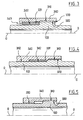
- la figure 1 représente une vue schématique, en coupe axiale longitudinale, d'un dispositif conforme à un mode de réalisation préférentiel de la présente invention,
- la figure 2 représente une vue partielle similaire, en coupe axiale longitudinale, d'une variante de réalisation conforme à la présente invention,
- les figures 3, 4, et 5 représentent trois variantes de réalisation conformes à la présente invention, et
- la figure 6 représente une vue en perspective éclatée d'une autre variante de réalisation conforme à la présente invention, tandis que la figure 7 représente une vue en coupe longitudinale de cette même variante.
- un premier élément de structure 100,
- un deuxième élément de structure 200 et
- un moyen de blocage 300.
- d'au moins un ensemble comprenant des moyens à complément de forme formés avantageusement par, d'une part des filets 310 et d'autre part un taraudage complémentaire 320, liés respectivement aux deux éléments de structure 100 et 200, et
- d'un matériau 330 à bas point de fusion disposé au moins sur une partie de l'interface entre les filets 310 et le taraudage complémentaire 320 pour interdire la libération du moyen de blocage 300, et par conséquent des éléments de structure 100 et 200, avant fusion dudit matériau 330.
- Bi50/Pb28/Sn22 (pour une température de fusion de l'ordre de 95-110°C) ou
- In (pour une température de fusion de l'ordre de 156°C) ou
- Sn ou Sn85/Zn15 (pour une température de fusion de l'ordre de 200-250°C) ou
- Pb82,5/Cd17,5 ou
- Pb96/Sb4 (pour une température de fusion de l'ordre de 250-300°C).
- Al + Fe2O3 ou
- Mg + Fe2O3 ou
- Al + CuO ou
- Mg + CuO.
Claims (21)
- Dispositif formant mécanisme à libération contrôlée, comprenant :un matériau à bas point de fusion (330) disposé au moins sur une partie de l'interface (310/320, 350) entre deux pièces liées respectivement aux deux éléments de structure (100, 200) pour interdire la libération du moyen de blocage (300), et par conséquent des éléments de structure (100, 200), avant fusion dudit matériau, caractérisé par le fait que le moyen de blocage comprend au moins un ensemble comprenant des moyens à complément de forme, de configuration hélicoïdale (310, 320), liés respectivement aux deux éléments de structure (100, 200), que les moyens à complément de forme, de configuration hélicoïdale comprennent d'une part des filets (310), et d'autre part un taraudage (320) complémentaire liés respectivement aux deux éléments (100, 200) et que les filets (310) et le taraudage complémentaire (320) sont formés de filets réversibles, c'est à dire de filets possédant un pas suffisant pour qu'une traction soit motrice, après fusion du matériau à bas point de fusion (330).deux éléments de structure (100, 200) susceptibles de déplacement relatif, etun moyen de blocage (300) apte à interdire initialement le déplacement relatif entre les deux éléments de structure (100, 200), lequel moyen de blocage (300) comprend
- Dispositif selon la revendication 1, caractérisé par le fait que le matériau à bas point de fusion (330) est disposé au moins sur une partie de l'interface entre les moyens à complément de forme (310, 320) pour interdire la libération du moyen de blocage, et par conséquent des éléments de structure (100, 400), avant fusion dudit matériau (330).
- Dispositif selon l'une des revendications 1 ou 2, caractérisé par le fait que le taraudage (320) est formé sur un écrou (340).
- Dispositif selon l'une des revendications 1 à 3, caractérisé par le fait qu'une entretoise (240) est intercalée entre l'un des éléments de structure (200) et le moyen de blocage (300).
- Dispositif selon l'une des revendications 1 à 4, caractérisé par le fait que le matériau à bas point de fusion (330) est formé d'un métal.
- Dispositif selon la revendication 5, caractérisé par le fait que le matériau à bas point de fusion (330) est choisi dans le groupe comprenant :Bi50/Pb28/Sn22 (pour une température de fusion de l'ordre de 95-110°C) ouIn (pour une température de fusion de l'ordre de 156°C) ouSn ou Sn85/Zn15 (pour une température de fusion de l'ordre de 200-250°C) ouPb82,5/Cd17,5 ouPb96/Sb4 (pour une température de fusion de l'ordre de 250-300°C).
- Dispositif selon l'une des revendications 1 à 4, caractérisé par le fait que le matériau à bas point de fusion (330) est formé d'un matériau à base de paraffine ou d'un alliage eutectique.
- Dispositif selon l'une des revendications 1 à 7, caractérisé par le fait qu'il comprend en outre un moyen de chauffage (150) apte à provoquer sélectivement la fusion du matériau à bas point de fusion (330).
- Dispositif selon la revendication 8, caractérisé par le fait que l'élément de chauffage (150) est formé d'un matériau pyrotechnique (150) intégré dans la structure.
- Dispositif selon l'une des revendications 1 à 9, caractérisé par le fait que les deux éléments de structure (100, 200) sont susceptibles de translation relative.
- Dispositif selon l'une des revendications 1 à 10, caractérisé par le fait qu'il comprend des moyens (340, 345) évitant une rotation relative entre le moyen de blocage (300) et l'un des éléments de structure (200) lors de la mise en oeuvre du dispositif.
- Dispositif selon la revendication 11, caractérisé par le fait que les moyens (340, 345) évitant une rotation relative comprennent deux écrous en prise superposés, de pas inversés (340, 345).
- Dispositif selon la revendication 11, caractérisé par le fait que les moyens (340, 345) évitant une rotation relative comprennent un roulement à billes ou équivalent.
- Dispositif selon l'une des revendications 1 à 9, caractérisé par le fait que les deux éléments de structure (100, 200) sont susceptibles de rotation relative.
- Dispositif selon la revendication 14, caractérisé par le fait qu'il comprend un piston (3000) susceptible de translation par rapport aux éléments de structure (100, 200) et muni de filets (3100) en prise avec des moyens (182) liés à un élément de structure (100).
- Dispositif selon la revendication 15, caractérisé par le fait que le piston (3000) comprend en outre une seconde série de filets (3200) en prise avec des moyens (2402) liés au second élément de structure (200).
- Dispositif selon la revendication 16, caractérisé par le fait que les deux séries de filets (3100, 3200) ont des pas inversées.
- Dispositif selon l'une des revendications 14 à 17, caractérisé par le fait que les moyens (182, 2402) en prise avec les filets (3100, 3200) comprennent au moins un doigt radial.
- Dispositif selon l'une des revendications 15 à 18, caractérisé par le fait que les filets (3100, 3200) sont formés de doigts radiaux solidaires du piston (3000).
- Dispositif selon l'une des revendications 1 à 19, caractérisé par le fait que l'un au moins des éléments de structure (100, 400) définit un logement (342) apte à loger une réserve (331) de matériau (330) à bas point de fusion, lequel logement (342) débouche sur l'extérieur par un passage de section calibrée (343) et est adapté pour réduire son volume lors d'un déplacement relatif entre les éléments de structure (100, 200) de sorte que ce déplacement entraíne un laminage du matériau (330) par le passage (343).
- Dispositif selon l'une des revendications 1 à 20, caractérisé par le fait qu'il comprend du matériau (330) à bas point de fusion au niveau d'une interface (350) différente des filets (310/320).
Applications Claiming Priority (2)
| Application Number | Priority Date | Filing Date | Title |
|---|---|---|---|
| FR0107558 | 2001-06-08 | ||
| FR0107558A FR2825766B1 (fr) | 2001-06-08 | 2001-06-08 | Mecanisme a liberation controlee par un effet thermique |
Publications (3)
| Publication Number | Publication Date |
|---|---|
| EP1264999A2 EP1264999A2 (fr) | 2002-12-11 |
| EP1264999A3 EP1264999A3 (fr) | 2004-02-25 |
| EP1264999B1 true EP1264999B1 (fr) | 2005-10-26 |
Family
ID=8864128
Family Applications (1)
| Application Number | Title | Priority Date | Filing Date |
|---|---|---|---|
| EP02291414A Expired - Lifetime EP1264999B1 (fr) | 2001-06-08 | 2002-06-07 | Mécanisme à libération controlée par un effet thermique |
Country Status (4)
| Country | Link |
|---|---|
| US (1) | US6661331B2 (fr) |
| EP (1) | EP1264999B1 (fr) |
| DE (1) | DE60206835T2 (fr) |
| FR (1) | FR2825766B1 (fr) |
Families Citing this family (20)
| Publication number | Priority date | Publication date | Assignee | Title |
|---|---|---|---|---|
| WO2002042590A1 (fr) * | 2000-11-23 | 2002-05-30 | Kim Heung Kee | Unite de charniere de porte |
| CO5840262A1 (es) * | 2006-06-27 | 2007-12-31 | Martinez Naranjo John Jairo | Conector endotermico para soldar cobre |
| FR2947808B1 (fr) * | 2009-07-09 | 2011-12-09 | Astrium Sas | Dispositif de separation lineaire douce d'une premiere piece et d'une seconde piece |
| FR2952353B1 (fr) * | 2009-11-10 | 2011-12-09 | Thales Sa | Systeme de tirant actif permettant le maintien et la liberation sans choc d'appendices spatiaux |
| DE102011079789B3 (de) * | 2011-07-26 | 2012-07-12 | Minimax Gmbh & Co. Kg | Thermotrennglied mit Schmelzlot |
| US9410596B2 (en) | 2011-11-04 | 2016-08-09 | Honeywell International Inc. | Mounting systems for structural members, fastening assemblies thereof, and vibration isolation systems including the same |
| US8678323B2 (en) | 2012-02-28 | 2014-03-25 | Honeywell International Inc. | Launch lock assemblies including axial gap amplification devices and spacecraft isolation systems including the same |
| US9475594B2 (en) | 2012-09-25 | 2016-10-25 | Honeywell International Inc. | Launch lock assemblies with reduced preload and spacecraft isolation systems including the same |
| US9546008B1 (en) * | 2014-06-17 | 2017-01-17 | The United States Of America As Represented By The Administrator Of The National Aeronautics And Space Administration | Miniature release mechanism or diminutive assembly for nanosatellite deployables (DANY) |
| RU2561424C1 (ru) * | 2014-09-24 | 2015-08-27 | Федеральное государственное бюджетное образовательное учреждение высшего профессионального образования "Петербургский государственный университет путей сообщения Императора Александра I" | Компенсирующая муфта |
| ITUB20159136A1 (it) * | 2015-12-16 | 2017-06-16 | Aerea Spa | Dispositivo per il collegamento e il rilascio comandato di satelliti spaziali installati su lanciatori e di carichi installati su satelliti spaziali |
| US9828117B2 (en) * | 2016-02-04 | 2017-11-28 | United Launch Alliance, L.L.C. | Tensioning apparatus and system for clamping joints |
| DE102016205326A1 (de) * | 2016-03-31 | 2017-10-05 | Airbus Ds Gmbh | Thermisch fragmentierbare Befestigungseinrichtung |
| AT518680B1 (de) * | 2016-06-02 | 2018-10-15 | Hirtenberger Automotive Safety Gmbh & Co Kg | Pyrotechnischer Aktuator |
| CN109625327B (zh) * | 2018-12-10 | 2022-03-18 | 上海卫星装备研究所 | 适用于真空环境的热熔断解锁释放装置 |
| CN110388350B (zh) * | 2019-07-24 | 2020-08-11 | 宁波悦威液压科技有限公司 | 一种缓冲液压缸 |
| CN115231001B (zh) * | 2022-07-27 | 2024-08-09 | 大连理工大学 | 一种非火工箭体径向连接解锁装置及使用方法 |
| CN116215896B (zh) * | 2022-12-30 | 2023-08-18 | 中国科学院空间应用工程与技术中心 | 一种在线柜用旋转平台以及操作箱 |
| DE102024109240B3 (de) * | 2024-04-02 | 2025-08-14 | Deutsches Zentrum für Luft- und Raumfahrt e.V. | Verbindungseinrichtung |
| DE102024001857B4 (de) * | 2024-06-07 | 2026-02-12 | Invent Innovative Verbundwerkstoffe Realisation Und Vermarktung Neuer Technologien Gmbh | Raumfahrzeug und Trennmechanismus für ein Raumfahrzeug |
Family Cites Families (35)
| Publication number | Priority date | Publication date | Assignee | Title |
|---|---|---|---|---|
| GB1011680A (en) * | 1963-04-18 | 1965-12-01 | Westland Aircraft Ltd | Improvements in or relating to load releasing devices |
| US3359804A (en) * | 1965-10-11 | 1967-12-26 | Gray & Huleguard | Mechanical actuator package |
| US3454286A (en) * | 1967-03-01 | 1969-07-08 | Us Navy | Thermally operated release mechanism |
| US3597809A (en) * | 1969-08-11 | 1971-08-10 | Rixson Inc | Separating link |
| US3613795A (en) * | 1969-08-13 | 1971-10-19 | Air Balance | Electrically and/or thermally actuated release link |
| US3695116A (en) * | 1970-09-30 | 1972-10-03 | Bunker Ramo | Non-explosive electrically initiated heat-ignitable actuator |
| US3779004A (en) * | 1972-09-12 | 1973-12-18 | Star Sprinkler Corp Of Florida | Fusible link |
| US3863720A (en) * | 1974-03-13 | 1975-02-04 | Richard J Young | Electrical resistance fusible link for a sprinkler head |
| US4055829A (en) * | 1975-03-03 | 1977-10-25 | Elsie Manufacturing Company | Fusible links and process for producing same |
| FR2382902A1 (fr) * | 1977-03-07 | 1978-10-06 | Farcinade Michel | Dispositif liberateur temporise ou non, automatique ou manuel de ceinture de securite |
| US4501058A (en) * | 1979-08-27 | 1985-02-26 | Pda Engineering | Method of pre-stressing a structural member |
| US4346554A (en) * | 1979-11-13 | 1982-08-31 | Globe Fire Equipment Company | Fusible link construction |
| US4532681A (en) * | 1981-03-23 | 1985-08-06 | Baker Edward H | Restraining belts |
| US4442756A (en) * | 1981-08-24 | 1984-04-17 | Baker, Cac, Inc. | Heat sensitive locking device |
| US4405914A (en) * | 1981-09-18 | 1983-09-20 | Ruegsegger Donald R | Fusible links |
| DE3461685D1 (en) * | 1983-07-11 | 1987-01-29 | Leuven Res & Dev Vzw | Temperature responsive bolt element |
| US4625998A (en) * | 1984-04-02 | 1986-12-02 | Draudt Donald A | Swivel hose couplings |
| US4796420A (en) * | 1987-11-13 | 1989-01-10 | Van Wormer Management Corporation | Fusible link construction |
| US5119555A (en) * | 1988-09-19 | 1992-06-09 | Tini Alloy Company | Non-explosive separation device |
| US5245738A (en) * | 1988-09-19 | 1993-09-21 | Tini Alloy Company | Method for securing together and non-explosively separating multiple components |
| FR2648199B1 (fr) * | 1989-06-09 | 1991-09-27 | Aerospatiale | Dispositif de liaison temporaire, notamment pour appendice de satellite artificiel, et procede de liberation d'une telle liaison |
| US5122020A (en) * | 1990-04-23 | 1992-06-16 | Bedi Ram D | Self locking fastener |
| US5120152A (en) * | 1990-06-25 | 1992-06-09 | Carmen Gueli | Fusible link |
| US5248233A (en) * | 1992-09-25 | 1993-09-28 | Webster Richard G | No-shock separation mechanism |
| US5254967A (en) * | 1992-10-02 | 1993-10-19 | Nor-Am Electrical Limited | Dual element fuse |
| US5686878A (en) * | 1995-04-03 | 1997-11-11 | Gueli; Carmen | Temperature sensitive fusible link assembly having cooperating projections and slots |
| US5621373A (en) * | 1995-08-14 | 1997-04-15 | G & H Technology, Inc. | Non-explosive initiator with link wire assembly |
| US5606889A (en) * | 1995-09-19 | 1997-03-04 | G & H Technology, Inc. | Reusable initiator for use in triggering high-load actuators |
| US5695306A (en) * | 1996-05-08 | 1997-12-09 | Lockheed Martin Corp. | Fusible member connection apparatus and method |
| DE19635177A1 (de) * | 1996-08-30 | 1998-03-05 | Job Lizenz Gmbh & Co Kg | Thermisch auslösende Trennvorrichtung, insbesondere für Feuerschutzanlagen |
| US5748066A (en) * | 1996-09-09 | 1998-05-05 | G & H Technology, Inc. | Cartridge motion initiator with replaceable link wire controller |
| IT237848Y1 (it) * | 1997-08-04 | 2000-09-29 | Waircom M B S S P A | Cilindrico pneumatico con albero non rotante |
| US6404322B1 (en) * | 1999-02-12 | 2002-06-11 | Elsie Manufacturing Company, Inc. | Fusible link |
| US6133818A (en) * | 1999-08-11 | 2000-10-17 | Space Systems/Loral, Inc. | Redundant fuse wire release device |
| FR2801649B1 (fr) * | 1999-11-30 | 2002-02-15 | Lacroix Soc E | Pyromecanisme, notamment pour application spatiale |
-
2001
- 2001-06-08 FR FR0107558A patent/FR2825766B1/fr not_active Expired - Fee Related
-
2002
- 2002-06-07 DE DE60206835T patent/DE60206835T2/de not_active Expired - Fee Related
- 2002-06-07 EP EP02291414A patent/EP1264999B1/fr not_active Expired - Lifetime
- 2002-06-07 US US10/165,659 patent/US6661331B2/en not_active Expired - Fee Related
Also Published As
| Publication number | Publication date |
|---|---|
| DE60206835D1 (de) | 2005-12-01 |
| US6661331B2 (en) | 2003-12-09 |
| FR2825766A1 (fr) | 2002-12-13 |
| FR2825766B1 (fr) | 2003-10-10 |
| EP1264999A2 (fr) | 2002-12-11 |
| DE60206835T2 (de) | 2006-04-20 |
| EP1264999A3 (fr) | 2004-02-25 |
| US20030071712A1 (en) | 2003-04-17 |
Similar Documents
| Publication | Publication Date | Title |
|---|---|---|
| EP1264999A2 (fr) | Mécanisme à libération controlée par un effet thermique | |
| EP0250285B1 (fr) | Moteur de frein comportant un dispositif de réglage automatique réinitialisable | |
| FR2470295A1 (fr) | Dispositif d'actionnement mecanique pour frein a disque a garnitures partielles | |
| FR2738281A1 (fr) | Systeme de prevention d'explosion equipe de verrous de belier | |
| WO2000034093A1 (fr) | Dispositif de liaison mecanique deverrouillable pyrotechniquement et mettant en oeuvre un piston | |
| EP3175146B1 (fr) | Réducteur de couple | |
| EP1266144B1 (fr) | Mecanisme a liberation controlee notamment pour application dans le domaine spatial | |
| EP0886907B1 (fr) | Verin electrique compact | |
| EP2602534A1 (fr) | Dispositif d'injection de fluide, et système mécanique équipé d'un tel dispositif | |
| EP0466994A1 (fr) | Dispositif d'étanchéification destiné à réaliser une étanchéité entre deux organes disposant d'une possibilité de rotation relative d'amplitude limitée | |
| WO1997044243A1 (fr) | Systeme de blocage temporaire de deplacement de deux corps l'un par rapport a l'autre, suivant au moins un sens d'une direction predeterminee | |
| EP3087285B1 (fr) | Frein à disque perfectionné comportant un frein de stationnement à actionnement hydraulique et un groupe de rattrapage d'usure | |
| EP1515051B1 (fr) | Actionneur a deux modes de fonctionnement | |
| WO2008102087A2 (fr) | Actionneur pyrotechnique et son procede de fabrication. | |
| WO2015096970A2 (fr) | Frein à disque comportant un frein de stationnement à actionnement hydraulique | |
| EP1294320A1 (fr) | Prothese articulee | |
| EP1234117B1 (fr) | Mecanisme anti-choc, notamment pour application spatiale | |
| FR2713740A1 (fr) | Procédé de fixation d'une bague d'arrêt à un embout mâle d'un tuyau. | |
| CA2447725C (fr) | Actionneur lineaire, notamment actionneur pour frein d'avion | |
| EP0707918B1 (fr) | Lance pour soudage électrique sous atmosphère protectrice | |
| EP3087288B1 (fr) | Frein à disque à commande hydraulique comportant un frein de stationnement à actionnement hydraulique | |
| EP3087287B1 (fr) | Frein à disque comportant un frein de stationnement à actionnement hydraulique et un groupe de rattrapage d'usure | |
| WO2025078665A1 (fr) | Frein à disque, notamment pour véhicule automobile | |
| EP0562957A1 (fr) | Inserts pour l'équipement de caissons étanches en matériaux composites | |
| EP3087289B1 (fr) | Frein à disque perfectionné comportant un frein de stationnement à actionnement hydraulique |
Legal Events
| Date | Code | Title | Description |
|---|---|---|---|
| PUAI | Public reference made under article 153(3) epc to a published international application that has entered the european phase |
Free format text: ORIGINAL CODE: 0009012 |
|
| AK | Designated contracting states |
Kind code of ref document: A2 Designated state(s): AT BE CH CY DE DK ES FI FR GB GR IE IT LI LU MC NL PT SE TR |
|
| AX | Request for extension of the european patent |
Free format text: AL;LT;LV;MK;RO;SI |
|
| PUAL | Search report despatched |
Free format text: ORIGINAL CODE: 0009013 |
|
| AK | Designated contracting states |
Kind code of ref document: A3 Designated state(s): AT BE CH CY DE DK ES FI FR GB GR IE IT LI LU MC NL PT SE TR |
|
| AX | Request for extension of the european patent |
Extension state: AL LT LV MK RO SI |
|
| RIC1 | Information provided on ipc code assigned before grant |
Ipc: 7F 15B 15/19 A Ipc: 7F 15B 15/22 B Ipc: 7F 16B 31/00 B Ipc: 7F 15B 15/26 B |
|
| 17P | Request for examination filed |
Effective date: 20040823 |
|
| AKX | Designation fees paid |
Designated state(s): DE FR GB SE |
|
| 17Q | First examination report despatched |
Effective date: 20041110 |
|
| GRAP | Despatch of communication of intention to grant a patent |
Free format text: ORIGINAL CODE: EPIDOSNIGR1 |
|
| GRAS | Grant fee paid |
Free format text: ORIGINAL CODE: EPIDOSNIGR3 |
|
| GRAA | (expected) grant |
Free format text: ORIGINAL CODE: 0009210 |
|
| AK | Designated contracting states |
Kind code of ref document: B1 Designated state(s): DE FR GB SE |
|
| REG | Reference to a national code |
Ref country code: GB Ref legal event code: FG4D Free format text: NOT ENGLISH |
|
| REF | Corresponds to: |
Ref document number: 60206835 Country of ref document: DE Date of ref document: 20051201 Kind code of ref document: P |
|
| REG | Reference to a national code |
Ref country code: SE Ref legal event code: TRGR |
|
| GBT | Gb: translation of ep patent filed (gb section 77(6)(a)/1977) |
Effective date: 20060216 |
|
| PLBE | No opposition filed within time limit |
Free format text: ORIGINAL CODE: 0009261 |
|
| STAA | Information on the status of an ep patent application or granted ep patent |
Free format text: STATUS: NO OPPOSITION FILED WITHIN TIME LIMIT |
|
| 26N | No opposition filed |
Effective date: 20060727 |
|
| PGFP | Annual fee paid to national office [announced via postgrant information from national office to epo] |
Ref country code: SE Payment date: 20070521 Year of fee payment: 6 |
|
| PGFP | Annual fee paid to national office [announced via postgrant information from national office to epo] |
Ref country code: DE Payment date: 20070612 Year of fee payment: 6 |
|
| PGFP | Annual fee paid to national office [announced via postgrant information from national office to epo] |
Ref country code: GB Payment date: 20070612 Year of fee payment: 6 |
|
| PGFP | Annual fee paid to national office [announced via postgrant information from national office to epo] |
Ref country code: FR Payment date: 20070629 Year of fee payment: 6 |
|
| EUG | Se: european patent has lapsed | ||
| GBPC | Gb: european patent ceased through non-payment of renewal fee |
Effective date: 20080607 |
|
| REG | Reference to a national code |
Ref country code: FR Ref legal event code: ST Effective date: 20090228 |
|
| PG25 | Lapsed in a contracting state [announced via postgrant information from national office to epo] |
Ref country code: DE Free format text: LAPSE BECAUSE OF NON-PAYMENT OF DUE FEES Effective date: 20090101 |
|
| PG25 | Lapsed in a contracting state [announced via postgrant information from national office to epo] |
Ref country code: GB Free format text: LAPSE BECAUSE OF NON-PAYMENT OF DUE FEES Effective date: 20080607 |
|
| PG25 | Lapsed in a contracting state [announced via postgrant information from national office to epo] |
Ref country code: FR Free format text: LAPSE BECAUSE OF NON-PAYMENT OF DUE FEES Effective date: 20080630 |
|
| PG25 | Lapsed in a contracting state [announced via postgrant information from national office to epo] |
Ref country code: SE Free format text: LAPSE BECAUSE OF NON-PAYMENT OF DUE FEES Effective date: 20080608 |