EP1264734A2 - Vehicle surroundings monitoring apparatus - Google Patents
Vehicle surroundings monitoring apparatus Download PDFInfo
- Publication number
- EP1264734A2 EP1264734A2 EP02253992A EP02253992A EP1264734A2 EP 1264734 A2 EP1264734 A2 EP 1264734A2 EP 02253992 A EP02253992 A EP 02253992A EP 02253992 A EP02253992 A EP 02253992A EP 1264734 A2 EP1264734 A2 EP 1264734A2
- Authority
- EP
- European Patent Office
- Prior art keywords
- vehicle
- host vehicle
- monitoring apparatus
- surroundings monitoring
- image
- Prior art date
- Legal status (The legal status is an assumption and is not a legal conclusion. Google has not performed a legal analysis and makes no representation as to the accuracy of the status listed.)
- Granted
Links
- 238000012544 monitoring process Methods 0.000 title claims abstract description 33
- 230000003287 optical effect Effects 0.000 claims abstract description 28
- 238000006073 displacement reaction Methods 0.000 claims abstract description 18
- 238000003384 imaging method Methods 0.000 claims abstract description 11
- 239000013598 vector Substances 0.000 claims description 17
- 238000000034 method Methods 0.000 description 6
- 238000010276 construction Methods 0.000 description 3
- 238000010586 diagram Methods 0.000 description 3
- 238000001514 detection method Methods 0.000 description 2
- 230000000052 comparative effect Effects 0.000 description 1
- 230000007423 decrease Effects 0.000 description 1
- 230000001419 dependent effect Effects 0.000 description 1
- 230000000694 effects Effects 0.000 description 1
- 230000009466 transformation Effects 0.000 description 1
Images


Classifications
-
- B—PERFORMING OPERATIONS; TRANSPORTING
- B60—VEHICLES IN GENERAL
- B60K—ARRANGEMENT OR MOUNTING OF PROPULSION UNITS OR OF TRANSMISSIONS IN VEHICLES; ARRANGEMENT OR MOUNTING OF PLURAL DIVERSE PRIME-MOVERS IN VEHICLES; AUXILIARY DRIVES FOR VEHICLES; INSTRUMENTATION OR DASHBOARDS FOR VEHICLES; ARRANGEMENTS IN CONNECTION WITH COOLING, AIR INTAKE, GAS EXHAUST OR FUEL SUPPLY OF PROPULSION UNITS IN VEHICLES
- B60K35/00—Arrangement of adaptations of instruments
-
- B60K35/28—
-
- B—PERFORMING OPERATIONS; TRANSPORTING
- B60—VEHICLES IN GENERAL
- B60R—VEHICLES, VEHICLE FITTINGS, OR VEHICLE PARTS, NOT OTHERWISE PROVIDED FOR
- B60R1/00—Optical viewing arrangements; Real-time viewing arrangements for drivers or passengers using optical image capturing systems, e.g. cameras or video systems specially adapted for use in or on vehicles
- B60R1/20—Real-time viewing arrangements for drivers or passengers using optical image capturing systems, e.g. cameras or video systems specially adapted for use in or on vehicles
- B60R1/22—Real-time viewing arrangements for drivers or passengers using optical image capturing systems, e.g. cameras or video systems specially adapted for use in or on vehicles for viewing an area outside the vehicle, e.g. the exterior of the vehicle
- B60R1/23—Real-time viewing arrangements for drivers or passengers using optical image capturing systems, e.g. cameras or video systems specially adapted for use in or on vehicles for viewing an area outside the vehicle, e.g. the exterior of the vehicle with a predetermined field of view
-
- G—PHYSICS
- G01—MEASURING; TESTING
- G01S—RADIO DIRECTION-FINDING; RADIO NAVIGATION; DETERMINING DISTANCE OR VELOCITY BY USE OF RADIO WAVES; LOCATING OR PRESENCE-DETECTING BY USE OF THE REFLECTION OR RERADIATION OF RADIO WAVES; ANALOGOUS ARRANGEMENTS USING OTHER WAVES
- G01S3/00—Direction-finders for determining the direction from which infrasonic, sonic, ultrasonic, or electromagnetic waves, or particle emission, not having a directional significance, are being received
- G01S3/78—Direction-finders for determining the direction from which infrasonic, sonic, ultrasonic, or electromagnetic waves, or particle emission, not having a directional significance, are being received using electromagnetic waves other than radio waves
- G01S3/782—Systems for determining direction or deviation from predetermined direction
- G01S3/783—Systems for determining direction or deviation from predetermined direction using amplitude comparison of signals derived from static detectors or detector systems
- G01S3/784—Systems for determining direction or deviation from predetermined direction using amplitude comparison of signals derived from static detectors or detector systems using a mosaic of detectors
-
- G—PHYSICS
- G06—COMPUTING; CALCULATING OR COUNTING
- G06V—IMAGE OR VIDEO RECOGNITION OR UNDERSTANDING
- G06V20/00—Scenes; Scene-specific elements
- G06V20/50—Context or environment of the image
- G06V20/56—Context or environment of the image exterior to a vehicle by using sensors mounted on the vehicle
- G06V20/58—Recognition of moving objects or obstacles, e.g. vehicles or pedestrians; Recognition of traffic objects, e.g. traffic signs, traffic lights or roads
-
- B60K2360/179—
-
- B60K2360/21—
-
- B—PERFORMING OPERATIONS; TRANSPORTING
- B60—VEHICLES IN GENERAL
- B60R—VEHICLES, VEHICLE FITTINGS, OR VEHICLE PARTS, NOT OTHERWISE PROVIDED FOR
- B60R2300/00—Details of viewing arrangements using cameras and displays, specially adapted for use in a vehicle
- B60R2300/80—Details of viewing arrangements using cameras and displays, specially adapted for use in a vehicle characterised by the intended use of the viewing arrangement
- B60R2300/8093—Details of viewing arrangements using cameras and displays, specially adapted for use in a vehicle characterised by the intended use of the viewing arrangement for obstacle warning
Definitions
- the present invention relates to a vehicle surroundings monitoring apparatus for a vehicle, capable of detecting moving objects, such as vehicles traveling around a vehicle provided with the vehicle surroundings monitoring apparatus (hereinafter, referred to as "host vehicle”), on the basis of images provided by a fish-eye lens.
- host vehicle vehicle surroundings monitoring apparatus
- vehicle surroundings monitoring apparatuses have been proposed and applied to practical uses in recent years for the improvement of safety of vehicles.
- Those vehicle surroundings monitoring apparatuses are capable of three-dimensionally recognizing roads and traffic conditions in a practically satisfactory accuracy and in a practically permissible time by obtaining images of scenery extending ahead of the host vehicle or objects lying in front of the host vehicle by a camera and processing the images.
- a technique proposed in, for example, JP-A No. 283461/1998 by the applicant of the present patent application subjects images taken by a pair of cameras (stereo camera) to a stereoscopic process to detect the preceding vehicle and obstacles.
- an image of scenery extending around the side of the host vehicle is obtained by a camera provided with a fish-eye lens to acquire information about a wide range of the side scenery.
- a technique disclosed in JP-A No. 202180/1997 obtains an image of the side scenery by a fish-eye lens camera, converts the image into a regular image signal by a coordinate transformation circuit, and displays an optional region of a rectified image on the screen of a monitor.
- this technique merely displays the image of a predetermined part of the vehicle's surroundings on the screen of the monitor, it is difficult to give the driver distance information representing distances between the host vehicle and other vehicles traveling beside the host vehicle.
- a technique disclosed in, for example, JP-B No. 2611173 uses a monitoring system including a plurality of cameras respectively provided with fish-eye lenses.
- the monitoring system calculates three-dimensional coordinates indicating the three-dimensional position of a moving object on the basis of a plurality of wide-angle images provided by the plurality of cameras to acquire distance information about the distance between the host vehicle and a vehicle traveling beside the host vehicle.
- the present invention has been made in view of such circumstances, and it is therefore an object of the present invention to provide a vehicle surroundings monitoring apparatus of simple construction capable of obtaining proper information about the surroundings of a host vehicle.
- the image obtaining means are disposed on right and left side parts of a body included in the host vehicle.
- the imaging lens system has an optical axis inclined slightly rearward to a direction parallel to the width of the vehicle.
- monitoring apparatus may further include a display means for displaying the positions of moving objects relative to the host vehicle, capable of indicating the velocities of the moving objects relative to the host vehicle by vector notation.
- a vehicle provided with a vehicle surroundings monitoring apparatus 2 in a preferred embodiment according to the present invention i.e. a host vehicle, has a body 1.
- the vehicle surroundings monitoring apparatus 2 obtains images of outside sceneries in set ranges, recognizes outside moving objects, such as vehicles traveling alongside the host vehicle and oncoming vehicles, and monitors the outside moving objects.
- the vehicle surroundings monitoring apparatus 2 comprises cameras (image obtaining means) 5 and 6 disposed on the right and the left side of the body 1 respectively, image processing units (image processing means) 7 and 8 capable of processing images obtained by the cameras 5 and 6 to detect moving objects, such as vehicles traveling alongside the host vehicle and oncoming vehicles, and setting representative points representing the detected moving objects on the surface of a road, a calculating unit (calculating means) 9 capable of calculating the respective positions of the moving objects relative to the host vehicle on the basis of angles of displacement of the representative points on the image to an optical axis, and a display (display means) 10 for displaying an image representing the calculated positional relation between the host vehicle and the moving objects.
- image processing units image processing means 7 and 8 capable of processing images obtained by the cameras 5 and 6 to detect moving objects, such as vehicles traveling alongside the host vehicle and oncoming vehicles, and setting representative points representing the detected moving objects on the surface of a road
- a calculating unit (calculating means) 9 capable of calculating the respective positions of the moving objects relative to the host vehicle on the basis of
- the cameras 5 and 6 comprise imaging lens systems 5a and 6a including fish-eye lenses, and solid-state image sensors, not shown, respectively.
- the imaging lens systems 5a and 6a focus incident light on the surfaces of the solid-state image sensors, respectively.
- the cameras 5 and 6 have a large angular range of 180 degrees.
- the cameras 5 and 6 are attached, for example, to rear parts of the body 1 at a height H, respectively, such that the optical axes O of the imaging lens systems 5a and 6a are inclined slightly rearward to a direction parallel to the width of the body 1 in a horizontal plane.
- Fig. 1 and 2 the cameras 5 and 6 are attached, for example, to rear parts of the body 1 at a height H, respectively, such that the optical axes O of the imaging lens systems 5a and 6a are inclined slightly rearward to a direction parallel to the width of the body 1 in a horizontal plane.
- the respective angular ranges of the cameras 5 and 6 cover substantially entirely a space around the right and the left side of the body 1 and behind the body 1.
- the vehicle is supposed to be a wagon and the body 1 is of a wagon type.
- the cameras are attached to the D-pillars of the body 1.
- the cameras 5 and 6 are connected to the image processing units 7 and 8 to give images to the image processing units 7 and 8, respectively. Also connected to the image processing units 7 and 8 are speed sensor 11 for measuring the traveling speed of the host vehicle and a steering angle sensor 12 for measuring steering angles. Each of the image processing units 7 and 8 produces an optical flow from the two successive images obtained at different times by each of the cameras 5 and 6 to detect moving objects, such as vehicles traveling alongside the host vehicle, and oncoming vehicles.
- each of the image processing units 7 and 8 produces an optical flow indicating a distribution of velocity vectors in each of predetermined pixel blocks through the matching of the luminance pattern of the pixel block in the image taken at the later time, i.e., a reference image, and that of the pixel block in the image taken at the earlier time, i.e., a comparative image.
- velocity vectors representing the velocities of fixed objects have a direction substantially opposite to the traveling direction of the host vehicle and a magnitude substantially equal to the traveling velocity of the host vehicle.
- velocity vectors representing the velocities of moving objects such as vehicles traveling alongside the host vehicle, and oncoming vehicles, have magnitudes different from that of a velocity vector representing the traveling speed of the host vehicle.
- the image processing units 7 and 8 recognize a group of similar velocity vectors having magnitudes different from that of the velocity vector of the host vehicle as a velocity vector group representing the velocity of a single moving object for moving object detection.
- the image processing units 7 and 8 set a representative point on a road surface on the basis of the detected velocity of the moving object for the moving object. That is, the image processing units 7 and 8 set a position, where the velocity vector of the lowest point of the moving object is in contact with the velocity vector of the fixed objects, as a contact point on the road surface. As shown in Fig. 3, when the moving object is a vehicle traveling alongside the host vehicle, the contact point where the moving object is in contact with the surface of the ground corresponds substantially to a point where a tire of the vehicle is in contact with the surface of the ground.
- the image processing units 7 and 8 draw a line segment L1 passing the contact point and parallel to the velocity vector group of the moving object on the image, draw a line segment L2 extending between a velocity vector at the head or the tail of the velocity vector group and nearest to the host vehicle, and the center of field (optical axis O), and set a representative point A at the intersection of the line segments L1 and L2.
- the representative point A does not necessarily coincide with an end of the body (moving object). In such a case, the representative point A has an error on the side of the host vehicle (safety side).
- the image processing units 7 and 8 are connected to the calculating unit 9 to give information about the representative point A of each of moving objects on the image.
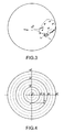
- the calculating unit 9 calculates the vertical displacement angle ⁇ and horizontal displacement angle ⁇ of the representative point A with respect to the optical axis O on the image.
- a coordinate system for indicating displacement angles with respect to the optical axis O on the image is set in the calculating unit 9, and the calculating unit 9 calculates the vertical displacement angle ⁇ and horizontal displacement angle ⁇ of the representative point A on the basis of the coordinate system.
- the calculating unit 9 calculates a distance D1 to the representative point A along the optical axis O, and a distance D2 from the representative point A to the optical axis O along a perpendicular from the representative point A to the optical axis O.
- the distance D1 is expressed by Expression (1) on an assumption that the surface of the road on which the representative point A is located and a contact surface with which the host vehicle is in contact are included in the same plane.
- D 1 H ⁇ tan(90 - ⁇ )
- D2 D 1 ⁇ tan ⁇
- the displacement angle ⁇ 2 of a boundary between the body 1 and the surface of the road may be measured and may be used as reference information about the displacement angle ⁇ .
- the displacement angle ⁇ 2 is dependent on the positions of the cameras 5 and 6, and the morphology of the body 1. If the positions of the cameras 5 and 6 include an error, the displacement angle ⁇ 2 changes. Therefore, the accuracy of detection of the position of the moving object relative to that of the host vehicle can be improved by correcting the displacement angle ⁇ according to an error in the displacement angle ⁇ 2.
- the calculating unit 9 generates an output signal to be given to the display 10 on the basis of information about the respective positions of the moving objects relative to the position of the host vehicle. For example, a triangle representing the host vehicle is displayed in a central part of the screen of the display 10, and rectangles representing the moving objects, such as vehicles traveling alongside the host vehicle and oncoming vehicles, are displayed on the screen of the display 10. The velocities of the moving objects relative to the host vehicle are displayed by vector notation on the screen of the display 10. When the distance between the host vehicle and the moving object decreases below a predetermined threshold, a warning may be given to that effect by, for example, flickering the rectangle representing the moving object.
- the vehicle surroundings monitoring apparatus 2 since the vehicle surroundings monitoring apparatus 2 in this embodiment obtains images of objects around the host vehicle by the cameras 5 and 6 having the imaging lens systems 5a and 6a provided with fish-eye lenses, respectively, the vehicle surroundings monitoring apparatus 2 is capable of Obtaining images of a wide range by using a small number of image obtaining devices.
- the vehicle surroundings monitoring apparatus 2 is readily able to detect moving objects, such as vehicles traveling alongside the host vehicle, and oncoming vehicles, by producing an optical flow between two images successively obtained at different times, respectively.
- the position of a moving object relative to the host vehicle can be readily calculated on the basis of the displacement angle from the optical axis O by setting the representative point A representing the detected moving object on the surface of the road. That is, the cameras 5 and 6 are set on the host vehicle with their optical axes O extended in a horizontal plane, and the distance between the host vehicle and the representative point A can be readily calculated on the basis of the displacement angle from the optical axis O on an assumption that the representative point A is in a plane including the surface with which the host vehicle is in contact. Therefore, any stereoscopic image processing operation and the like are unnecessary, the positional relation between the host vehicle and the moving object can be recognized from an image obtained by the single camera 5 or 6.
- the vehicle surroundings monitoring apparatus of a simple configuration proper information about the ambience of the host vehicle can be obtained by the vehicle surroundings monitoring apparatus of a simple configuration.
- the surroundings of the host vehicle can be effectively monitored by a small number of imaging devices by disposing the cameras 5 and 6 on the right and the left side of the body 1, respectively.
- Images of regions which are difficult for the driver to monitor can be effectively obtained by disposing the cameras 5 and 6 with their optical axes O inclined slightly rearward to a direction parallel to the width of the host vehicle.
- Indication of the velocities of the moving objects relative to the host vehicle by vector notation on the display 10 is effective in making the driver recognize vehicles traveling alongside the host vehicle, and oncoming vehicles.
- the vehicle surroundings monitoring apparatus 2 in the foregoing embodiment is provided with the cameras 5 and 6 disposed at the right and the left part of the body 1
- the vehicle surroundings monitoring apparatus may be provided with cameras 15 and 16 disposed at right and left parts of the body 1, respectively, and a camera 17 disposed at a rear part of the body 1 as shown in Fig. 8.
- the vehicle surroundings monitoring apparatus is provided with the cameras 15, 16 and 17, it is desirable to dispose the cameras 15 and 16 on the body 1 with their optical axes O extended in a middle part of the body 1 in parallel to the width of the body 1.
- the vehicle surroundings monitoring apparatus is simple in construction and is capable of acquiring information about the surroundings of the vehicle by using a small number of image obtaining means.
Abstract
Description
- The present invention relates to a vehicle surroundings monitoring apparatus for a vehicle, capable of detecting moving objects, such as vehicles traveling around a vehicle provided with the vehicle surroundings monitoring apparatus (hereinafter, referred to as "host vehicle"), on the basis of images provided by a fish-eye lens.
- Various types of vehicle surroundings monitoring apparatuses have been proposed and applied to practical uses in recent years for the improvement of safety of vehicles. Those vehicle surroundings monitoring apparatuses are capable of three-dimensionally recognizing roads and traffic conditions in a practically satisfactory accuracy and in a practically permissible time by obtaining images of scenery extending ahead of the host vehicle or objects lying in front of the host vehicle by a camera and processing the images.
- A technique proposed in, for example, JP-A No. 283461/1998 by the applicant of the present patent application subjects images taken by a pair of cameras (stereo camera) to a stereoscopic process to detect the preceding vehicle and obstacles.
- It is desirable, for the further improvement of the safety of the host vehicle, to give information about other vehicles and the like traveling beside the host vehicle to the driver in addition to that about a space in front of the host vehicle. Preferably, an image of scenery extending around the side of the host vehicle is obtained by a camera provided with a fish-eye lens to acquire information about a wide range of the side scenery. For example, a technique disclosed in JP-A No. 202180/1997 obtains an image of the side scenery by a fish-eye lens camera, converts the image into a regular image signal by a coordinate transformation circuit, and displays an optional region of a rectified image on the screen of a monitor. However, since this technique merely displays the image of a predetermined part of the vehicle's surroundings on the screen of the monitor, it is difficult to give the driver distance information representing distances between the host vehicle and other vehicles traveling beside the host vehicle.
- To deal with such a difficulty in giving the driver distance information, a technique disclosed in, for example, JP-B No. 2611173 uses a monitoring system including a plurality of cameras respectively provided with fish-eye lenses. The monitoring system calculates three-dimensional coordinates indicating the three-dimensional position of a moving object on the basis of a plurality of wide-angle images provided by the plurality of cameras to acquire distance information about the distance between the host vehicle and a vehicle traveling beside the host vehicle. However, it is not economically preferable to use such a monitoring system of complicated construction for obtaining information about a side space extending around the side of the host vehicle, which may be rough as compared with information about a forward space extending in front of the host vehicle.
- The present invention has been made in view of such circumstances, and it is therefore an object of the present invention to provide a vehicle surroundings monitoring apparatus of simple construction capable of obtaining proper information about the surroundings of a host vehicle.
- According to one aspect of the present invention, a vehicle surroundings monitoring apparatus for monitoring the surroundings of a host vehicle includes: image obtaining means each having an imaging lens system including a fish-eye lens; an image processing means capable of detecting a moving object on the basis of an optical flow between two images obtained by the image obtaining means respectively at different times, by using one of the images as a reference image, and of setting a representative point representing the moving object on the surface of a road; and a calculating means for calculating the position of the moving object relative to the vehicle on the basis of a displacement angle of the representative point from the optical axis on an image.
- In the vehicle surroundings monitoring apparatus according to the present invention, the image obtaining means are disposed on right and left side parts of a body included in the host vehicle.
- In the vehicle surroundings monitoring apparatus according to the present invention, the imaging lens system has an optical axis inclined slightly rearward to a direction parallel to the width of the vehicle.
- In the vehicle surroundings monitoring apparatus according to the present invention may further include a display means for displaying the positions of moving objects relative to the host vehicle, capable of indicating the velocities of the moving objects relative to the host vehicle by vector notation.
- By way of example only, specific embodiments of the present invention will now be described, with reference to the accompanying drawings, in which:
- Fig. 1 is a functional block diagram of a vehicle surroundings monitoring apparatus in a preferred embodiment according to the present invention;
- Fig. 2 is a diagrammatic view for explaining image regions obtained by a image obtaining means in an example;
- Fig. 3 is a simplified diagram showing a distribution of velocity vectors;
- Fig. 4 is a diagram showing a coordinate system for indicating angle of displacement from an optical axis;
- Fig. 5 is a diagrammatic view for explaining the positional relation between a vehicle and a representative point;
- Fig. 6 is a diagrammatic view of for explaining a method of calculating the distance between a vehicle and a representative point with respect to a direction parallel to an optical axis;
- Fig. 7 is a diagrammatic view showing an image displayed on the screen of a display; and
- Fig. 8 is a diagrammatic view for explaining image regions obtained by a image obtaining means in another example.
-
- Referring to Fig. 1, a vehicle provided with a vehicle
surroundings monitoring apparatus 2 in a preferred embodiment according to the present invention, i.e. a host vehicle, has abody 1. The vehiclesurroundings monitoring apparatus 2 obtains images of outside sceneries in set ranges, recognizes outside moving objects, such as vehicles traveling alongside the host vehicle and oncoming vehicles, and monitors the outside moving objects. The vehiclesurroundings monitoring apparatus 2 comprises cameras (image obtaining means) 5 and 6 disposed on the right and the left side of thebody 1 respectively, image processing units (image processing means) 7 and 8 capable of processing images obtained by thecameras - The
cameras imaging lens systems imaging lens systems cameras cameras body 1 at a height H, respectively, such that the optical axes O of theimaging lens systems body 1 in a horizontal plane. As shown in Fig. 2, the respective angular ranges of thecameras body 1 and behind thebody 1. In this embodiment, the vehicle is supposed to be a wagon and thebody 1 is of a wagon type. Desirably, the cameras are attached to the D-pillars of thebody 1. - The
cameras image processing units image processing units image processing units speed sensor 11 for measuring the traveling speed of the host vehicle and asteering angle sensor 12 for measuring steering angles. Each of theimage processing units cameras image processing units - As shown in Fig. 3, velocity vectors representing the velocities of fixed objects, such as the surface of a road, have a direction substantially opposite to the traveling direction of the host vehicle and a magnitude substantially equal to the traveling velocity of the host vehicle. In contrast, velocity vectors representing the velocities of moving objects, such as vehicles traveling alongside the host vehicle, and oncoming vehicles, have magnitudes different from that of a velocity vector representing the traveling speed of the host vehicle. The
image processing units - The
image processing units image processing units image processing units - The
image processing units unit 9 to give information about the representative point A of each of moving objects on the image. The calculatingunit 9 calculates the vertical displacement angle α and horizontal displacement angle β of the representative point A with respect to the optical axis O on the image. A coordinate system for indicating displacement angles with respect to the optical axis O on the image is set in the calculatingunit 9, and the calculatingunit 9 calculates the vertical displacement angle α and horizontal displacement angle β of the representative point A on the basis of the coordinate system. Then, the calculatingunit 9 calculates a distance D1 to the representative point A along the optical axis O, and a distance D2 from the representative point A to the optical axis O along a perpendicular from the representative point A to the optical axis O. - Since the optical axis O extends in a horizontal plane at a height H from the surface of the road as shown in Fig. 6, the distance D1 is expressed by Expression (1) on an assumption that the surface of the road on which the representative point A is located and a contact surface with which the host vehicle is in contact are included in the same plane.
D - D2 is expressed by Expression (2).
D D - If a part of the
body 1 is included in the field of view of theimaging lens systems body 1 and the surface of the road may be measured and may be used as reference information about the displacement angle α. The displacement angle α2 is dependent on the positions of thecameras body 1. If the positions of thecameras - The calculating
unit 9 generates an output signal to be given to thedisplay 10 on the basis of information about the respective positions of the moving objects relative to the position of the host vehicle. For example, a triangle representing the host vehicle is displayed in a central part of the screen of thedisplay 10, and rectangles representing the moving objects, such as vehicles traveling alongside the host vehicle and oncoming vehicles, are displayed on the screen of thedisplay 10. The velocities of the moving objects relative to the host vehicle are displayed by vector notation on the screen of thedisplay 10. When the distance between the host vehicle and the moving object decreases below a predetermined threshold, a warning may be given to that effect by, for example, flickering the rectangle representing the moving object. - Since the vehicle
surroundings monitoring apparatus 2 in this embodiment obtains images of objects around the host vehicle by thecameras imaging lens systems surroundings monitoring apparatus 2 is capable of Obtaining images of a wide range by using a small number of image obtaining devices. - The vehicle
surroundings monitoring apparatus 2 is readily able to detect moving objects, such as vehicles traveling alongside the host vehicle, and oncoming vehicles, by producing an optical flow between two images successively obtained at different times, respectively. - The position of a moving object relative to the host vehicle can be readily calculated on the basis of the displacement angle from the optical axis O by setting the representative point A representing the detected moving object on the surface of the road. That is, the
cameras single camera cameras body 1, respectively. - Images of regions which are difficult for the driver to monitor can be effectively obtained by disposing the
cameras - Indication of the velocities of the moving objects relative to the host vehicle by vector notation on the
display 10 is effective in making the driver recognize vehicles traveling alongside the host vehicle, and oncoming vehicles. - Although the vehicle
surroundings monitoring apparatus 2 in the foregoing embodiment is provided with thecameras body 1, the vehicle surroundings monitoring apparatus may be provided withcameras body 1, respectively, and acamera 17 disposed at a rear part of thebody 1 as shown in Fig. 8. When the vehicle surroundings monitoring apparatus is provided with thecameras cameras body 1 with their optical axes O extended in a middle part of thebody 1 in parallel to the width of thebody 1. - As apparent from the foregoing description, according to the present invention, the vehicle surroundings monitoring apparatus is simple in construction and is capable of acquiring information about the surroundings of the vehicle by using a small number of image obtaining means.
- Although the invention has been described in its preferred embodiment with a certain degree of particularity, obviously many changes and variations are possible therein. It is therefore to be understood that the present invention may be practiced otherwise than as specifically described herein without departing from the scope thereof.
Claims (5)
- A vehicle surroundings monitoring apparatus comprising:image obtaining means each having an imaging lens system including a fish-eye lens;an image processing means capable of detecting a moving object on the basis of an optical flow between two images obtained by the image obtaining means respectively at different times, using one of the images as a reference image, and of setting a representative point representing the moving object on a surface of a road; anda calculating means for calculating the position of the moving object relative to the vehicle on the basis of a displacement angle of the representative point from the optical axis on an image.
- The vehicle surroundings monitoring apparatus according to claim 1, wherein the image obtaining means are disposed on right and left side parts of a body included in a host vehicle, respectively.
- The vehicle surroundings monitoring apparatus according to claim 2, wherein each imaging lens system has an optical axis inclined slightly rearward to a direction parallel to the width of the host vehicle.
- The vehicle surroundings monitoring apparatus according to any one of claims 1 to 3 further comprising a display means for displaying positions of moving objects relative to that of the host vehicle, capable of indicating velocities of the moving objects relative to the host vehicle by vector notation.
- A vehicle comprising the vehicle surroundings monitoring apparatus as claimed in any of claims 1 to 4.
Applications Claiming Priority (2)
| Application Number | Priority Date | Filing Date | Title |
|---|---|---|---|
| JP2001174620 | 2001-06-08 | ||
| JP2001174620A JP4425495B2 (en) | 2001-06-08 | 2001-06-08 | Outside monitoring device |
Publications (3)
| Publication Number | Publication Date |
|---|---|
| EP1264734A2 true EP1264734A2 (en) | 2002-12-11 |
| EP1264734A3 EP1264734A3 (en) | 2004-09-15 |
| EP1264734B1 EP1264734B1 (en) | 2006-11-02 |
Family
ID=19015880
Family Applications (1)
| Application Number | Title | Priority Date | Filing Date |
|---|---|---|---|
| EP02253992A Expired - Fee Related EP1264734B1 (en) | 2001-06-08 | 2002-06-07 | Vehicle surroundings monitoring apparatus |
Country Status (4)
| Country | Link |
|---|---|
| US (1) | US6812831B2 (en) |
| EP (1) | EP1264734B1 (en) |
| JP (1) | JP4425495B2 (en) |
| DE (1) | DE60215718T2 (en) |
Cited By (11)
| Publication number | Priority date | Publication date | Assignee | Title |
|---|---|---|---|---|
| WO2004068440A1 (en) | 2003-01-27 | 2004-08-12 | Daimlerchrysler Ag | Vehicle comprising a catadioptric camera |
| DE10313002A1 (en) * | 2003-03-24 | 2004-10-21 | Daimlerchrysler Ag | Video image display for a vehicle environment detection unit |
| EP1547866A1 (en) * | 2003-12-25 | 2005-06-29 | Sharp Kabushiki Kaisha | Surrounding surveillance apparatus and mobile body |
| EP1679529A2 (en) * | 2005-01-04 | 2006-07-12 | Robert Bosch Gmbh | Object detection method |
| EP1480054A3 (en) * | 2003-05-23 | 2006-08-30 | Robert Bosch Gmbh | Cruise control for a vehicle |
| WO2008122498A2 (en) * | 2007-04-10 | 2008-10-16 | Robert Bosch Gmbh | Method for displaying a forward roadway and control device |
| EP2163429A2 (en) | 2008-08-29 | 2010-03-17 | MAN Nutzfahrzeuge AG | Method for image-supported monitoring of a vehicle environment, especially the environment of a goods vehicle |
| EP2272730A1 (en) * | 2009-07-07 | 2011-01-12 | HI-KEY Limited | Method and apparatus for displaying distance data in a parking distance control system |
| GB2472773B (en) * | 2009-08-13 | 2015-01-28 | Light Blue Optics Ltd | Head up displays |
| CN104417454A (en) * | 2013-08-27 | 2015-03-18 | 现代自动车株式会社 | Device and method for detecting obstacles |
| US10666908B2 (en) | 2012-12-18 | 2020-05-26 | Hyundai Autron Co., Ltd. | Camera module for vehicle and monitoring system provided with the same |
Families Citing this family (55)
| Publication number | Priority date | Publication date | Assignee | Title |
|---|---|---|---|---|
| US20140152823A1 (en) * | 1998-11-30 | 2014-06-05 | American Vehicular Sciences Llc | Techniques to Obtain Information About Objects Around a Vehicle |
| KR200277875Y1 (en) * | 2002-03-11 | 2002-06-14 | 이스턴 마스텍 주식회사 | Normal/Mirror switching appatatus for back monitoring camera of car |
| DE10235414A1 (en) * | 2002-08-02 | 2004-02-12 | Robert Bosch Gmbh | Method and device for determining the impending inevitable collision |
| JP4244684B2 (en) * | 2003-04-10 | 2009-03-25 | 三菱自動車工業株式会社 | Vehicle monitoring device |
| US7542834B2 (en) * | 2003-10-17 | 2009-06-02 | Panasonic Corporation | Mobile unit motion calculating method, apparatus and navigation system |
| JP2005223524A (en) * | 2004-02-04 | 2005-08-18 | Nissan Motor Co Ltd | Supervisory apparatus for surrounding of vehicle |
| DE102005013920B4 (en) * | 2004-03-26 | 2007-12-13 | Mitsubishi Jidosha Kogyo K.K. | Front view monitoring apparatus |
| US7397496B2 (en) * | 2004-04-15 | 2008-07-08 | Kenneth Eugene Arant | Apparatus system for recovering evidence of extrinsic wrongful acts in vehicular incidents |
| US7679497B1 (en) | 2004-04-15 | 2010-03-16 | Kenneth Eugene Arant | Recovering legal evidence of unfavorable events or conditions during vehicle operations |
| JP4744823B2 (en) * | 2004-08-05 | 2011-08-10 | 株式会社東芝 | Perimeter monitoring apparatus and overhead image display method |
| JP4107605B2 (en) * | 2005-02-01 | 2008-06-25 | シャープ株式会社 | Moving object periphery monitoring device, moving object periphery monitoring method, control program, and readable recording medium |
| JP4657765B2 (en) * | 2005-03-09 | 2011-03-23 | 三菱自動車工業株式会社 | Nose view system |
| JP2006311272A (en) * | 2005-04-28 | 2006-11-09 | Denso Corp | Video display device for vehicle |
| JP2007147458A (en) * | 2005-11-28 | 2007-06-14 | Fujitsu Ltd | Location detector, location detection method, location detection program, and recording medium |
| US20080140306A1 (en) * | 2005-11-30 | 2008-06-12 | Snodgrass Ken L | Voice recognition method and system for displaying charts and maps |
| US20070150138A1 (en) | 2005-12-08 | 2007-06-28 | James Plante | Memory management in event recording systems |
| US10878646B2 (en) | 2005-12-08 | 2020-12-29 | Smartdrive Systems, Inc. | Vehicle event recorder systems |
| US20070132773A1 (en) * | 2005-12-08 | 2007-06-14 | Smartdrive Systems Inc | Multi-stage memory buffer and automatic transfers in vehicle event recording systems |
| US20070135980A1 (en) * | 2005-12-09 | 2007-06-14 | Smartdrive Systems Inc | Vehicle event recorder systems |
| US20070135979A1 (en) * | 2005-12-09 | 2007-06-14 | Smartdrive Systems Inc | Vehicle event recorder systems |
| US8996240B2 (en) | 2006-03-16 | 2015-03-31 | Smartdrive Systems, Inc. | Vehicle event recorders with integrated web server |
| US9201842B2 (en) | 2006-03-16 | 2015-12-01 | Smartdrive Systems, Inc. | Vehicle event recorder systems and networks having integrated cellular wireless communications systems |
| WO2007144843A2 (en) * | 2006-06-16 | 2007-12-21 | Koninklijke Philips Electronics N.V. | Multi-view display devices |
| JP5159070B2 (en) * | 2006-08-31 | 2013-03-06 | アルパイン株式会社 | Vehicle periphery image display device and display method |
| US8989959B2 (en) | 2006-11-07 | 2015-03-24 | Smartdrive Systems, Inc. | Vehicle operator performance history recording, scoring and reporting systems |
| US8649933B2 (en) | 2006-11-07 | 2014-02-11 | Smartdrive Systems Inc. | Power management systems for automotive video event recorders |
| US8868288B2 (en) | 2006-11-09 | 2014-10-21 | Smartdrive Systems, Inc. | Vehicle exception event management systems |
| US8139820B2 (en) | 2006-12-13 | 2012-03-20 | Smartdrive Systems Inc. | Discretization facilities for vehicle event data recorders |
| US8239092B2 (en) * | 2007-05-08 | 2012-08-07 | Smartdrive Systems Inc. | Distributed vehicle event recorder systems having a portable memory data transfer system |
| US8552848B2 (en) * | 2007-08-16 | 2013-10-08 | Ford Global Technologies, Llc | System and method for combined blind spot detection and rear crossing path collision warning |
| EP2431226B1 (en) * | 2010-09-17 | 2016-07-27 | SMR Patents S.à.r.l. | Rear view device for a motor vehicle |
| KR20120053713A (en) * | 2010-11-18 | 2012-05-29 | 에스엘 주식회사 | Apparatus and method for controlling a vehicle camera |
| JP5556748B2 (en) * | 2011-06-21 | 2014-07-23 | 株式会社デンソー | Vehicle state detection device |
| US10594989B2 (en) | 2011-09-16 | 2020-03-17 | SMR Patent S.à.r.l. | Safety mirror with telescoping head and motor vehicle |
| US10638094B2 (en) | 2011-09-16 | 2020-04-28 | SMR PATENTS S.á.r.l. | Side rearview vision assembly with telescoping head |
| US9728228B2 (en) | 2012-08-10 | 2017-08-08 | Smartdrive Systems, Inc. | Vehicle event playback apparatus and methods |
| US9501878B2 (en) | 2013-10-16 | 2016-11-22 | Smartdrive Systems, Inc. | Vehicle event playback apparatus and methods |
| DE102013111840A1 (en) | 2013-10-28 | 2015-04-30 | Dr. Ing. H.C. F. Porsche Aktiengesellschaft | Method for detecting an object |
| US9610955B2 (en) | 2013-11-11 | 2017-04-04 | Smartdrive Systems, Inc. | Vehicle fuel consumption monitor and feedback systems |
| US10210399B2 (en) * | 2013-12-20 | 2019-02-19 | Magna Electronics Inc. | Vehicle vision system with image processing |
| US8892310B1 (en) | 2014-02-21 | 2014-11-18 | Smartdrive Systems, Inc. | System and method to detect execution of driving maneuvers |
| US9663127B2 (en) | 2014-10-28 | 2017-05-30 | Smartdrive Systems, Inc. | Rail vehicle event detection and recording system |
| US11069257B2 (en) | 2014-11-13 | 2021-07-20 | Smartdrive Systems, Inc. | System and method for detecting a vehicle event and generating review criteria |
| JP2016103249A (en) * | 2014-11-28 | 2016-06-02 | 富士通株式会社 | Driving support device and driving support method |
| US9679420B2 (en) | 2015-04-01 | 2017-06-13 | Smartdrive Systems, Inc. | Vehicle event recording system and method |
| JP6623729B2 (en) * | 2015-12-04 | 2019-12-25 | 株式会社ソシオネクスト | Ranging systems, moving objects and parts |
| KR102491637B1 (en) * | 2015-12-10 | 2023-01-26 | 한화테크윈 주식회사 | Apparatus for Providing Image and Method Thereof |
| US9786104B2 (en) | 2016-01-25 | 2017-10-10 | Smartdrive Systems, Inc. | Systems and method to trigger vehicle events based on contextual information |
| WO2017154317A1 (en) * | 2016-03-09 | 2017-09-14 | 株式会社Jvcケンウッド | Vehicle display control device, vehicle display system, vehicle display control method, and program |
| US10818109B2 (en) | 2016-05-11 | 2020-10-27 | Smartdrive Systems, Inc. | Systems and methods for capturing and offloading different information based on event trigger type |
| EP3364336B1 (en) * | 2017-02-20 | 2023-12-20 | Continental Autonomous Mobility Germany GmbH | A method and apparatus for estimating a range of a moving object |
| WO2019043877A1 (en) * | 2017-08-31 | 2019-03-07 | 株式会社オプティム | Image analysis distance information provision system, image analysis distance information provision method, and program |
| WO2019043879A1 (en) * | 2017-08-31 | 2019-03-07 | 株式会社オプティム | Image analysis distance information provision system, image analysis distance information provision method, and program |
| EP3954580A1 (en) * | 2018-06-13 | 2022-02-16 | Ride Vision Ltd. | A rider assistance system and method |
| JP7353821B2 (en) * | 2019-06-24 | 2023-10-02 | キヤノン株式会社 | Image processing device, its control method, program |
Citations (2)
| Publication number | Priority date | Publication date | Assignee | Title |
|---|---|---|---|---|
| JPH09202180A (en) | 1996-01-29 | 1997-08-05 | Niles Parts Co Ltd | On-board camera device |
| JPH10283461A (en) | 1997-04-04 | 1998-10-23 | Fuji Heavy Ind Ltd | Outer-vehicle monitoring device |
Family Cites Families (9)
| Publication number | Priority date | Publication date | Assignee | Title |
|---|---|---|---|---|
| US4872051A (en) * | 1987-10-01 | 1989-10-03 | Environmental Research Institute Of Michigan | Collision avoidance alarm system |
| JP2611173B2 (en) | 1992-06-11 | 1997-05-21 | 運輸省船舶技術研究所長 | Positioning method and device using fisheye lens |
| US5680123A (en) * | 1996-08-06 | 1997-10-21 | Lee; Gul Nam | Vehicle monitoring system |
| US5978017A (en) * | 1997-04-08 | 1999-11-02 | Tino; Jerald N. | Multi-camera video recording system for vehicles |
| JPH11353565A (en) * | 1998-06-09 | 1999-12-24 | Yazaki Corp | Method and device for alarm of collision for vehicle |
| US6201642B1 (en) * | 1999-07-27 | 2001-03-13 | Donnelly Corporation | Vehicular vision system with a wide angle lens including a diffractive element |
| JP2000225970A (en) * | 1998-11-30 | 2000-08-15 | Tuner Kk | Image recording system loaded on vehicle |
| JP4287532B2 (en) * | 1999-03-01 | 2009-07-01 | 矢崎総業株式会社 | Vehicle rear side monitoring device |
| US6424272B1 (en) * | 2001-03-30 | 2002-07-23 | Koninklijke Philips Electronics, N.V. | Vehicular blind spot vision system |
-
2001
- 2001-06-08 JP JP2001174620A patent/JP4425495B2/en not_active Expired - Fee Related
-
2002
- 2002-06-06 US US10/162,570 patent/US6812831B2/en not_active Expired - Fee Related
- 2002-06-07 DE DE60215718T patent/DE60215718T2/en not_active Expired - Lifetime
- 2002-06-07 EP EP02253992A patent/EP1264734B1/en not_active Expired - Fee Related
Patent Citations (2)
| Publication number | Priority date | Publication date | Assignee | Title |
|---|---|---|---|---|
| JPH09202180A (en) | 1996-01-29 | 1997-08-05 | Niles Parts Co Ltd | On-board camera device |
| JPH10283461A (en) | 1997-04-04 | 1998-10-23 | Fuji Heavy Ind Ltd | Outer-vehicle monitoring device |
Cited By (17)
| Publication number | Priority date | Publication date | Assignee | Title |
|---|---|---|---|---|
| WO2004068440A1 (en) | 2003-01-27 | 2004-08-12 | Daimlerchrysler Ag | Vehicle comprising a catadioptric camera |
| DE10313002A1 (en) * | 2003-03-24 | 2004-10-21 | Daimlerchrysler Ag | Video image display for a vehicle environment detection unit |
| DE10313002B4 (en) * | 2003-03-24 | 2006-03-23 | Daimlerchrysler Ag | Vehicle environment detection unit |
| EP1480054A3 (en) * | 2003-05-23 | 2006-08-30 | Robert Bosch Gmbh | Cruise control for a vehicle |
| EP1547866A1 (en) * | 2003-12-25 | 2005-06-29 | Sharp Kabushiki Kaisha | Surrounding surveillance apparatus and mobile body |
| US7190259B2 (en) | 2003-12-25 | 2007-03-13 | Sharp Kabushiki Kaisha | Surrounding surveillance apparatus and mobile body |
| EP1679529A2 (en) * | 2005-01-04 | 2006-07-12 | Robert Bosch Gmbh | Object detection method |
| EP1679529A3 (en) * | 2005-01-04 | 2006-09-20 | Robert Bosch Gmbh | Object detection method |
| WO2008122498A2 (en) * | 2007-04-10 | 2008-10-16 | Robert Bosch Gmbh | Method for displaying a forward roadway and control device |
| WO2008122498A3 (en) * | 2007-04-10 | 2009-07-16 | Bosch Gmbh Robert | Method for displaying a forward roadway and control device |
| EP2163429A2 (en) | 2008-08-29 | 2010-03-17 | MAN Nutzfahrzeuge AG | Method for image-supported monitoring of a vehicle environment, especially the environment of a goods vehicle |
| EP2163429A3 (en) * | 2008-08-29 | 2011-03-02 | MAN Nutzfahrzeuge AG | Method for image-supported monitoring of a vehicle environment, especially the environment of a goods vehicle |
| EP2272730A1 (en) * | 2009-07-07 | 2011-01-12 | HI-KEY Limited | Method and apparatus for displaying distance data in a parking distance control system |
| GB2472773B (en) * | 2009-08-13 | 2015-01-28 | Light Blue Optics Ltd | Head up displays |
| US10666908B2 (en) | 2012-12-18 | 2020-05-26 | Hyundai Autron Co., Ltd. | Camera module for vehicle and monitoring system provided with the same |
| CN104417454A (en) * | 2013-08-27 | 2015-03-18 | 现代自动车株式会社 | Device and method for detecting obstacles |
| CN104417454B (en) * | 2013-08-27 | 2018-05-15 | 现代自动车株式会社 | Apparatus and method for detecting barrier |
Also Published As
| Publication number | Publication date |
|---|---|
| JP4425495B2 (en) | 2010-03-03 |
| DE60215718D1 (en) | 2006-12-14 |
| EP1264734B1 (en) | 2006-11-02 |
| DE60215718T2 (en) | 2007-08-30 |
| US20020186298A1 (en) | 2002-12-12 |
| EP1264734A3 (en) | 2004-09-15 |
| JP2002366937A (en) | 2002-12-20 |
| US6812831B2 (en) | 2004-11-02 |
Similar Documents
| Publication | Publication Date | Title |
|---|---|---|
| US6812831B2 (en) | Vehicle surroundings monitoring apparatus | |
| US11836989B2 (en) | Vehicular vision system that determines distance to an object | |
| EP2071491B1 (en) | Stereo camera device | |
| US11610410B2 (en) | Vehicular vision system with object detection | |
| US10183621B2 (en) | Vehicular image processing apparatus and vehicular image processing system | |
| US7576639B2 (en) | Systems and methods for detecting pedestrians in the vicinity of a powered industrial vehicle | |
| EP1005234B1 (en) | Three-dimensional scope system for vehicles with a single camera | |
| KR100466458B1 (en) | Device for assisting automobile driver | |
| US7652686B2 (en) | Device for image detecting objects, people or similar in the area surrounding a vehicle | |
| EP1251032A2 (en) | Apparatus and method of recognizing vehicle travelling behind | |
| JP2018537329A (en) | Method and apparatus for determining a covered area in a vehicle periphery of a vehicle | |
| JP2021510227A (en) | Multispectral system for providing pre-collision alerts | |
| JP4948338B2 (en) | Inter-vehicle distance measuring device | |
| JP3961584B2 (en) | Lane marking detector | |
| JP4848644B2 (en) | Obstacle recognition system | |
| JP3586938B2 (en) | In-vehicle distance measuring device | |
| JP3612821B2 (en) | In-vehicle distance measuring device | |
| US20230150499A1 (en) | Vehicle control system and vehicle driving method using the vehicle control system | |
| JP5723561B2 (en) | Driving assistance device | |
| JPH1141521A (en) | Image pickup device, instrument and method for measuring distance between vehicles | |
| CN115943287A (en) | Vehicle attitude estimation system and vehicle attitude estimation method | |
| US11924578B2 (en) | Image processing apparatus, camera, moveable body, and image processing method | |
| US20230154196A1 (en) | Vehicle control system and vehicle driving method using the vehicle control system | |
| US20230150533A1 (en) | Vehicle control system and vehicle driving method using the vehicle control system | |
| US20230150515A1 (en) | Vehicle control system and vehicle driving method using the vehicle control system |
Legal Events
| Date | Code | Title | Description |
|---|---|---|---|
| PUAI | Public reference made under article 153(3) epc to a published international application that has entered the european phase |
Free format text: ORIGINAL CODE: 0009012 |
|
| AK | Designated contracting states |
Kind code of ref document: A2 Designated state(s): AT BE CH CY DE DK ES FI FR GB GR IE IT LI LU MC NL PT SE TR |
|
| AX | Request for extension of the european patent |
Free format text: AL;LT;LV;MK;RO;SI |
|
| PUAL | Search report despatched |
Free format text: ORIGINAL CODE: 0009013 |
|
| AK | Designated contracting states |
Kind code of ref document: A3 Designated state(s): AT BE CH CY DE DK ES FI FR GB GR IE IT LI LU MC NL PT SE TR |
|
| AX | Request for extension of the european patent |
Extension state: AL LT LV MK RO SI |
|
| RIC1 | Information provided on ipc code assigned before grant |
Ipc: 7G 08G 1/16 B Ipc: 7B 60R 1/00 A |
|
| 17P | Request for examination filed |
Effective date: 20050225 |
|
| AKX | Designation fees paid |
Designated state(s): AT BE |
|
| RBV | Designated contracting states (corrected) |
Designated state(s): DE GB |
|
| 17Q | First examination report despatched |
Effective date: 20050519 |
|
| REG | Reference to a national code |
Ref country code: DE Ref legal event code: 8566 |
|
| GRAP | Despatch of communication of intention to grant a patent |
Free format text: ORIGINAL CODE: EPIDOSNIGR1 |
|
| GRAS | Grant fee paid |
Free format text: ORIGINAL CODE: EPIDOSNIGR3 |
|
| GRAA | (expected) grant |
Free format text: ORIGINAL CODE: 0009210 |
|
| AK | Designated contracting states |
Kind code of ref document: B1 Designated state(s): DE GB |
|
| REG | Reference to a national code |
Ref country code: GB Ref legal event code: FG4D |
|
| REF | Corresponds to: |
Ref document number: 60215718 Country of ref document: DE Date of ref document: 20061214 Kind code of ref document: P |
|
| PLBE | No opposition filed within time limit |
Free format text: ORIGINAL CODE: 0009261 |
|
| STAA | Information on the status of an ep patent application or granted ep patent |
Free format text: STATUS: NO OPPOSITION FILED WITHIN TIME LIMIT |
|
| 26N | No opposition filed |
Effective date: 20070803 |
|
| GBPC | Gb: european patent ceased through non-payment of renewal fee |
Effective date: 20070607 |
|
| PG25 | Lapsed in a contracting state [announced via postgrant information from national office to epo] |
Ref country code: GB Free format text: LAPSE BECAUSE OF NON-PAYMENT OF DUE FEES Effective date: 20070607 |
|
| REG | Reference to a national code |
Ref country code: DE Ref legal event code: R082 Ref document number: 60215718 Country of ref document: DE Representative=s name: VOSSIUS & PARTNER PATENTANWAELTE RECHTSANWAELT, DE Ref country code: DE Ref legal event code: R081 Ref document number: 60215718 Country of ref document: DE Owner name: SUBARU CORPORATION, JP Free format text: FORMER OWNER: FUJI JUKOGYO K.K., TOKIO/TOKYO, JP |
|
| PGFP | Annual fee paid to national office [announced via postgrant information from national office to epo] |
Ref country code: DE Payment date: 20170530 Year of fee payment: 16 |
|
| REG | Reference to a national code |
Ref country code: DE Ref legal event code: R119 Ref document number: 60215718 Country of ref document: DE |
|
| PG25 | Lapsed in a contracting state [announced via postgrant information from national office to epo] |
Ref country code: DE Free format text: LAPSE BECAUSE OF NON-PAYMENT OF DUE FEES Effective date: 20190101 |