EP1264566A2 - Blumentopfhalter für die Freilandpflanzenzucht - Google Patents
Blumentopfhalter für die Freilandpflanzenzucht Download PDFInfo
- Publication number
- EP1264566A2 EP1264566A2 EP02076936A EP02076936A EP1264566A2 EP 1264566 A2 EP1264566 A2 EP 1264566A2 EP 02076936 A EP02076936 A EP 02076936A EP 02076936 A EP02076936 A EP 02076936A EP 1264566 A2 EP1264566 A2 EP 1264566A2
- Authority
- EP
- European Patent Office
- Prior art keywords
- pot
- elements
- holder according
- uprights
- holder
- Prior art date
- Legal status (The legal status is an assumption and is not a legal conclusion. Google has not performed a legal analysis and makes no representation as to the accuracy of the status listed.)
- Withdrawn
Links
Images


Classifications
-
- A—HUMAN NECESSITIES
- A47—FURNITURE; DOMESTIC ARTICLES OR APPLIANCES; COFFEE MILLS; SPICE MILLS; SUCTION CLEANERS IN GENERAL
- A47G—HOUSEHOLD OR TABLE EQUIPMENT
- A47G7/00—Flower holders or the like
- A47G7/02—Devices for supporting flower-pots or cut flowers
- A47G7/025—Flower-pot stabilisers, i.e. means to prevent flower-pots from tipping over
Definitions
- the present invention relates to a universal pot-holder for open-air cultivation and its auxiliary elements.
- Pots situated outside the nursery in the open air must be firmly arranged, at the right distance, and the excess rainwater which tends to collect, must be drained.
- perforated trays for example thermoformed, are used, and the pots are inserted in the holes. This again is not an optimum solution as the cultivated area can undergo deterioration due to stagnant water or to geometrical and/or dimensional restrictions caused by the trays themselves.
- the setting up of each are, moreover, is normally determined by the species of plant cultivated in the particular type of pot with a certain equidistance between the pots; at each turnover, however, the new pots are re-divided in the specific lot assigned with an analogous procedure, as in the case of a new cultivation scheme, to reselect the reciprocal distances between each pot and those adjacent.
- a general objective of the present invention is therefore to produce a universal pot-holder which solves the technical problems specified above, in a simple and practical way.
- Another objective of the present invention is to produce a pot-holder which can be placed in a cultivation plant in the open air, rapidly and with firm stability.
- a further objective of the present invention is to produce a pot-holder equipped with elements which can be easily and rapidly connected to other pot-holders in an open-air cultivation, ensuring rapid adjustment to other pot sizes and which can also be repositioned according to measurements established in relation to the type of cultivation.
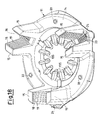
- FIGS. 1-8 illustrate a pot-holder 11 according to the invention, equipped with a spacer element 12 of the interaxis between the pots, not shown, and an anchoring wedge 13, whose position can be regulated for blocking each pot in the respective pot-holder 11.
- the pot-holder 11 has a modular structure, for example, hexagonal, and is produced as a module consisting of a base 14, for example annular and flattened at the bottom, from which a series of uprights 15 extend upwards.
- the uprights 15 are, for example, in the form of three radial couples, whereby each couple identifies a U-shaped seat 16 facing upwards.
- Said seat 16 is suitable for receiving both an arm portion 17 of a spacer element 12 and an anchoring wedge 13, after the positioning of the spacer element 12 (figures 2, 3 and 4, 5).
- the seat 16 On two facing surfaces 18 of the two uprights 15, the seat 16 has a series of reliefs 19 suitable for identifying fitting elements by means of a toothed surface.
- Complementary fitting elements identified by means of complementary toothed grooves 20 situated on opposite lateral surfaces 21 and oriented towards the outside of each arm portion 17 of the spacer element 12, are applied in these reliefs 19, or in the relative fitting elements of the relative surface 18.
- the bottom of the seat 16 also has a series of openings 22 identified by various transversal rods 23 and at one end facing outwards, there is also an extension facing upwards 24 suitable for being inserted in an internal outlet (25) for lightening each arm portion 17 of the star-shaped spacer element 12.
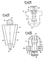
- Said wedge 13 comprises a monolithic body consisting of an upper gripping element 26, lateral surfaces 27, an internal radial supporting surface 29 and a linking element 30.
- the two lateral surfaces 27 are equipped with a series of reliefs 28 complementary to the reliefs 19 of the two facing surfaces 18 of the two uprights 15, thus identifying further fitting elements with the pot-holder 11 and between the various parts.
- stable positioning elements (19, 28) are thus formed in a radial direction between the uprights 15 and the wedges 13.
- the internal radial surface 29 creates a tangential supporting zone for a pot (not shown), when placed inside the pot-holder 11 equipped with three respective spacer elements 12 and three anchoring wedges 13, suitably regulated.
- each anchoring wedge 13 extends laterally in a linking element 30 consisting of an appendage, of which a portion of the lower end forms a hook 31, which is inserted in an opening 22 situated on the bottom of the seat 16, passing through the internal outlet 25 of the arm portion 17 of the star-shaped spacer element 12, and is hooked onto a transversal rod 23.
- a linking element 30 consisting of an appendage, of which a portion of the lower end forms a hook 31, which is inserted in an opening 22 situated on the bottom of the seat 16, passing through the internal outlet 25 of the arm portion 17 of the star-shaped spacer element 12, and is hooked onto a transversal rod 23.
- the appendage 30, forming the linking element is constrained in 36 to the wedge body 13, and is connected to the gripping element 26 by means of an S-shaped extension 32 which creates a certain elasticity between the parts, improving their coupling.
- the internal supporting surface 29, moreover, is connected from below to the wedge body by means of a pliable curved zone 37 which makes the insertion of the pot more adaptable.
- the annular base 14 of the pot-holder 11 can also comprise holes 33 for possible further anchorage to the ground.
- radial spokes 34 can be added together with a central lifting element of the pot 35.
- Both the facing surfaces 18 of the seats 16 between the two uprights 15, the lateral surfaces 21 of each arm portion 17 and also the lateral surfaces 27 of the wedges 13 are slightly and complementarily reamed to allow a better and more stable connection with each other.
- the star-shaped spacer element 12 is available in various lengths, making it possible to cover a wide variety of interaxes between the pot-holders 11 (see figures 16 and 17).
- All the parts can be made of thermoplastic material, also of the recycled type, and can be easily and economically produced by means of moulding.
- the end article according to the present invention has been studied so as to ensure that the pot-holder 11 has a stable positioning also in the presence of strong winds and allows a wide range of pots to be inserted.
- the structure moreover, is such as to easily and safely remove rainwater from the bottom of the pot, which can even, in one of the versions, keep the pot raised above the ground.
- the star-shaped spacer element 12 is available, as already mentioned, in various lengths and has been studied for allowing a correction distribution of even equidistances in the whole cultivation plant set-up. For each specific plant set-up, in fact, it can cover a wide range of interaxes between the pots.
- This spacer element 13 allows the modules 11 to be fixed to each other forming a cell-like structure capable of resisting stress caused by wind, at times strong, which may blow against the pots.
- the anchoring wedge 13 is firstly aimed at holding the pot in position preventing it from being overturned, in spite of the pot-holder.
- This wedge moreover, remains permanently in the seat by means of the hook 31 which passes through the star-shaped spacer element 12 and is firmly anchored to the pot-holder module 11. Finally, it is designed so as to withhold the star-shaped spacer element 12 thus ensuring the housing of the whole structure in the seat.
- All the elements 11, 12 and 13 can be suitably scaled with appropriate indexes and references allowing an easier setting up.
Landscapes
- Cultivation Receptacles Or Flower-Pots, Or Pots For Seedlings (AREA)
Applications Claiming Priority (2)
| Application Number | Priority Date | Filing Date | Title |
|---|---|---|---|
| ITMI20011050 | 2001-05-21 | ||
| IT2001MI001050A ITMI20011050A1 (it) | 2001-05-21 | 2001-05-21 | Portavaso universale per coltivazione in piena aria e suoi elementi ausiliari |
Publications (2)
| Publication Number | Publication Date |
|---|---|
| EP1264566A2 true EP1264566A2 (de) | 2002-12-11 |
| EP1264566A3 EP1264566A3 (de) | 2003-10-08 |
Family
ID=11447703
Family Applications (1)
| Application Number | Title | Priority Date | Filing Date |
|---|---|---|---|
| EP02076936A Withdrawn EP1264566A3 (de) | 2001-05-21 | 2002-05-17 | Blumentopfhalter für die Freilandpflanzenzucht |
Country Status (2)
| Country | Link |
|---|---|
| EP (1) | EP1264566A3 (de) |
| IT (1) | ITMI20011050A1 (de) |
Family Cites Families (5)
| Publication number | Priority date | Publication date | Assignee | Title |
|---|---|---|---|---|
| FR1148341A (fr) * | 1956-05-03 | 1957-12-06 | Perfectionnement aux vases, pots et récipients similaires | |
| DE29601114U1 (de) * | 1996-01-24 | 1996-04-04 | Hausmann, Hermann, 88527 Unlingen | Variabel verstellbarer Pflanztopfhalter |
| US5743508A (en) * | 1996-02-02 | 1998-04-28 | Fiveash; Ramon A. | Tree stand with upward/extending support members forming part of a water basin |
| EP0903993A4 (de) * | 1996-04-24 | 1999-09-22 | Jazzac International Limited | Haltevorrichtung |
| JPH09299209A (ja) * | 1996-05-10 | 1997-11-25 | Norio Sato | 鉢植えの飾り台 |
-
2001
- 2001-05-21 IT IT2001MI001050A patent/ITMI20011050A1/it unknown
-
2002
- 2002-05-17 EP EP02076936A patent/EP1264566A3/de not_active Withdrawn
Also Published As
| Publication number | Publication date |
|---|---|
| EP1264566A3 (de) | 2003-10-08 |
| ITMI20011050A1 (it) | 2002-11-21 |
| ITMI20011050A0 (it) | 2001-05-21 |
Similar Documents
| Publication | Publication Date | Title |
|---|---|---|
| JP4399093B2 (ja) | 蔓性植物の栽培棚の支持構造 | |
| US7140149B2 (en) | High density planter | |
| CN102638968A (zh) | 用于栽培植物的方法和装置 | |
| US6601342B2 (en) | Culture tray for the rooting of young plants | |
| CA1285769C (en) | Connected containers | |
| WO2010083549A1 (en) | Post or wall mounted stackable plant pot | |
| US20160135386A1 (en) | Plant growth support pot | |
| CA2158720C (en) | Modular drainage system for containers | |
| KR200432507Y1 (ko) | 작물의 공중재배용 포트 | |
| US20020121048A1 (en) | High density planter | |
| KR102184907B1 (ko) | 고설재배용 포트 및 이를 이용한 고설재배 베드 | |
| EP1264566A2 (de) | Blumentopfhalter für die Freilandpflanzenzucht | |
| KR101363362B1 (ko) | 수목 재배용 용기 | |
| KR102095126B1 (ko) | 배수 물받이 설치기능을 갖는 딸기 수경재배를 위한 고설베드용 화분 | |
| KR102322640B1 (ko) | 조립식 화분체 | |
| US20030192239A1 (en) | Planter pot with air pruning | |
| KR0129738Y1 (ko) | 작물의 공중육묘 장치 | |
| JP3121520U (ja) | 作物栽培装置 | |
| CN207836292U (zh) | 一种河道湖泊净化沉水植物的种植装置 | |
| EP1468601B1 (de) | Verbesserte Vorrichtung zum Schutz von Baum- und Pflanzwassergruben | |
| JP7506931B2 (ja) | 蘭用育苗ポット及び蘭の育成方法 | |
| JP2003134927A (ja) | 緑化用植栽装置 | |
| CN215454167U (zh) | 一种适用于绿化树的种植装置 | |
| JP3010168U (ja) | 植木鉢 | |
| CN211793307U (zh) | 一种铁皮石斛的分体式栽培床 |
Legal Events
| Date | Code | Title | Description |
|---|---|---|---|
| PUAI | Public reference made under article 153(3) epc to a published international application that has entered the european phase |
Free format text: ORIGINAL CODE: 0009012 |
|
| AK | Designated contracting states |
Kind code of ref document: A2 Designated state(s): AT BE CH CY DE DK ES FI FR GB GR IE IT LI LU MC NL PT SE TR |
|
| AX | Request for extension of the european patent |
Free format text: AL;LT;LV;MK;RO;SI |
|
| PUAL | Search report despatched |
Free format text: ORIGINAL CODE: 0009013 |
|
| AK | Designated contracting states |
Kind code of ref document: A3 Designated state(s): AT BE CH CY DE DK ES FI FR GB GR IE IT LI LU MC NL PT SE TR |
|
| AX | Request for extension of the european patent |
Extension state: AL LT LV MK RO SI |
|
| AKX | Designation fees paid | ||
| REG | Reference to a national code |
Ref country code: DE Ref legal event code: 8566 |
|
| STAA | Information on the status of an ep patent application or granted ep patent |
Free format text: STATUS: THE APPLICATION IS DEEMED TO BE WITHDRAWN |
|
| 18D | Application deemed to be withdrawn |
Effective date: 20040409 |