EP1263072A1 - Method and apparatus for the storage and redistribution of electrical energy - Google Patents
Method and apparatus for the storage and redistribution of electrical energy Download PDFInfo
- Publication number
- EP1263072A1 EP1263072A1 EP01113229A EP01113229A EP1263072A1 EP 1263072 A1 EP1263072 A1 EP 1263072A1 EP 01113229 A EP01113229 A EP 01113229A EP 01113229 A EP01113229 A EP 01113229A EP 1263072 A1 EP1263072 A1 EP 1263072A1
- Authority
- EP
- European Patent Office
- Prior art keywords
- electrolyzer
- hydrogen
- oxygen
- fuel cell
- liquid phase
- Prior art date
- Legal status (The legal status is an assumption and is not a legal conclusion. Google has not performed a legal analysis and makes no representation as to the accuracy of the status listed.)
- Granted
Links
Images
Classifications
-
- H—ELECTRICITY
- H01—ELECTRIC ELEMENTS
- H01M—PROCESSES OR MEANS, e.g. BATTERIES, FOR THE DIRECT CONVERSION OF CHEMICAL ENERGY INTO ELECTRICAL ENERGY
- H01M8/00—Fuel cells; Manufacture thereof
- H01M8/06—Combination of fuel cells with means for production of reactants or for treatment of residues
- H01M8/0606—Combination of fuel cells with means for production of reactants or for treatment of residues with means for production of gaseous reactants
- H01M8/0656—Combination of fuel cells with means for production of reactants or for treatment of residues with means for production of gaseous reactants by electrochemical means
-
- C—CHEMISTRY; METALLURGY
- C25—ELECTROLYTIC OR ELECTROPHORETIC PROCESSES; APPARATUS THEREFOR
- C25B—ELECTROLYTIC OR ELECTROPHORETIC PROCESSES FOR THE PRODUCTION OF COMPOUNDS OR NON-METALS; APPARATUS THEREFOR
- C25B1/00—Electrolytic production of inorganic compounds or non-metals
- C25B1/01—Products
- C25B1/02—Hydrogen or oxygen
- C25B1/04—Hydrogen or oxygen by electrolysis of water
-
- C—CHEMISTRY; METALLURGY
- C25—ELECTROLYTIC OR ELECTROPHORETIC PROCESSES; APPARATUS THEREFOR
- C25B—ELECTROLYTIC OR ELECTROPHORETIC PROCESSES FOR THE PRODUCTION OF COMPOUNDS OR NON-METALS; APPARATUS THEREFOR
- C25B15/00—Operating or servicing cells
- C25B15/08—Supplying or removing reactants or electrolytes; Regeneration of electrolytes
- C25B15/081—Supplying products to non-electrochemical reactors that are combined with the electrochemical cell, e.g. Sabatier reactor
-
- C—CHEMISTRY; METALLURGY
- C25—ELECTROLYTIC OR ELECTROPHORETIC PROCESSES; APPARATUS THEREFOR
- C25B—ELECTROLYTIC OR ELECTROPHORETIC PROCESSES FOR THE PRODUCTION OF COMPOUNDS OR NON-METALS; APPARATUS THEREFOR
- C25B15/00—Operating or servicing cells
- C25B15/08—Supplying or removing reactants or electrolytes; Regeneration of electrolytes
- C25B15/083—Separating products
-
- C—CHEMISTRY; METALLURGY
- C25—ELECTROLYTIC OR ELECTROPHORETIC PROCESSES; APPARATUS THEREFOR
- C25B—ELECTROLYTIC OR ELECTROPHORETIC PROCESSES FOR THE PRODUCTION OF COMPOUNDS OR NON-METALS; APPARATUS THEREFOR
- C25B15/00—Operating or servicing cells
- C25B15/08—Supplying or removing reactants or electrolytes; Regeneration of electrolytes
- C25B15/087—Recycling of electrolyte to electrochemical cell
-
- C—CHEMISTRY; METALLURGY
- C25—ELECTROLYTIC OR ELECTROPHORETIC PROCESSES; APPARATUS THEREFOR
- C25B—ELECTROLYTIC OR ELECTROPHORETIC PROCESSES FOR THE PRODUCTION OF COMPOUNDS OR NON-METALS; APPARATUS THEREFOR
- C25B9/00—Cells or assemblies of cells; Constructional parts of cells; Assemblies of constructional parts, e.g. electrode-diaphragm assemblies; Process-related cell features
- C25B9/05—Pressure cells
-
- Y—GENERAL TAGGING OF NEW TECHNOLOGICAL DEVELOPMENTS; GENERAL TAGGING OF CROSS-SECTIONAL TECHNOLOGIES SPANNING OVER SEVERAL SECTIONS OF THE IPC; TECHNICAL SUBJECTS COVERED BY FORMER USPC CROSS-REFERENCE ART COLLECTIONS [XRACs] AND DIGESTS
- Y02—TECHNOLOGIES OR APPLICATIONS FOR MITIGATION OR ADAPTATION AGAINST CLIMATE CHANGE
- Y02E—REDUCTION OF GREENHOUSE GAS [GHG] EMISSIONS, RELATED TO ENERGY GENERATION, TRANSMISSION OR DISTRIBUTION
- Y02E60/00—Enabling technologies; Technologies with a potential or indirect contribution to GHG emissions mitigation
- Y02E60/30—Hydrogen technology
- Y02E60/36—Hydrogen production from non-carbon containing sources, e.g. by water electrolysis
-
- Y—GENERAL TAGGING OF NEW TECHNOLOGICAL DEVELOPMENTS; GENERAL TAGGING OF CROSS-SECTIONAL TECHNOLOGIES SPANNING OVER SEVERAL SECTIONS OF THE IPC; TECHNICAL SUBJECTS COVERED BY FORMER USPC CROSS-REFERENCE ART COLLECTIONS [XRACs] AND DIGESTS
- Y02—TECHNOLOGIES OR APPLICATIONS FOR MITIGATION OR ADAPTATION AGAINST CLIMATE CHANGE
- Y02E—REDUCTION OF GREENHOUSE GAS [GHG] EMISSIONS, RELATED TO ENERGY GENERATION, TRANSMISSION OR DISTRIBUTION
- Y02E60/00—Enabling technologies; Technologies with a potential or indirect contribution to GHG emissions mitigation
- Y02E60/30—Hydrogen technology
- Y02E60/50—Fuel cells
-
- Y—GENERAL TAGGING OF NEW TECHNOLOGICAL DEVELOPMENTS; GENERAL TAGGING OF CROSS-SECTIONAL TECHNOLOGIES SPANNING OVER SEVERAL SECTIONS OF THE IPC; TECHNICAL SUBJECTS COVERED BY FORMER USPC CROSS-REFERENCE ART COLLECTIONS [XRACs] AND DIGESTS
- Y10—TECHNICAL SUBJECTS COVERED BY FORMER USPC
- Y10S—TECHNICAL SUBJECTS COVERED BY FORMER USPC CROSS-REFERENCE ART COLLECTIONS [XRACs] AND DIGESTS
- Y10S204/00—Chemistry: electrical and wave energy
- Y10S204/04—Electrolysis cell combined with fuel cell
Definitions
- the present invention relates to a method for the storage and redistribution of electrical energy through electrolytic production of hydrogen and oxygen and the following recombination in an appropriate fuel cell, with production of water and electrical energy.
- the invention also relates to an apparatus for carrying out such method, of the type comprising a water electrolyzer, tanks for hydrogen and oxygen generated in said electrolyzer and a fuel cell fed from said tanks.
- Such storing systems of the prior art are essentially based on a set of apparatuses and devices, each of which forms a separate substantially independent unit operation with respect to the others units, with which it is practically connected and/or serviced only at the stage of overall project.
- an electrical energy storage system of the mentioned type comprises a water electrolyzer that generates hydrogen and oxygen and that can operate under pressure or at atmospheric pressure, pressurized tanks, wherein hydrogen and in case oxygen are stored under pressure and a fuel cell wherein the electrochemical recombination of oxygen and hydrogen, fed from said tanks, takes place.
- All these components even if mutually associated and installed with all the respective numerous functional fittings in a single container in order to facilitate their transportation, are always stand-alone units, used independently for water electrolysis, for gas collection and for the reconversion of hydrogen in electrical energy and water, respectively.
- the problem underlying the present invention is that of providing a new way of operating for obtaining electrical energy storage and redistribution systems, that allows the drawbacks of the prior art to be overcome, with particular reference to the overall yield of the entire system, its operational efficiency as well as that of the single components thereof, the compactness of the apparatus used, its flexibility of use and last but not least its ease of transportation.
- the technical idea for solving the aforesaid problem is that of using the water produced by the hydrogen reconversion step within the fuel cell for the electrolysis step.
- a method of storage and redistribution of electrical energy comprising the steps of: producing hydrogen and oxygen through water electrolysis in an electrolyzer operating under pressure; collecting the hydrogen and oxygen so obtained in respective pressurised tanks; reconverting into water and electrical energy hydrogen and oxygen, through an electrochemical reaction of the latter in a fuel cell fed from said tanks, and characterized by the fact that in said electrolyzer and in said fuel cell a same liquid phase is used, and by the fact that the water produced in said fuel cell by the hydrogen and oxygen reconversion step, is collected in the respective liquid phase and transferred together with the liquid phase to said electrolyzer in order to undergo electrolysis.
- said hydrogen and oxygen reconversion in said fuel cell is carried out under pressure.
- said electrolyzer is in direct communication with said tanks, to which the hydrogen and oxygen obtained through water electrolysis are directly sent, and said tanks are in direct communication with said fuel cell.
- an apparatus for the storage and redistribution of electrical energy according to the method of the present invention comprises an electrolyzer 1, made of a plurality of electrolytic cells 1a, arranged as a pack and fed, in a per se known way, with a direct electrical current, provided by a not shown power source.
- the cells 1a of said electrolyzer are filled or passed through by a "liquid phase" that provides the water for the electrolysis process which is intended to be carried out.
- liquid phase can be an alkaline or acid solution, or it can be simply water.
- the electrolyzer 1 is structured in order to operate under pressure and is directly in fluid communication, through a duct 2, with a pressurised tank 3 for the collection and storage of hydrogen and, through a duct 4, with a pressurised tank 5, for the collection and storage of oxygen.
- a fuel cell 9 has anodic compartments (not shown), directly in fluid communication with the pressurised tank 3, through a duct 8, in order to be directly fed with hydrogen.
- the cathodic compartments (not shown, as well) of said cell 9 are directly in fluid communication with the pressurised tank 5 through a duct 10, in order to be directly fed with oxygen.
- Even said fuel cell 9 is filled or passed through by a respective "liquid phase", needed for the electrochemical conversion of hydrogen and oxygen in order to produce water and electrical energy.
- the amount of hydrogen consumed for said reconversion depends from the instantaneous requirement of the fuel cell 9, in terms of electrical energy to be dispensed to a user downstream of it.
- a small flow of hydrogen is discharged from the fuel cell 9, through a duct 13, a separator 12 and a duct 11. Onto the bottom of the separator 12, there is collected the portion of liquid phase possibly entrained by said hydrogen flow from said cell.
- the portions of liquid phase of the fuel cell 9, collected in the separators 12 and 15, are recycled to the fuel cell itself through the ducts 18, 18a, by means of a pump 17, after having previously passed through a heat exchanger 19, in order to remove the heat in excess generated in said cell.
- a same liquid phase is used in the electrolyzer 1 and in the fuel cell 9, a same liquid phase is used.
- a liquid phase consisting of water or of aqueous solutions of electrolytes, among which there will be preferably strong alkalis, and even more preferably an aqueous solution of potassium hydroxide.
- This task is accomplished by the common liquid phase that, in the fuel cell, collects the water produced by the aforesaid electrochemical reaction, water which is then sent to the electrolyzer 1 by the pump 17 through the separators 12, 15 and the ducts 18 and 20.
- the liquid phase separated in the tanks 3 and 5 is advantageously added to said liquid phase transporting the water produced in the cell 9, thus forming a single aqueous flow to be fed to said electrolyzer.
- the carrying out of the functional features of the method according to the present invention i.e.: a single liquid phase for the two electrochemical processes, the use in the electrolysis process of the water produced in the fuel cell, direct communication between the electrolyzer and the storage tanks of hydrogen and oxygen, direct communication between said tanks and the fuel cell, direct communication between said fuel cell and the electrolyzer, allow to obtain an operative unit for the storage and redistribution of electrical energy, which is particularly compact and effective, individually controllable, of great flexibility of use, easy to be transported, with a reduced number of-components and hence of reduced manufacturing costs.
Landscapes
- Chemical & Material Sciences (AREA)
- Engineering & Computer Science (AREA)
- Chemical Kinetics & Catalysis (AREA)
- Electrochemistry (AREA)
- Materials Engineering (AREA)
- Metallurgy (AREA)
- Organic Chemistry (AREA)
- Life Sciences & Earth Sciences (AREA)
- Sustainable Development (AREA)
- Inorganic Chemistry (AREA)
- Manufacturing & Machinery (AREA)
- Sustainable Energy (AREA)
- General Chemical & Material Sciences (AREA)
- Fuel Cell (AREA)
- Electrolytic Production Of Non-Metals, Compounds, Apparatuses Therefor (AREA)
Abstract
Description
- In its broader aspect, the present invention relates to a method for the storage and redistribution of electrical energy through electrolytic production of hydrogen and oxygen and the following recombination in an appropriate fuel cell, with production of water and electrical energy.
- The invention also relates to an apparatus for carrying out such method, of the type comprising a water electrolyzer, tanks for hydrogen and oxygen generated in said electrolyzer and a fuel cell fed from said tanks.
- Storage and redistribution systems of electrical energy used nowadays have been proposed as an alternative to the cumbersome lead accumulators in order to guarantee a suitable energy supply to prioritised users, or else to form a valid energy storing means between discontinuous primary sources (solar energy, wind energy) and electrical users with continuous adsorption diagrams or anyway having an adsorption diagram which is not in compliance with the availability of energy from said sources.
- Such storing systems of the prior art are essentially based on a set of apparatuses and devices, each of which forms a separate substantially independent unit operation with respect to the others units, with which it is practically connected and/or serviced only at the stage of overall project.
- Thus, for example, an electrical energy storage system of the mentioned type comprises a water electrolyzer that generates hydrogen and oxygen and that can operate under pressure or at atmospheric pressure, pressurized tanks, wherein hydrogen and in case oxygen are stored under pressure and a fuel cell wherein the electrochemical recombination of oxygen and hydrogen, fed from said tanks, takes place. All these components, even if mutually associated and installed with all the respective numerous functional fittings in a single container in order to facilitate their transportation, are always stand-alone units, used independently for water electrolysis, for gas collection and for the reconversion of hydrogen in electrical energy and water, respectively.
- Apart from the acknowledged structural and functional complexity of the storage systems of the prior art, the complicated operations required for putting them into operation, due, for example, to the need of obtaining from time to time suitable interconnections between the system components, to the need of using numerous functional fittings such as pumps, compressors, pressure reducers and alike, such systems have the drawback of a limited flexibility of use and of a not always satisfying overall yield.
- The problem underlying the present invention is that of providing a new way of operating for obtaining electrical energy storage and redistribution systems, that allows the drawbacks of the prior art to be overcome, with particular reference to the overall yield of the entire system, its operational efficiency as well as that of the single components thereof, the compactness of the apparatus used, its flexibility of use and last but not least its ease of transportation.
- The technical idea for solving the aforesaid problem is that of using the water produced by the hydrogen reconversion step within the fuel cell for the electrolysis step.
- Based upon such an idea, the above mentioned technical problem is solved according to the invention by a method of storage and redistribution of electrical energy comprising the steps of: producing hydrogen and oxygen through water electrolysis in an electrolyzer operating under pressure; collecting the hydrogen and oxygen so obtained in respective pressurised tanks; reconverting into water and electrical energy hydrogen and oxygen, through an electrochemical reaction of the latter in a fuel cell fed from said tanks, and characterized by the fact that in said electrolyzer and in said fuel cell a same liquid phase is used, and by the fact that the water produced in said fuel cell by the hydrogen and oxygen reconversion step, is collected in the respective liquid phase and transferred together with the liquid phase to said electrolyzer in order to undergo electrolysis.
- Advantageously, said hydrogen and oxygen reconversion in said fuel cell is carried out under pressure.
- Preferably, said electrolyzer is in direct communication with said tanks, to which the hydrogen and oxygen obtained through water electrolysis are directly sent, and said tanks are in direct communication with said fuel cell.
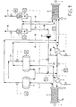
- The features and the advantages of the method of the present invention will become clearer from the following description of an example for carrying out the same with reference to an apparatus for the storage and redistribution on electrical energy schematically shown in an indicative and non-limiting way in the single figure 1 of the attached drawing.
- With reference to the aforesaid figure 1, an apparatus for the storage and redistribution of electrical energy according to the method of the present invention comprises an
electrolyzer 1, made of a plurality ofelectrolytic cells 1a, arranged as a pack and fed, in a per se known way, with a direct electrical current, provided by a not shown power source. - The
cells 1a of said electrolyzer are filled or passed through by a "liquid phase" that provides the water for the electrolysis process which is intended to be carried out. Such liquid phase can be an alkaline or acid solution, or it can be simply water. - The
electrolyzer 1 is structured in order to operate under pressure and is directly in fluid communication, through a duct 2, with apressurised tank 3 for the collection and storage of hydrogen and, through aduct 4, with apressurised tank 5, for the collection and storage of oxygen. - The hydrogen and oxygen, generated in the
electrolyzer 1 in an amount proportional to the direct current that flows through thecells 1a, directly flow to thetanks electrolyzer 1, through aduct 6, after having been previously cooled or warmed through aheat exchanger 7. - A
fuel cell 9 has anodic compartments (not shown), directly in fluid communication with thepressurised tank 3, through aduct 8, in order to be directly fed with hydrogen. The cathodic compartments (not shown, as well) of saidcell 9 are directly in fluid communication with thepressurised tank 5 through aduct 10, in order to be directly fed with oxygen. Even saidfuel cell 9 is filled or passed through by a respective "liquid phase", needed for the electrochemical conversion of hydrogen and oxygen in order to produce water and electrical energy. - The amount of hydrogen consumed for said reconversion depends from the instantaneous requirement of the
fuel cell 9, in terms of electrical energy to be dispensed to a user downstream of it. A small flow of hydrogen is discharged from thefuel cell 9, through aduct 13, aseparator 12 and aduct 11. Onto the bottom of theseparator 12, there is collected the portion of liquid phase possibly entrained by said hydrogen flow from said cell. - Even the surplus of oxygen is discharged from the
fuel cell 9, through aduct 16, after having previously passed through aduct 4 and aseparator 15. - The portions of liquid phase of the
fuel cell 9, collected in theseparators ducts pump 17, after having previously passed through aheat exchanger 19, in order to remove the heat in excess generated in said cell. - According to a first feature of the method according to the present invention, in the
electrolyzer 1 and in thefuel cell 9, a same liquid phase is used. Advantageously, a liquid phase consisting of water or of aqueous solutions of electrolytes, among which there will be preferably strong alkalis, and even more preferably an aqueous solution of potassium hydroxide. - This allows the accomplishment of a second feature of such method, which consists in that the water produced in the
fuel cell 9, as a consequence of the electrochemical reaction between hydrogen and oxygen, is transferred to theelectrolyzer 1, where it is used to produce hydrogen and oxygen. - This task, in fact, is accomplished by the common liquid phase that, in the fuel cell, collects the water produced by the aforesaid electrochemical reaction, water which is then sent to the
electrolyzer 1 by thepump 17 through theseparators ducts pump 17, the liquid phase separated in thetanks cell 9, thus forming a single aqueous flow to be fed to said electrolyzer. - Through a
duct 21, water is introduced in thetank 3 just to compensate the losses associated to the flows of hydrogen and oxygen discharged by theduct - The carrying out of the functional features of the method according to the present invention, i.e.: a single liquid phase for the two electrochemical processes, the use in the electrolysis process of the water produced in the fuel cell, direct communication between the electrolyzer and the storage tanks of hydrogen and oxygen, direct communication between said tanks and the fuel cell, direct communication between said fuel cell and the electrolyzer, allow to obtain an operative unit for the storage and redistribution of electrical energy, which is particularly compact and effective, individually controllable, of great flexibility of use, easy to be transported, with a reduced number of-components and hence of reduced manufacturing costs.
- Further acknowledged advantages, such as for example an improved fuel cell efficiency and an integrated control system for the entire apparatus, derive from the possibility, foreseen and implemented by the present invention, of making also said cell to operate under pressure, in particular at a slightly lower pressure than that of the electrolyzer and of the
tanks - Many modification and variations may be made to the invention thus conceived, all falling within the expertise of a man skilled in the art, and as such falling within the scope of the inventive concept defined by the following claims.
Claims (10)
- Method of storage and redistribution of electrical energy comprising the steps of: producing hydrogen and oxygen through water electrolysis in an electrolyzer (1) operating under pressure; collecting the hydrogen and oxygen so obtained in respective pressurised tanks (3, 5); reconverting into water and electrical energy hydrogen and oxygen, through an electrochemical reaction of the latter in a fuel cell (9) fed from said tanks (3, 5), and characterized by the fact that in said electrolyzer (1) and in said fuel cell (9) a same liquid phase is used, and by the fact that the water produced in said fuel cell (9) by the hydrogen and oxygen reconversion step, is collected in the respective liquid phase and transferred together with the liquid phase to said electrolyzer (1) in order to undergo electrolysis.
- Method according to claim 1, characterized in that said reconversion of hydrogen and oxygen in said fuel cell (9) is carried out under pressure.
- Method according to claim 2, characterized in that the operating pressure of said fuel cell (9) is slightly lower than that of said electrolyzer (1).
- Method according to claim 1, characterized in that said electrolyzer (1) is in direct communication with said tanks (3, 5), to which the hydrogen and oxygen obtained through water electrolysis are directly sent, and said tanks (3, 5) are in direct communication with said fuel cell (9), the hydrogen being directly fed to the anodic compartments thereof and the oxygen to the cathodic compartments thereof, respectively.
- Method according to claim 4, characterized in that portions of the liquid phase of said electrolyzer (1) entrained into said tanks (3, 5) by the hydrogen and oxygen, respectively, are separated and collected in the tanks themselves and recycled to said electrolyzer (1), after having been previously cooled in an appropriate heat exchanger (7).
- Method according to claim 4, characterized in that the hydrogen and oxygen in excess fed to said fuel cell (9) are discharged from the cell itself, whereby portions of liquid phase possibly entrained in hydrogen and oxygen are previously separated, said portions being recycled in part to said cell (9) and in part to said electrolyzer (1), after having been previously cooled or warmed in respective heat exchangers (9, 7).
- Method according to any one of the preceding claims, characterized in that said liquid phase consists of an alkaline aqueous solution.
- Method according to claim 7, characterized in that said liquid phase consists of water or aqueous solutions of electrolytes, among which there are preferably strong alkalis.
- Apparatus for the storage and redistribution of electrical energy according to the method of the preceding claims, characterized in that it comprises a water electrolyzer (1) provided with a respective liquid phase and operating under a predetermined pressure, pressurised tanks (3, 5) in direct fluid communication with said electrolyzer (1) in order to directly receive from it hydrogen and oxygen flows, respectively, a fuel cell (9), provided with a respective liquid phase and operating under a predetermined pressure, said cell (9) having anodic and cathodic compartments in direct fluid communication with said hydrogen and oxygen tanks (3, 5), respectively, and in direct fluid communication with said electrolyzer (1), the liquid phases of said electrolyzer (1) and of said cell (9) being identical.
- Apparatus according to claim 9, characterized in that said mutually directly interconnected electrolyzer (1), fuel cell (9) and tanks (3, 5) form an individually controllable unit.
Priority Applications (4)
| Application Number | Priority Date | Filing Date | Title |
|---|---|---|---|
| ES01113229.7T ES2569950T3 (en) | 2001-05-30 | 2001-05-30 | Method and apparatus for storage and redistribution of electrical energy |
| EP01113229.7A EP1263072B1 (en) | 2001-05-30 | 2001-05-30 | Method and apparatus for the storage and redistribution of electrical energy |
| CA2387847A CA2387847C (en) | 2001-05-30 | 2002-05-29 | Method and apparatus for the storage and redistribution of electrical energy |
| US10/156,030 US7112380B2 (en) | 2001-05-30 | 2002-05-29 | Method and apparatus for the storage and redistribution of electrical energy |
Applications Claiming Priority (1)
| Application Number | Priority Date | Filing Date | Title |
|---|---|---|---|
| EP01113229.7A EP1263072B1 (en) | 2001-05-30 | 2001-05-30 | Method and apparatus for the storage and redistribution of electrical energy |
Publications (2)
| Publication Number | Publication Date |
|---|---|
| EP1263072A1 true EP1263072A1 (en) | 2002-12-04 |
| EP1263072B1 EP1263072B1 (en) | 2016-04-06 |
Family
ID=8177590
Family Applications (1)
| Application Number | Title | Priority Date | Filing Date |
|---|---|---|---|
| EP01113229.7A Expired - Lifetime EP1263072B1 (en) | 2001-05-30 | 2001-05-30 | Method and apparatus for the storage and redistribution of electrical energy |
Country Status (4)
| Country | Link |
|---|---|
| US (1) | US7112380B2 (en) |
| EP (1) | EP1263072B1 (en) |
| CA (1) | CA2387847C (en) |
| ES (1) | ES2569950T3 (en) |
Cited By (3)
| Publication number | Priority date | Publication date | Assignee | Title |
|---|---|---|---|---|
| EP1657774A1 (en) * | 2004-11-04 | 2006-05-17 | Environment Park S.P.A. Parco Scientifico Tecnologico Per l'Ambiente | Regenerative energetic fuel-cell system and process for controlling and managing such system |
| CN112725825A (en) * | 2020-11-27 | 2021-04-30 | 东华工程科技股份有限公司 | Method for preparing glyoxylic acid by electrolyzing oxalic acid |
| EP4650488A1 (en) * | 2024-05-16 | 2025-11-19 | TotalEnergies OneTech | Hydrogen and oxygen depleting system within a water electrolysis installation and related process |
Families Citing this family (12)
| Publication number | Priority date | Publication date | Assignee | Title |
|---|---|---|---|---|
| US7224080B2 (en) * | 2004-07-09 | 2007-05-29 | Schlumberger Technology Corporation | Subsea power supply |
| US20060194086A1 (en) * | 2005-02-25 | 2006-08-31 | Kuai-Teng Hsu | Inverse recycle power system |
| UA85577C2 (en) * | 2006-08-04 | 2009-02-10 | Константин Иванович Луданов | Method for converting heat directly into electric power |
| US20100276278A1 (en) * | 2009-04-30 | 2010-11-04 | Doug Bender | Modular electrolysis device |
| EP2433903B1 (en) * | 2009-05-21 | 2016-04-20 | Panasonic Intellectual Property Management Co., Ltd. | Hydrogen generation system and hot water production system |
| IT1397856B1 (en) * | 2010-01-27 | 2013-02-04 | Giacomini Spa | "HYDROGEN GENERATOR SYSTEM FOR MULTIPLE USES" |
| JP6745092B2 (en) | 2015-06-17 | 2020-08-26 | デノラ・ペルメレック株式会社 | Water treatment system using alkaline water electrolysis device and alkaline fuel cell and water treatment method using the water treatment system |
| CA2933996A1 (en) * | 2016-06-27 | 2017-12-27 | Marvin Milos | Clean energy production method and apparatus |
| DE102018133198A1 (en) * | 2018-12-20 | 2020-06-25 | Hps Home Power Solutions Gmbh | Energy system and method for pressure adjustment in an energy system |
| WO2020246952A1 (en) * | 2019-06-03 | 2020-12-10 | Strain David Joseph | System and method for storage and retrieval of energy |
| CN113106476A (en) * | 2021-03-19 | 2021-07-13 | 嘉寓氢能源科技(辽宁)有限公司 | System for producing hydrogen by utilizing electric electrolytic cell of photovoltaic power plant |
| US12184219B2 (en) * | 2023-04-06 | 2024-12-31 | Charles Robert Wilson | Hydro-electrolysis thermal electricity generation system and method |
Citations (5)
| Publication number | Priority date | Publication date | Assignee | Title |
|---|---|---|---|---|
| US5407756A (en) * | 1992-07-15 | 1995-04-18 | Rockwell International Corporation | Anode assembly for a variable pressure passive regenerative fuel cell system |
| JPH09120831A (en) * | 1995-10-24 | 1997-05-06 | Mitsubishi Heavy Ind Ltd | Power generation / electric storage device for space |
| JPH1055816A (en) * | 1996-08-08 | 1998-02-24 | Fuji Electric Co Ltd | Hydrogen storage power generation system |
| JPH11354132A (en) * | 1998-06-05 | 1999-12-24 | Ishikawajima Harima Heavy Ind Co Ltd | Fuel cell power generation equipment |
| JP2001130901A (en) * | 1999-11-02 | 2001-05-15 | Mitsubishi Corp | Hydrogen energy supply device |
Family Cites Families (10)
| Publication number | Priority date | Publication date | Assignee | Title |
|---|---|---|---|---|
| US3070703A (en) * | 1960-04-07 | 1962-12-25 | United Aircraft Corp | Solar energy powerplant |
| CH472133A (en) * | 1966-11-25 | 1969-04-30 | Varta Ag | Electric power supply system with a wind power generator |
| US3956013A (en) * | 1973-03-30 | 1976-05-11 | Fuji Electric Company Ltd. | Fuel cell |
| US4087976A (en) * | 1976-08-13 | 1978-05-09 | Massachusetts Institute Of Technology | Electric power plant using electrolytic cell-fuel cell combination |
| US4305793A (en) * | 1979-10-22 | 1981-12-15 | Broniewski Bogdan M | Method of concentrating alkali metal hydroxide in hybrid cells having cation selective membranes |
| US4235693A (en) * | 1979-11-09 | 1980-11-25 | The United States Of America As Represented By The Secretary Of The Navy | Submersible energy storage apparatus |
| US4490232A (en) * | 1981-10-29 | 1984-12-25 | The Laitram Corporation | Wave-powered electrolysis of water |
| US5041197A (en) * | 1987-05-05 | 1991-08-20 | Physical Sciences, Inc. | H2 /C12 fuel cells for power and HCl production - chemical cogeneration |
| AU2001294855A1 (en) * | 2000-09-28 | 2002-04-08 | Proton Energy Systems, Inc. | Regenerative electrochemical cell system and method for use thereof |
| JP4232137B2 (en) * | 2001-05-08 | 2009-03-04 | スズキ株式会社 | Fuel cell |
-
2001
- 2001-05-30 EP EP01113229.7A patent/EP1263072B1/en not_active Expired - Lifetime
- 2001-05-30 ES ES01113229.7T patent/ES2569950T3/en not_active Expired - Lifetime
-
2002
- 2002-05-29 US US10/156,030 patent/US7112380B2/en not_active Expired - Lifetime
- 2002-05-29 CA CA2387847A patent/CA2387847C/en not_active Expired - Lifetime
Patent Citations (5)
| Publication number | Priority date | Publication date | Assignee | Title |
|---|---|---|---|---|
| US5407756A (en) * | 1992-07-15 | 1995-04-18 | Rockwell International Corporation | Anode assembly for a variable pressure passive regenerative fuel cell system |
| JPH09120831A (en) * | 1995-10-24 | 1997-05-06 | Mitsubishi Heavy Ind Ltd | Power generation / electric storage device for space |
| JPH1055816A (en) * | 1996-08-08 | 1998-02-24 | Fuji Electric Co Ltd | Hydrogen storage power generation system |
| JPH11354132A (en) * | 1998-06-05 | 1999-12-24 | Ishikawajima Harima Heavy Ind Co Ltd | Fuel cell power generation equipment |
| JP2001130901A (en) * | 1999-11-02 | 2001-05-15 | Mitsubishi Corp | Hydrogen energy supply device |
Non-Patent Citations (7)
| Title |
|---|
| BARON F ET AL: "EUROPEAN REGENERATIVE FUEL CELL TECHNOLOGY FOR SPACE USE", EUROPEAN SPACE POWER. MADRID, OCT. 2 - 6, 1989, PROCEEDINGS OF THE EUROPEAN SPACE POWER CONFERENCE, NOORDWIJK, ESA PUBLICATIONS, NL, VOL. VOL. 1, PAGE(S) 221-226, XP000163951 * |
| PATENT ABSTRACTS OF JAPAN vol. 1997, no. 09 30 September 1997 (1997-09-30) * |
| PATENT ABSTRACTS OF JAPAN vol. 1998, no. 06 30 April 1998 (1998-04-30) * |
| PATENT ABSTRACTS OF JAPAN vol. 2000, no. 03 30 March 2000 (2000-03-30) * |
| PATENT ABSTRACTS OF JAPAN vol. 2000, no. 22 9 March 2001 (2001-03-09) * |
| TILLMETZ W ET AL: "REGENERATIVE FUEL CELLS FOR SPACE AND TERRESTRIAL USE", PROCEEDINGS OF THE 25TH INTERSOCIETY ENERGY CONVERSION ENGINEERING CONFERENCE. IECEC-90. RENO, AUG. 12 - 17, 1990, PROCEEDINGS OF THE INTERSOCIETY ENERGY CONVERSION ENGINEERING CONFERENCE, NEW YORK, IEEE, US, VOL. VOL. 3 CONF. 25, PAGE(S) 154-158, XP000215922 * |
| W.L HUGHES ET AL: "An Energy System For the Future", IEEE TRANSACTIONS ON INDUSTRIAL ELECTRONICS IE-10, no. 1, May 1963 (1963-05-01), pages 108 - 111, XP001031023 * |
Cited By (3)
| Publication number | Priority date | Publication date | Assignee | Title |
|---|---|---|---|---|
| EP1657774A1 (en) * | 2004-11-04 | 2006-05-17 | Environment Park S.P.A. Parco Scientifico Tecnologico Per l'Ambiente | Regenerative energetic fuel-cell system and process for controlling and managing such system |
| CN112725825A (en) * | 2020-11-27 | 2021-04-30 | 东华工程科技股份有限公司 | Method for preparing glyoxylic acid by electrolyzing oxalic acid |
| EP4650488A1 (en) * | 2024-05-16 | 2025-11-19 | TotalEnergies OneTech | Hydrogen and oxygen depleting system within a water electrolysis installation and related process |
Also Published As
| Publication number | Publication date |
|---|---|
| US7112380B2 (en) | 2006-09-26 |
| CA2387847C (en) | 2012-09-18 |
| ES2569950T3 (en) | 2016-05-13 |
| US20020195349A1 (en) | 2002-12-26 |
| CA2387847A1 (en) | 2002-11-30 |
| EP1263072B1 (en) | 2016-04-06 |
Similar Documents
| Publication | Publication Date | Title |
|---|---|---|
| EP1263072B1 (en) | Method and apparatus for the storage and redistribution of electrical energy | |
| CN106784960B (en) | An integrated reversible fuel cell system | |
| CN102099507B (en) | Electrolyser module | |
| JP5908457B2 (en) | Equipment for electrical energy storage and restoration | |
| US20130140171A1 (en) | Electrolyser module | |
| CN111417745A (en) | Electrolysis Units and Electrolyzers | |
| WO2017169204A1 (en) | Hydrogen production system | |
| CN114777413A (en) | System and method for co-producing ammonia electricity by using renewable energy sources | |
| US20230279569A1 (en) | Arrangement to optimize the production of hydrogen | |
| US20050211567A1 (en) | Apparatus and method for integrated hypochlorite and hydrogen fuel production and electrochemical power generation | |
| US20130001070A1 (en) | Electrolyser module | |
| CN111118525B (en) | Electrolytic tank suitable for pressurizing circulating pump shell and working method thereof | |
| WO2023118451A2 (en) | Modular electrochemical system | |
| CN211295278U (en) | Distributed fuel cell power generation system | |
| CN220767185U (en) | Marine water electrolysis hydrogen production equipment and system | |
| CN218561628U (en) | Hydrogen production and hydrogenation process system based on photovoltaic power generation along highway | |
| CN118569525A (en) | Multi-time scale optimization operation method of virtual energy pool for power-green hydrogen chemical industry | |
| CN113908670B (en) | Boiler flue gas treatment system and method based on wind energy | |
| CN101859918A (en) | Method for converting off-grid discontinuous and unstable carbon-free electric energy into mobile storage electric energy | |
| US20240322209A1 (en) | Electrochemical reactor suitable for producing hydrogen on demand and comprising an improved device for storing and supplying hydrogen | |
| CN117273277A (en) | A method to quantify desalination plant flexibility | |
| US10312539B1 (en) | System and method for storage and retrieval of energy | |
| KR101149509B1 (en) | Apparatus for load following fuel cell power generation system in a ship and method thereof | |
| EP4376249A1 (en) | Hydrogen production apparatus, electrical energy supply arrangement and method for operating a hydrogen production apparatus | |
| WO2005033366A1 (en) | Method of producing hydrogen and device therefor |
Legal Events
| Date | Code | Title | Description |
|---|---|---|---|
| PUAI | Public reference made under article 153(3) epc to a published international application that has entered the european phase |
Free format text: ORIGINAL CODE: 0009012 |
|
| AK | Designated contracting states |
Kind code of ref document: A1 Designated state(s): AT BE CH CY DE DK ES FI FR GB GR IE IT LI LU MC NL PT SE TR |
|
| AX | Request for extension of the european patent |
Free format text: AL;LT;LV;MK;RO;SI |
|
| 17P | Request for examination filed |
Effective date: 20030507 |
|
| AKX | Designation fees paid |
Designated state(s): AT BE CH CY DE DK ES FI FR GB GR IE IT LI LU MC NL PT SE TR |
|
| RAP1 | Party data changed (applicant data changed or rights of an application transferred) |
Owner name: CASALE CHEMICALS S.A. |
|
| 17Q | First examination report despatched |
Effective date: 20090619 |
|
| RAP1 | Party data changed (applicant data changed or rights of an application transferred) |
Owner name: CASALE SA |
|
| RAP1 | Party data changed (applicant data changed or rights of an application transferred) |
Owner name: CASALE SA |
|
| GRAP | Despatch of communication of intention to grant a patent |
Free format text: ORIGINAL CODE: EPIDOSNIGR1 |
|
| RIC1 | Information provided on ipc code assigned before grant |
Ipc: C25B 1/04 20060101ALI20151022BHEP Ipc: H01M 8/06 20060101AFI20151022BHEP Ipc: C25B 15/08 20060101ALI20151022BHEP |
|
| INTG | Intention to grant announced |
Effective date: 20151113 |
|
| GRAS | Grant fee paid |
Free format text: ORIGINAL CODE: EPIDOSNIGR3 |
|
| GRAA | (expected) grant |
Free format text: ORIGINAL CODE: 0009210 |
|
| AK | Designated contracting states |
Kind code of ref document: B1 Designated state(s): AT BE CH CY DE DK ES FI FR GB GR IE IT LI LU MC NL PT SE TR |
|
| REG | Reference to a national code |
Ref country code: GB Ref legal event code: FG4D |
|
| REG | Reference to a national code |
Ref country code: AT Ref legal event code: REF Ref document number: 788660 Country of ref document: AT Kind code of ref document: T Effective date: 20160415 Ref country code: CH Ref legal event code: EP |
|
| REG | Reference to a national code |
Ref country code: IE Ref legal event code: FG4D |
|
| REG | Reference to a national code |
Ref country code: FR Ref legal event code: PLFP Year of fee payment: 16 |
|
| REG | Reference to a national code |
Ref country code: DE Ref legal event code: R096 Ref document number: 60149852 Country of ref document: DE |
|
| REG | Reference to a national code |
Ref country code: ES Ref legal event code: FG2A Ref document number: 2569950 Country of ref document: ES Kind code of ref document: T3 Effective date: 20160513 |
|
| REG | Reference to a national code |
Ref country code: CH Ref legal event code: NV Representative=s name: ING. MARCO ZARDI C/O M. ZARDI AND CO. S.A., CH |
|
| REG | Reference to a national code |
Ref country code: NL Ref legal event code: FP |
|
| PG25 | Lapsed in a contracting state [announced via postgrant information from national office to epo] |
Ref country code: FI Free format text: LAPSE BECAUSE OF FAILURE TO SUBMIT A TRANSLATION OF THE DESCRIPTION OR TO PAY THE FEE WITHIN THE PRESCRIBED TIME-LIMIT Effective date: 20160406 |
|
| PG25 | Lapsed in a contracting state [announced via postgrant information from national office to epo] |
Ref country code: PT Free format text: LAPSE BECAUSE OF FAILURE TO SUBMIT A TRANSLATION OF THE DESCRIPTION OR TO PAY THE FEE WITHIN THE PRESCRIBED TIME-LIMIT Effective date: 20160808 Ref country code: SE Free format text: LAPSE BECAUSE OF FAILURE TO SUBMIT A TRANSLATION OF THE DESCRIPTION OR TO PAY THE FEE WITHIN THE PRESCRIBED TIME-LIMIT Effective date: 20160406 Ref country code: GR Free format text: LAPSE BECAUSE OF FAILURE TO SUBMIT A TRANSLATION OF THE DESCRIPTION OR TO PAY THE FEE WITHIN THE PRESCRIBED TIME-LIMIT Effective date: 20160707 |
|
| REG | Reference to a national code |
Ref country code: DE Ref legal event code: R097 Ref document number: 60149852 Country of ref document: DE |
|
| PG25 | Lapsed in a contracting state [announced via postgrant information from national office to epo] |
Ref country code: DK Free format text: LAPSE BECAUSE OF FAILURE TO SUBMIT A TRANSLATION OF THE DESCRIPTION OR TO PAY THE FEE WITHIN THE PRESCRIBED TIME-LIMIT Effective date: 20160406 Ref country code: MC Free format text: LAPSE BECAUSE OF FAILURE TO SUBMIT A TRANSLATION OF THE DESCRIPTION OR TO PAY THE FEE WITHIN THE PRESCRIBED TIME-LIMIT Effective date: 20160406 |
|
| PLBE | No opposition filed within time limit |
Free format text: ORIGINAL CODE: 0009261 |
|
| STAA | Information on the status of an ep patent application or granted ep patent |
Free format text: STATUS: NO OPPOSITION FILED WITHIN TIME LIMIT |
|
| REG | Reference to a national code |
Ref country code: IE Ref legal event code: MM4A |
|
| 26N | No opposition filed |
Effective date: 20170110 |
|
| REG | Reference to a national code |
Ref country code: FR Ref legal event code: PLFP Year of fee payment: 17 |
|
| PG25 | Lapsed in a contracting state [announced via postgrant information from national office to epo] |
Ref country code: IE Free format text: LAPSE BECAUSE OF NON-PAYMENT OF DUE FEES Effective date: 20160530 |
|
| REG | Reference to a national code |
Ref country code: FR Ref legal event code: PLFP Year of fee payment: 18 |
|
| PG25 | Lapsed in a contracting state [announced via postgrant information from national office to epo] |
Ref country code: CY Free format text: LAPSE BECAUSE OF FAILURE TO SUBMIT A TRANSLATION OF THE DESCRIPTION OR TO PAY THE FEE WITHIN THE PRESCRIBED TIME-LIMIT Effective date: 20160406 |
|
| PG25 | Lapsed in a contracting state [announced via postgrant information from national office to epo] |
Ref country code: LU Free format text: LAPSE BECAUSE OF NON-PAYMENT OF DUE FEES Effective date: 20160530 Ref country code: TR Free format text: LAPSE BECAUSE OF FAILURE TO SUBMIT A TRANSLATION OF THE DESCRIPTION OR TO PAY THE FEE WITHIN THE PRESCRIBED TIME-LIMIT Effective date: 20160406 |
|
| REG | Reference to a national code |
Ref country code: AT Ref legal event code: UEP Ref document number: 788660 Country of ref document: AT Kind code of ref document: T Effective date: 20160406 |
|
| PGFP | Annual fee paid to national office [announced via postgrant information from national office to epo] |
Ref country code: NL Payment date: 20200424 Year of fee payment: 20 Ref country code: FR Payment date: 20200422 Year of fee payment: 20 Ref country code: CH Payment date: 20200422 Year of fee payment: 20 Ref country code: DE Payment date: 20200421 Year of fee payment: 20 Ref country code: ES Payment date: 20200602 Year of fee payment: 20 |
|
| PGFP | Annual fee paid to national office [announced via postgrant information from national office to epo] |
Ref country code: IT Payment date: 20200421 Year of fee payment: 20 Ref country code: GB Payment date: 20200423 Year of fee payment: 20 Ref country code: BE Payment date: 20200423 Year of fee payment: 20 |
|
| PGFP | Annual fee paid to national office [announced via postgrant information from national office to epo] |
Ref country code: AT Payment date: 20200422 Year of fee payment: 20 |
|
| REG | Reference to a national code |
Ref country code: DE Ref legal event code: R071 Ref document number: 60149852 Country of ref document: DE |
|
| REG | Reference to a national code |
Ref country code: CH Ref legal event code: PL |
|
| REG | Reference to a national code |
Ref country code: NL Ref legal event code: MK Effective date: 20210529 |
|
| REG | Reference to a national code |
Ref country code: GB Ref legal event code: PE20 Expiry date: 20210529 |
|
| REG | Reference to a national code |
Ref country code: BE Ref legal event code: MK Effective date: 20210530 |
|
| REG | Reference to a national code |
Ref country code: AT Ref legal event code: MK07 Ref document number: 788660 Country of ref document: AT Kind code of ref document: T Effective date: 20210530 |
|
| PG25 | Lapsed in a contracting state [announced via postgrant information from national office to epo] |
Ref country code: GB Free format text: LAPSE BECAUSE OF EXPIRATION OF PROTECTION Effective date: 20210529 |
|
| PG25 | Lapsed in a contracting state [announced via postgrant information from national office to epo] |
Ref country code: ES Free format text: LAPSE BECAUSE OF EXPIRATION OF PROTECTION Effective date: 20210531 |