EP1262987A2 - Vibration absorbing mechanism - Google Patents
Vibration absorbing mechanism Download PDFInfo
- Publication number
- EP1262987A2 EP1262987A2 EP02253188A EP02253188A EP1262987A2 EP 1262987 A2 EP1262987 A2 EP 1262987A2 EP 02253188 A EP02253188 A EP 02253188A EP 02253188 A EP02253188 A EP 02253188A EP 1262987 A2 EP1262987 A2 EP 1262987A2
- Authority
- EP
- European Patent Office
- Prior art keywords
- vibration absorbing
- elastic member
- restraint
- mounting hole
- elastic
- Prior art date
- Legal status (The legal status is an assumption and is not a legal conclusion. Google has not performed a legal analysis and makes no representation as to the accuracy of the status listed.)
- Granted
Links
Images



Classifications
-
- G—PHYSICS
- G11—INFORMATION STORAGE
- G11B—INFORMATION STORAGE BASED ON RELATIVE MOVEMENT BETWEEN RECORD CARRIER AND TRANSDUCER
- G11B33/00—Constructional parts, details or accessories not provided for in the other groups of this subclass
- G11B33/02—Cabinets; Cases; Stands; Disposition of apparatus therein or thereon
- G11B33/08—Insulation or absorption of undesired vibrations or sounds
-
- F—MECHANICAL ENGINEERING; LIGHTING; HEATING; WEAPONS; BLASTING
- F16—ENGINEERING ELEMENTS AND UNITS; GENERAL MEASURES FOR PRODUCING AND MAINTAINING EFFECTIVE FUNCTIONING OF MACHINES OR INSTALLATIONS; THERMAL INSULATION IN GENERAL
- F16F—SPRINGS; SHOCK-ABSORBERS; MEANS FOR DAMPING VIBRATION
- F16F1/00—Springs
- F16F1/36—Springs made of rubber or other material having high internal friction, e.g. thermoplastic elastomers
- F16F1/373—Springs made of rubber or other material having high internal friction, e.g. thermoplastic elastomers characterised by having a particular shape
- F16F1/3732—Springs made of rubber or other material having high internal friction, e.g. thermoplastic elastomers characterised by having a particular shape having an annular or the like shape, e.g. grommet-type resilient mountings
-
- F—MECHANICAL ENGINEERING; LIGHTING; HEATING; WEAPONS; BLASTING
- F16—ENGINEERING ELEMENTS AND UNITS; GENERAL MEASURES FOR PRODUCING AND MAINTAINING EFFECTIVE FUNCTIONING OF MACHINES OR INSTALLATIONS; THERMAL INSULATION IN GENERAL
- F16F—SPRINGS; SHOCK-ABSORBERS; MEANS FOR DAMPING VIBRATION
- F16F7/00—Vibration-dampers; Shock-absorbers
- F16F7/10—Vibration-dampers; Shock-absorbers using inertia effect
- F16F7/104—Vibration-dampers; Shock-absorbers using inertia effect the inertia member being resiliently mounted
- F16F7/108—Vibration-dampers; Shock-absorbers using inertia effect the inertia member being resiliently mounted on plastics springs
Definitions
- the present invention relates to a vibration absorbing mechanism, and more particularly to a vibration absorbing mechanism that is suitably applied to a recording/reproducing device having a vibration isolating mechanism to isolate the vibration produced by a spindle and a recording medium such as an optical disk mounted on the spindle when rotated.
- a recording/reproducing device using a recording medium rotating at high speed is employed in a computer or various players.
- an optical disk reproducing device for reproducing an optical disk such as a CD (Compact Disk) player (including a CD-ROM drive) or a DVD (Video Disk) player is widely employed.
- CD Compact Disk
- DVD Video Disk
- An optical system or servo system in this optical disk reproducing device has a limited ability of making the accurate track control and focusing control against the vibration applied from the outside of the device or produced by the device itself. Especially when it is employed for a storage device in the computer, the vibration produced by the device itself to speed up a drive unit for fast reading or seeking becomes an important problem.
- a structure is generally employed in which an entire mechanism or a reproducing mechanism (optical system mechanism) is supported by an elastic member, and an external vibration is attenuated by the internal resistance of its elastic member. Also, another structure for attenuating the vibration produced by the device itself is employed. This vibration attenuating structure is shown in Figs. 10 and 11.
- Figs. 10 and 11 show a CD player as one example of the device having a structure for attenuating the external vibration and internal vibration.
- Fig. 10 is a schematic plan view showing the internal structure of a CD player
- Fig. 11 is a cross-sectional view of a portion of the CD player taken along the line D-D in Fig. 10.
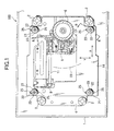
- a main frame 104 is resiliently supported via the first elastic members 102 (four elasticmembers shown in the figure) on a housing 101. Also, a sub-frame 132 is attached via the second elastic members 131 on the main frame 104. On this main frame 104, a drive system with a spindle motor having a turntable 106 for rotating an optical disk 10 (indicated by the imaginary line) is mounted.
- a connection structure between this sub-frame 132 and the main frame 104 is such that the sub-frame 132 is fixed to the main frame 104 by a screw 122 with which a second elastic member 131 is engaged with the main frame 104, in which an outer circumferential face 131a of this second elastic member 131 is constrained by a mounting hole 133 of the sub-frame 132, as shown in Fig. 11.
- the main frame 104 is provided with two guide rails 111 (only one shown) parallel to each other.
- a pickup 105 engaging the guide rails 111 is disposed to be movable along the guide rails 111 in a radial direction of the optical disk. This pickup 105 is engaged by a drive screw 108 connected to a stepping motor 109 and can be moved in the radial direction of the optical disk.
- the vibration produced by the device itself can be suppressed by a vibration suppressing structure using the sub-frame 132 that is dynamic vibration absorbing member.
- the resonance frequency is set in such a way as to increase or decrease the clamping force of the screw 122 to change a restraint of the second elastic member 131 between the screw 122 and the main frame 104, and change an abutment force (force of the mounting hole constraining the elastic member) of the outer circumferential face 131a of the second elastic member 131 against the mounting hole 133.
- the resonance frequency is tuned in respect of any one of a focus direction (vertical direction to the surface of the optical disk, or direction of the arrow Z in the figure), a track direction (rotational direction of the optical disk as indicated by the arrow Y in the figure) , a tangential direction (radial direction of the optical disk as indicated by the arrow X in the figure) to produce the vibration suppressing effect, resulting in a highly empirical adjustment operation.
- the vibration suppressing effect is easily obtained in a specific direction or a plurality of directions, the vibration suppressing action can be minutely adjusted in various types of devices, enabling the fast reading (writing) and promoting the miniaturization and lighter weight of the device.
- the vibration suppressing effect it was very difficult to set the vibration suppressing effect in a plurality of directions.
- the present invention is achieved in the light of the above problems, and it is an object of the invention to provide a vibration absorbing mechanism for suppressing the vibration caused by drive member in a recording/reproducing device for a recording medium such as an optical disk, in which the vibration suppressing effect can be easily obtained in a plurality of directions, and the fast reading (writing) can be made more stably than conventionally.
- a vibration absorbing mechanism comprising mount member for mounting drive member for driving the rotation of an information recording medium and information reading member for reading the information of the information recording medium, and dynamic vibration absorbing member, connected via the mount member and an elastic member, for attenuating the vibration of the mount member, characterized in that the dynamic vibration absorbing member is connected with the elastic member via a wall face constraining an outer circumferential face of the elastic member, and restraint changing member for changing a restraint of the wall face on the elastic member in a specific direction is provided between the elastic member and the dynamic vibration absorbing member.
- the mount member and the dynamic vibration absorbing member are linked via the elastic member, so that the vibration produced by a drive system mounted on the mount member can be suitably attenuated.
- a decrease or increase in the restraint can be partially produced in an area of the elastic member constrained by the wall face, where the restraint changing member is provided.
- the resonance frequency can be varied in the specific direction, depending on the position at which the restraint changing member is formed.
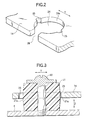
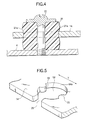
- the vibration absorbing mechanism characterized in that the dynamic vibration absorbing member is provided with a mounting hole for accepting the elastic member, and the restraint changing member is a concave portion of the mounting hole on the wall face.
- the wall face of the mounting hole formed in the dynamic vibration absorbing member is contacted with the circumference of the elastic member, so that the mount member and the dynamic vibration absorbing member are resiliently connected. Furthermore, the concave portion formed on the wall face of the mounting hole weakens or releases the restraint of the elastic member, thereby acting as the restraint changing member for weakening the restraint in the concave portion, and making it possible to vary the resonance vibration frequency in a direction where the restraint is weakened.
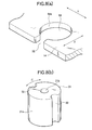
- the vibration absorbing mechanism characterized in that the dynamic vibration absorbing member is provided with a mounting hole for accepting the elastic member, and the restraint changing member is aprojection portion of the mounting hole on the wall face.
- the wall face of the mounting hole formed in the dynamic vibration absorbing member is contacted with the circumference of the elastic member, so that the mount member and the dynamic vibration absorbing member are resiliently connected. Furthermore, the projection portion formed on the wall face of the mounting hole acts as the restraint changing member for partially restraining the surface of the elastic member strongly, making it possible to vary the resonance vibration frequency in a specific direction where the restraint is strengthened.
- the vibration absorbing mechanism characterized in that the dynamic vibration absorbing member is provided with a mounting hole for accepting the elastic member, and the restraint changing member is a recessed portion of the elastic member.
- the elastic member is accepted in the mounting hole formed in the dynamic vibration absorbing member and constrained by the wall face of the mounting hole, so that the mount member and the dynamic vibration absorbing member are resiliently connected. Furthermore, the recessed portion of the elastic member can weaken or release the restraint of the elastic member, acting as the restraint changing member that weakens the restraint in the recessed portion, making it possible to vary the resonance vibration frequency in a specific direction where the restraint is weakened.
- the vibration absorbing mechanism characterized in that the dynamic vibration absorbing member is provided with a mounting hole for accepting the elastic member, and the restraint changing member is an elastic projection portion of the elastic member.
- the wall face of the mounting hole formed in the dynamic vibration absorbing member is contacted with the circumference of the elastic member, so that the mount member and the dynamic vibration absorbing member are resiliently connected. Furthermore, the elastic projection portion formed on the outer circumferential face of the elastic member acts as the restraint changing member for partially restraining the elastic member itself strongly, making it possible to vary the resonance vibration frequency in a specific direction where the restraint is strengthened.
- the vibration absorbing mechanism according to the fourth or fifth aspect of the invention, characterized in that the elastic member is almost cylindrical, in which a fixing direction of he elastic member to the mount member is selectable by a fixing member passing through a central portion.
- the wall face of the mounting hole formed in the dynamic vibration absorbing member is contacted with the circumference of the elastic member, so that the mount member and the dynamic vibration absorbing member are resiliently connected. Furthermore, the elastic projection portion formed on the outer circumferential face of the elastic member acts as the restraint changing member for partially restraining the elastic member itself strongly, making it possible to vary the resonance vibration frequency in a specific direction where the restraint is strengthened. Thereby, the vibration suppressing effect can be easily set in the specific direction without using the complex constitution, and the vibration absorbing mechanism can be provided to allow the fast reading (writing) to be made more stably than conventionally.
- the elastic member is almost cylindrical, and attached by the fixing member passing through the central portion, whereby the fixing direction of the elastic member to the mount member is selectable.
- the position of restraint changing member formed in the elastic member can be chosen so that the resonance vibration frequency can be varied at will in the direction.
- the vibration suppressing effect can be easily set in the specific direction, and the vibration absorbing mechanism can be provided to allow the fast reading (writing) to be made more stably than conventionally.
Landscapes
- Engineering & Computer Science (AREA)
- General Engineering & Computer Science (AREA)
- Mechanical Engineering (AREA)
- Vibration Prevention Devices (AREA)
- Optical Recording Or Reproduction (AREA)
Abstract
Description
mount member for mounting drive member for driving the rotation of an information recording medium and information reading member for reading the information of the information recording medium, and dynamic vibration absorbing member, connected via the mount member and an elastic member, for attenuating the vibration of the mount member, characterized in that the dynamic vibration absorbing member is connected with the elastic member via a wall face constraining an outer circumferential face of the elastic member, and restraint changing member for changing a restraint of the wall face on the elastic member in a specific direction is provided between the elastic member and the dynamic vibration absorbing member.
Claims (7)
- A vibration absorbing mechanism comprising:drive member for driving rotation of an information recording medium;information reading member for reading the information of the information recording medium;mount member for mounting said drive member and said information reading member; anddynamic vibration absorbing member, connected via said mount member and an elastic member, for attenuating the vibration of said mount member; whereinsaid dynamic vibration absorbing member is connected with said elastic member via a wall face constraining an outer circumferential face of said elastic member, andrestraint changing member for changing a restraint of said wall face on said elastic member in a specific direction is provided between said elastic member and said dynamic vibration absorbing member.
- The vibration absorbing mechanism according to claim 1, wherein
said dynamic vibration absorbing member is provided with a mounting hole for accepting said elastic member, and
said restraint changing member is a concave portion of the mounting hole on the wall face. - The vibration absorbing mechanism according to claim 1, wherein
said dynamic vibration absorbing member is provided with a mounting hole for accepting said elastic member, and
said restraint changing member is a projection portion of the mounting hole on the wall face. - The vibration absorbing mechanism according to claim 1, wherein
said dynamic vibration absorbing member is provided with a mounting hole for accepting said elastic member, and
said restraint changing member is a recessed portion of said elastic member. - The vibration absorbing mechanism according to claim 1, wherein
said dynamic vibration absorbing member is provided with a mounting hole for accepting said elastic member, and
said restraint changing member is an elastic projection portion of said elastic member. - The vibration absorbing mechanism according to claim 4, wherein
aid elastic member is almost cylindrical, inwhicha fixing direction of said elastic member to said mount member is selectable by a fixing member passing through a central portion. - The vibration absorbing mechanism according to claim 5, wherein
aidelasticmember is almost cylindrical, inwhicha fixing direction of said elastic member to said mount member is selectable by a fixing member passing through a central portion.
Applications Claiming Priority (2)
| Application Number | Priority Date | Filing Date | Title |
|---|---|---|---|
| JP2001158389 | 2001-05-28 | ||
| JP2001158389A JP2002352572A (en) | 2001-05-28 | 2001-05-28 | Vibration absorbing mechanism |
Publications (3)
| Publication Number | Publication Date |
|---|---|
| EP1262987A2 true EP1262987A2 (en) | 2002-12-04 |
| EP1262987A3 EP1262987A3 (en) | 2003-01-22 |
| EP1262987B1 EP1262987B1 (en) | 2005-07-27 |
Family
ID=19002123
Family Applications (1)
| Application Number | Title | Priority Date | Filing Date |
|---|---|---|---|
| EP02253188A Expired - Lifetime EP1262987B1 (en) | 2001-05-28 | 2002-05-07 | Vibration absorbing mechanism |
Country Status (4)
| Country | Link |
|---|---|
| US (1) | US20020176350A1 (en) |
| EP (1) | EP1262987B1 (en) |
| JP (1) | JP2002352572A (en) |
| DE (1) | DE60205178T2 (en) |
Cited By (1)
| Publication number | Priority date | Publication date | Assignee | Title |
|---|---|---|---|---|
| WO2004061326A1 (en) * | 2002-12-17 | 2004-07-22 | Cabot Safety Intermediate Corporation | Elastomeric pin isolator |
Families Citing this family (7)
| Publication number | Priority date | Publication date | Assignee | Title |
|---|---|---|---|---|
| JP3810715B2 (en) * | 2002-07-30 | 2006-08-16 | 松下電器産業株式会社 | Disc changer device |
| TW594679B (en) * | 2003-04-07 | 2004-06-21 | Benq Corp | Horizontal postion adjustment mechanism and method thereof |
| JP2007172785A (en) * | 2005-12-26 | 2007-07-05 | Matsushita Electric Ind Co Ltd | Disk unit |
| US20090125929A1 (en) * | 2006-01-05 | 2009-05-14 | Pioneer Corporation | Optical disc drive device and optical disc apparatus |
| JP5115077B2 (en) * | 2007-07-31 | 2013-01-09 | トヨタ自動車株式会社 | Vehicle cowl top structure |
| US9548144B2 (en) * | 2012-11-16 | 2017-01-17 | Tyco Electronics Corporation | Isolation system for an electronic device |
| TWM508769U (en) * | 2015-06-23 | 2015-09-11 | Cooler Master Technology Inc | Mounting device |
Family Cites Families (7)
| Publication number | Priority date | Publication date | Assignee | Title |
|---|---|---|---|---|
| JPS60182086A (en) * | 1984-02-29 | 1985-09-17 | Hitachi Ltd | Damping device |
| JPH06129488A (en) * | 1992-10-17 | 1994-05-10 | Tokai Rubber Ind Ltd | Anti-vibration device with dynamic vibration absorber |
| DE4447610C2 (en) * | 1994-09-06 | 1997-06-12 | Clouth Gummiwerke Ag | Vibration damper |
| JPH10339354A (en) * | 1997-06-09 | 1998-12-22 | Matsushita Electric Ind Co Ltd | Dynamic vibration reducer and disk storage regenerating device using dynamic vibration reducer |
| US6125097A (en) * | 1998-11-05 | 2000-09-26 | Behavior Tech Computer Corp. | Shock absorbing device of CD-ROM reading mechanism |
| JP2001307340A (en) * | 2000-04-21 | 2001-11-02 | Sony Corp | Disk drive device |
| TW540798U (en) * | 2002-02-22 | 2003-07-01 | Lite On It Corp | Dynamic vibration-damper of CD drive |
-
2001
- 2001-05-28 JP JP2001158389A patent/JP2002352572A/en not_active Abandoned
-
2002
- 2002-05-07 EP EP02253188A patent/EP1262987B1/en not_active Expired - Lifetime
- 2002-05-07 DE DE60205178T patent/DE60205178T2/en not_active Expired - Fee Related
- 2002-05-24 US US10/153,724 patent/US20020176350A1/en not_active Abandoned
Cited By (2)
| Publication number | Priority date | Publication date | Assignee | Title |
|---|---|---|---|---|
| WO2004061326A1 (en) * | 2002-12-17 | 2004-07-22 | Cabot Safety Intermediate Corporation | Elastomeric pin isolator |
| US8474804B2 (en) | 2002-12-17 | 2013-07-02 | Cabot Safety Intermediate Llc | Elastomeric pin isolator |
Also Published As
| Publication number | Publication date |
|---|---|
| DE60205178T2 (en) | 2005-12-29 |
| JP2002352572A (en) | 2002-12-06 |
| EP1262987A3 (en) | 2003-01-22 |
| US20020176350A1 (en) | 2002-11-28 |
| EP1262987B1 (en) | 2005-07-27 |
| DE60205178D1 (en) | 2005-09-01 |
Similar Documents
| Publication | Publication Date | Title |
|---|---|---|
| JP3154141B2 (en) | Buffer device and recording and / or reproducing device for disk-shaped recording medium using buffer device | |
| KR100615466B1 (en) | Disc apparatus | |
| JP3073457B2 (en) | Optical recording / reproducing device | |
| US6205111B1 (en) | Disk driving apparatus for reliably centering a meter-layer optical disk on which information is recorded | |
| EP1262987B1 (en) | Vibration absorbing mechanism | |
| JPH09293325A (en) | Optical recording / reproducing apparatus having means for adjusting the installation angle of a spindle motor | |
| KR100686301B1 (en) | Disc drive and optical disc drive | |
| US6178154B1 (en) | Optical disk device having increased height at an outer periphery of the optical disk | |
| JP3118398B2 (en) | Disk player anti-vibration device | |
| JP3587735B2 (en) | Disk unit | |
| US5218598A (en) | Disc driving apparatus with magnetic means for preventing axial movement | |
| JPH11224482A (en) | Recording and playback device | |
| KR20060113723A (en) | Recording and / or reproducing apparatus for an optical recording medium having means for parallel orientation of the scanning device with respect to the surface of the recording medium | |
| JPH06208785A (en) | Damper and floating mechanism | |
| EP0965125B1 (en) | Reproduction and/or recording device for optical recording media having a unit for adjusting the inclination of a bearing | |
| KR100194350B1 (en) | Vibration Absorption Structure of Optical Pickup Actuator for DVD | |
| JP2004145971A (en) | Electronic devices and equipment | |
| KR100230257B1 (en) | Damping device for optical disc drive | |
| JP3799825B2 (en) | Disk unit | |
| JP3670559B2 (en) | Optical head device | |
| JP3421866B2 (en) | A shaft support mechanism and an optical disk device. | |
| JPH0620457A (en) | Anti-vibration device for disc player | |
| JP2001307338A (en) | Skew adjusting mechanism | |
| JP2003187538A (en) | Optical disk drive | |
| JPH11110949A (en) | Disk reproducing device |
Legal Events
| Date | Code | Title | Description |
|---|---|---|---|
| PUAI | Public reference made under article 153(3) epc to a published international application that has entered the european phase |
Free format text: ORIGINAL CODE: 0009012 |
|
| AK | Designated contracting states |
Kind code of ref document: A2 Designated state(s): AT BE CH CY DE DK ES FI FR GB GR IE IT LI LU MC NL PT SE TR |
|
| AX | Request for extension of the european patent |
Free format text: AL;LT;LV;MK;RO;SI |
|
| PUAL | Search report despatched |
Free format text: ORIGINAL CODE: 0009013 |
|
| AK | Designated contracting states |
Kind code of ref document: A3 Designated state(s): AT BE CH CY DE DK ES FI FR GB GR IE IT LI LU MC NL PT SE TR |
|
| AX | Request for extension of the european patent |
Free format text: AL;LT;LV;MK;RO;SI |
|
| 17P | Request for examination filed |
Effective date: 20030708 |
|
| AKX | Designation fees paid |
Designated state(s): DE FR GB |
|
| 17Q | First examination report despatched |
Effective date: 20040223 |
|
| GRAP | Despatch of communication of intention to grant a patent |
Free format text: ORIGINAL CODE: EPIDOSNIGR1 |
|
| GRAS | Grant fee paid |
Free format text: ORIGINAL CODE: EPIDOSNIGR3 |
|
| GRAA | (expected) grant |
Free format text: ORIGINAL CODE: 0009210 |
|
| AK | Designated contracting states |
Kind code of ref document: B1 Designated state(s): DE FR GB |
|
| REG | Reference to a national code |
Ref country code: GB Ref legal event code: FG4D |
|
| REF | Corresponds to: |
Ref document number: 60205178 Country of ref document: DE Date of ref document: 20050901 Kind code of ref document: P |
|
| ET | Fr: translation filed | ||
| PLBE | No opposition filed within time limit |
Free format text: ORIGINAL CODE: 0009261 |
|
| STAA | Information on the status of an ep patent application or granted ep patent |
Free format text: STATUS: NO OPPOSITION FILED WITHIN TIME LIMIT |
|
| 26N | No opposition filed |
Effective date: 20060428 |
|
| PGFP | Annual fee paid to national office [announced via postgrant information from national office to epo] |
Ref country code: DE Payment date: 20070503 Year of fee payment: 6 |
|
| PGFP | Annual fee paid to national office [announced via postgrant information from national office to epo] |
Ref country code: GB Payment date: 20070502 Year of fee payment: 6 |
|
| PGFP | Annual fee paid to national office [announced via postgrant information from national office to epo] |
Ref country code: FR Payment date: 20070510 Year of fee payment: 6 |
|
| GBPC | Gb: european patent ceased through non-payment of renewal fee |
Effective date: 20080507 |
|
| REG | Reference to a national code |
Ref country code: FR Ref legal event code: ST Effective date: 20090119 |
|
| PG25 | Lapsed in a contracting state [announced via postgrant information from national office to epo] |
Ref country code: DE Free format text: LAPSE BECAUSE OF NON-PAYMENT OF DUE FEES Effective date: 20081202 Ref country code: FR Free format text: LAPSE BECAUSE OF NON-PAYMENT OF DUE FEES Effective date: 20080602 |
|
| PG25 | Lapsed in a contracting state [announced via postgrant information from national office to epo] |
Ref country code: GB Free format text: LAPSE BECAUSE OF NON-PAYMENT OF DUE FEES Effective date: 20080507 |