EP1262630A1 - Dispositif de prélèvement d'air par écoulement centripète - Google Patents
Dispositif de prélèvement d'air par écoulement centripète Download PDFInfo
- Publication number
- EP1262630A1 EP1262630A1 EP02291314A EP02291314A EP1262630A1 EP 1262630 A1 EP1262630 A1 EP 1262630A1 EP 02291314 A EP02291314 A EP 02291314A EP 02291314 A EP02291314 A EP 02291314A EP 1262630 A1 EP1262630 A1 EP 1262630A1
- Authority
- EP
- European Patent Office
- Prior art keywords
- tube
- sampling
- radially
- sampling tube
- collar
- Prior art date
- Legal status (The legal status is an assumption and is not a legal conclusion. Google has not performed a legal analysis and makes no representation as to the accuracy of the status listed.)
- Granted
Links
- 238000005070 sampling Methods 0.000 claims description 31
- 238000013016 damping Methods 0.000 claims description 7
- 230000000717 retained effect Effects 0.000 claims description 4
- 230000002093 peripheral effect Effects 0.000 claims 1
- 238000000605 extraction Methods 0.000 abstract 2
- 238000005452 bending Methods 0.000 description 7
- 239000011324 bead Substances 0.000 description 3
- 239000006096 absorbing agent Substances 0.000 description 2
- 238000003754 machining Methods 0.000 description 2
- 230000035939 shock Effects 0.000 description 2
- 230000000694 effects Effects 0.000 description 1
- 230000005284 excitation Effects 0.000 description 1
- 238000004519 manufacturing process Methods 0.000 description 1
- 238000007789 sealing Methods 0.000 description 1
- 210000002105 tongue Anatomy 0.000 description 1
Images


Classifications
-
- F—MECHANICAL ENGINEERING; LIGHTING; HEATING; WEAPONS; BLASTING
- F04—POSITIVE - DISPLACEMENT MACHINES FOR LIQUIDS; PUMPS FOR LIQUIDS OR ELASTIC FLUIDS
- F04D—NON-POSITIVE-DISPLACEMENT PUMPS
- F04D29/00—Details, component parts, or accessories
- F04D29/58—Cooling; Heating; Diminishing heat transfer
- F04D29/582—Cooling; Heating; Diminishing heat transfer specially adapted for elastic fluid pumps
-
- F—MECHANICAL ENGINEERING; LIGHTING; HEATING; WEAPONS; BLASTING
- F01—MACHINES OR ENGINES IN GENERAL; ENGINE PLANTS IN GENERAL; STEAM ENGINES
- F01D—NON-POSITIVE DISPLACEMENT MACHINES OR ENGINES, e.g. STEAM TURBINES
- F01D5/00—Blades; Blade-carrying members; Heating, heat-insulating, cooling or antivibration means on the blades or the members
- F01D5/02—Blade-carrying members, e.g. rotors
- F01D5/08—Heating, heat-insulating or cooling means
- F01D5/081—Cooling fluid being directed on the side of the rotor disc or at the roots of the blades
- F01D5/082—Cooling fluid being directed on the side of the rotor disc or at the roots of the blades on the side of the rotor disc
-
- F—MECHANICAL ENGINEERING; LIGHTING; HEATING; WEAPONS; BLASTING
- F04—POSITIVE - DISPLACEMENT MACHINES FOR LIQUIDS; PUMPS FOR LIQUIDS OR ELASTIC FLUIDS
- F04D—NON-POSITIVE-DISPLACEMENT PUMPS
- F04D29/00—Details, component parts, or accessories
- F04D29/26—Rotors specially for elastic fluids
- F04D29/32—Rotors specially for elastic fluids for axial flow pumps
- F04D29/321—Rotors specially for elastic fluids for axial flow pumps for axial flow compressors
-
- F—MECHANICAL ENGINEERING; LIGHTING; HEATING; WEAPONS; BLASTING
- F04—POSITIVE - DISPLACEMENT MACHINES FOR LIQUIDS; PUMPS FOR LIQUIDS OR ELASTIC FLUIDS
- F04D—NON-POSITIVE-DISPLACEMENT PUMPS
- F04D29/00—Details, component parts, or accessories
- F04D29/66—Combating cavitation, whirls, noise, vibration or the like; Balancing
- F04D29/661—Combating cavitation, whirls, noise, vibration or the like; Balancing especially adapted for elastic fluid pumps
- F04D29/668—Combating cavitation, whirls, noise, vibration or the like; Balancing especially adapted for elastic fluid pumps damping or preventing mechanical vibrations
-
- Y—GENERAL TAGGING OF NEW TECHNOLOGICAL DEVELOPMENTS; GENERAL TAGGING OF CROSS-SECTIONAL TECHNOLOGIES SPANNING OVER SEVERAL SECTIONS OF THE IPC; TECHNICAL SUBJECTS COVERED BY FORMER USPC CROSS-REFERENCE ART COLLECTIONS [XRACs] AND DIGESTS
- Y02—TECHNOLOGIES OR APPLICATIONS FOR MITIGATION OR ADAPTATION AGAINST CLIMATE CHANGE
- Y02T—CLIMATE CHANGE MITIGATION TECHNOLOGIES RELATED TO TRANSPORTATION
- Y02T50/00—Aeronautics or air transport
- Y02T50/60—Efficient propulsion technologies, e.g. for aircraft
Definitions
- the invention relates to a device for extracting air from a turbomachine compressor.
- a sampling device of air by centripetal flow provided between two discs of a turbomachine compressor, said device comprising a support annular fixed on one face of one of said discs and a plurality of air sampling tubes mounted substantially radially in openings in said support, each tube being equipped with means to reduce the vibrations of said tube during operation of the turbine engine.
- the frequency of 1F mode for the sampling tube centripetal of stage 6 of the GE 90-115 B turbojet engine is 950 Hz.
- This motor comprising 12 sampling tubes the frequency from 8 F mode to 7 125 rpm is 950 Hz (7 125 x 8/60). This frequency is equal to the frequency of the 1F mode.
- a first object of the invention is to reduce the stress dynamic in the collection tube by dissipation of energy from deformation.
- a second object of the invention is to propose a device for air sampling by centripetal flow in which the system vibration damping of the sampling tubes allows significantly increase the frequency of the first bending mode called 1F mode, so that the crossover between 1F mode and the excitation source no longer appears.
- the invention achieves its object by the fact that the means for reduce the vibrations of a sampling tube have a tube shock absorber retained in an orifice of the annular support and surrounding the radially outer part of said sampling tube, the end radially inner of said damper tube enclosing an area corresponding to said sampling tube and an annular space being provided between the middle zone of said damper tube and said tube sample.
- the proposed device allows a reduction of the stress dynamic in the collection tube by dissipation of energy from deformation, and an increase in the frequency of the first mode of bending, known as 1F mode, due to the increase in equivalent stiffness of the collection system.
- the proposed external damper tube being free of slots and holes at the end of the slots, its manufacture is easier than the machining of an internal damping tube with petals.
- the radially end inside of the damper tube is constricted and is in contact with the wall device of the sampling tube according to a plurality of axial zones.
- the sampling tube present in line with the radially inner end of the damping tube, a collar fitting in said end.
- this collar has a plurality of dishes in order to reduce the contact surfaces.
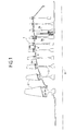
- Figure 1 shows a rotor 1 of a high pressure compressor of an X-axis turbojet engine which comprises several stages of blades 2 mounted on the periphery of discs 3. Two consecutive discs are connected by annular ferrules 4 equipped with wipers 4a ensuring sealing with the inner ends of the fixed vane crowns of the stator.
- the fixed vane crowns are interposed between the crowns of movable blades 2.
- An air sample is taken between two disc stages. This sampled air is used to cool the high pressure turbine which drives the high pressure compressor 1.
- ports 5 are formed in the shell 4 connecting the discs 3a and 3b, downstream of the internal ends of the fixed vanes 6, arranged between the crown vanes 2a of the disc 3a and the crown of vanes 2b of the disc 3b.
- the air sampled through the orifices 5 enters the annular space 7 delimited by the opposite faces of the discs 3a and 3b.
- the downstream disc 3b has in its internal region a collar ring 8 of L-shaped section to which is fixed by bolts 9 a ring 10 of axis X which carries a plurality of air sampling tubes 11 arranged substantially axially.
- the ring 10 has a front radial wall 12 and a rear radial wall 13 connected by a core 14 having a plurality of holes 15 separated by openings rectangular 16.
- the rear radial wall 13 has holes 17 for accommodate the bolts 9, and an annular rib 18 provided for engage under the collar 8 in order to allow the radial positioning of the ring 10.
- the front radial wall 12 also includes a rib annular 19 which is positioned in the vicinity of a corresponding rib 19a provided on the disc 3a, and visible in FIG. 2.
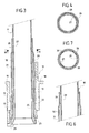
- the radially outside of the sampling tube 11 accommodates inside a tube external damper 20.
- This external tube 20 has at its end radially internal a rectangular base 21 which bears against the internal face of the core 14 of the ring and at least partially covers the rectangular openings 16.
- the radially outer part 22 of the tube outer 20 has an outer diameter substantially equal to that of the holes 15 formed in the core 14 of the ring 10, so that this part 22 can be inserted tightly into a hole 15.
- the bases 21 form together a ring which closes the rectangular openings 16.
- the sampling tube 11 has in its portion radially exterior a bead 23 which bears against the radially end inner of the outer tube 20.
- This bead 23 extends inside of the radially inner part 22 of the outer tube 20 by a collar 24 of which the outside diameter is substantially equal to the outside diameter of the part 22 so that the collar 24 is tightened in this part 22.
- the reference 25 denotes a locking ring for the outer tube 20 and the tube sampling 11 on the ring 10.
- This locking ring 25 has a section in inverted T, whose wings press on the end faces radially inside the front radial wall 12 of the ring 10 and the sampling tube 11, and the core of which is housed between the rear face of the wall front radial 12 and the beads 23 of the sampling tubes 11.
- the wings of this ring 25 can be differentiated in length as well as radially to ensure predictable mounting, i.e. always in the same way.
- the radially outer end 26 of the outer tube 20 is in contact with the corresponding zone 27 of the sampling tube 11.
- the end 26 is constricted and has a plurality of axial zones 28 in tight contact against the outer wall of zone 27.
- These zones axial 28 are produced for example by clamping the end 26 of the outer tube 20 by means of jaws.
- Figure 4 shows four areas axially 28 diametrically opposite two by two, but the number of axial zones 28 can be different from four.
- Figures 6 and 7 show a second embodiment of the contact between the end 26 of the outer tube 20 and the area 27 of the sampling 11.
- zone 27 has a collar 29 having a plurality of plates 30.
- the external diameter of the collar 29 is substantially equal to the inside diameter of the end 26 of the outer tube 20, so to ensure a positive contact between the two tubes 20 and 11 at the level of the collar 29.
- the central zone 31 of the outer tube 20 is out of contact with the tube sample 11, and is separated from the latter by an annular chamber 32.
- the sampling tube 11 is tightly retained by its radially outer end in the outer tube 20 and is retained with some flexibility by the radially inner end 26 of the outer tube 20.
- the outer tube 20 acts at this location in the manner of a spring and the stiffness at this contact dissipates energy like a spring.
- the tube external 20 Due to the presence of the annular chamber 32, the tube external 20 is also subjected to vibratory bending torques.
- the stiffness in bending of the outer tube 20 also allows dissipation of Energy. Due to the increase in the equivalent stiffness of the assembly of the two tubes 20 and 11, with respect to the state of the art unveiled by US 5,472,313, the frequency of the first bending mode, says 1F mode, is greatly increased.
Landscapes
- Engineering & Computer Science (AREA)
- Mechanical Engineering (AREA)
- General Engineering & Computer Science (AREA)
- Physics & Mathematics (AREA)
- Thermal Sciences (AREA)
- Structures Of Non-Positive Displacement Pumps (AREA)
- Heat-Exchange Devices With Radiators And Conduit Assemblies (AREA)
Abstract
Description
Claims (4)
- Dispositif de prélèvement d'air par écoulement centripète prévu entre deux disques (3a, 3b) d'un compresseur (1) de turbomachine, ledit dispositif comportant un support annulaire (10) fixé sur une face de l'un desdits disques (3a, 3b) et une pluralité de tubes de prélèvement (11) d'air montés sensiblement radialement dans des orifices (15) ménagés dans ledit support (10), chaque tube (11) étant équipé de moyens pour réduire les vibrations dudit tube (11) lors du fonctionnement de la turbomachine,
caractérisé par le fait que les moyens pour réduire les vibrations d'un tube de prélèvement (11) comportent un tube amortisseur (20) retenu dans un orifice (15) du support annulaire (10) et entourant la partie radialement extérieure dudit tube de prélèvement (11), l'extrémité radialement intérieure (26) dudit tube amortisseur (20) enserrant une zone correspondante 27 dudit tube de prélèvement (11) et un espace annulaire (32) étant prévu entre la zone médiane (31) dudit tube amortisseur (20) et ledit tube de prélèvement (11). - Dispositif selon la revendication 1, caractérisé par le fait que l'extrémité radialement intérieure (26) du tube amortisseur (20) est rétreinte et est en contact avec la paroi périphérique du tube de prélèvement (11) selon une pluralité de zones axiales (28).
- Dispositif selon la revendication 1, caractérisé par le fait que le tube de prélèvement (11) présente au droit de l'extrémité radialement intérieure (26) du tube amortisseur (20), un collet (29) s'adaptant dans ladite extrémité (26).
- Dispositif selon la revendication 3, caractérisé par le fait que le collet (29) comporte une pluralité de plats (30).
Applications Claiming Priority (2)
| Application Number | Priority Date | Filing Date | Title |
|---|---|---|---|
| FR0107121A FR2825413B1 (fr) | 2001-05-31 | 2001-05-31 | Dispositif de prelevement d'air par ecoulement centripete |
| FR0107121 | 2001-05-31 |
Publications (2)
| Publication Number | Publication Date |
|---|---|
| EP1262630A1 true EP1262630A1 (fr) | 2002-12-04 |
| EP1262630B1 EP1262630B1 (fr) | 2005-04-06 |
Family
ID=8863805
Family Applications (1)
| Application Number | Title | Priority Date | Filing Date |
|---|---|---|---|
| EP02291314A Expired - Lifetime EP1262630B1 (fr) | 2001-05-31 | 2002-05-30 | Dispositif de prélèvement d'air par écoulement centripète |
Country Status (9)
| Country | Link |
|---|---|
| US (1) | US6648592B2 (fr) |
| EP (1) | EP1262630B1 (fr) |
| JP (1) | JP4071997B2 (fr) |
| CA (1) | CA2387462C (fr) |
| DE (1) | DE60203563T2 (fr) |
| ES (1) | ES2236459T3 (fr) |
| FR (1) | FR2825413B1 (fr) |
| RU (1) | RU2224124C1 (fr) |
| UA (1) | UA68458C2 (fr) |
Cited By (5)
| Publication number | Priority date | Publication date | Assignee | Title |
|---|---|---|---|---|
| FR2930589A1 (fr) * | 2008-04-24 | 2009-10-30 | Snecma Sa | Prelevement d'air centripete dans un rotor de compresseur d'une turbomachine |
| EP2410136A3 (fr) * | 2010-07-22 | 2014-09-24 | United Technologies Corporation | Dispositif pour la réduction des tourbillons dans une turbine à gaz |
| EP2612988A3 (fr) * | 2012-01-04 | 2017-12-27 | General Electric Company | Ensemble de tuyaux de compresseur |
| FR3073559A1 (fr) * | 2017-11-14 | 2019-05-17 | Safran Aircraft Engines | Ensemble de rotor comprenant un disque de rotor supportant un organe de prelevement d'air centripete |
| WO2019214915A1 (fr) | 2018-05-09 | 2019-11-14 | Safran Aircraft Engines | Turbomachine comportant un circuit de prelevement d'air |
Families Citing this family (32)
| Publication number | Priority date | Publication date | Assignee | Title |
|---|---|---|---|---|
| DE10159670A1 (de) * | 2001-12-05 | 2003-06-18 | Rolls Royce Deutschland | Wirbelgleichrichter im Hochdruckverdichter einer Gasturbine |
| DE10310815A1 (de) * | 2003-03-12 | 2004-09-23 | Rolls-Royce Deutschland Ltd & Co Kg | Wirbelgleichrichter in Röhrenbauweise mit Haltering |
| US7296957B2 (en) * | 2004-05-06 | 2007-11-20 | General Electric Company | Methods and apparatus for coupling gas turbine engine components |
| DE102004042295A1 (de) * | 2004-09-01 | 2006-03-02 | Mtu Aero Engines Gmbh | Rotor für ein Triebwerk |
| US7448221B2 (en) * | 2004-12-17 | 2008-11-11 | United Technologies Corporation | Turbine engine rotor stack |
| FR2889565B1 (fr) * | 2005-08-03 | 2012-05-18 | Snecma | Compresseur a prelevement d'air centripete |
| US7344354B2 (en) * | 2005-09-08 | 2008-03-18 | General Electric Company | Methods and apparatus for operating gas turbine engines |
| US7278322B1 (en) * | 2006-03-30 | 2007-10-09 | International Business Machines Corporation | Semiconductor based pressure sensor |
| DE102008024146A1 (de) * | 2008-05-19 | 2009-11-26 | Rolls-Royce Deutschland Ltd & Co Kg | Kombinierter Wirbelgleichrichter |
| DE102008029528A1 (de) | 2008-06-21 | 2009-12-24 | Mtu Aero Engines Gmbh | Vorrichtung zur Gasführung zwischen Rotorscheiben eines Verdichters |
| US8459078B2 (en) * | 2009-10-15 | 2013-06-11 | New Jersey Institute Of Technology | System and method for forming of tubular parts |
| US8662845B2 (en) | 2011-01-11 | 2014-03-04 | United Technologies Corporation | Multi-function heat shield for a gas turbine engine |
| US8840375B2 (en) | 2011-03-21 | 2014-09-23 | United Technologies Corporation | Component lock for a gas turbine engine |
| US8915057B2 (en) * | 2012-02-10 | 2014-12-23 | General Electric Company | Gas turbine engine sump pressurization system |
| US9371736B2 (en) * | 2012-05-23 | 2016-06-21 | Solar Turbines Incorporated | Method and device for modifying a secondary air system in a gas turbine engine |
| CA2931500A1 (fr) * | 2013-11-26 | 2015-06-04 | General Electric Company | Ensemble de dechargement pour rotor |
| FR3016936B1 (fr) | 2014-01-24 | 2019-05-17 | Safran Aircraft Engines | Disque de rotor a dispositif de prelevement d'air centripete, compresseur comportant ledit disque et turbomachine avec un tel compresseur |
| FR3024179B1 (fr) * | 2014-07-25 | 2016-08-26 | Snecma | Systeme d'alimentation en air sous pression installe dans une turbomachine d'aeronef comportant des moyens d'etancheite |
| DE102015216110A1 (de) | 2015-08-24 | 2017-03-02 | Rolls-Royce Deutschland Ltd & Co Kg | Verdichter und Verfahren zur Montage eines Verdichters |
| CN105114357A (zh) * | 2015-09-17 | 2015-12-02 | 中国航空工业集团公司沈阳发动机设计研究所 | 一种压气机转子引气结构 |
| US10968771B2 (en) | 2017-01-12 | 2021-04-06 | General Electric Company | Method and system for ice tolerant bleed takeoff |
| CN107023394B (zh) * | 2017-04-07 | 2019-03-22 | 中国航发沈阳发动机研究所 | 带阻尼的管式压气机转子引气装置 |
| RU189794U1 (ru) * | 2017-08-29 | 2019-06-04 | Акционерное общество "Объединенная двигателестроительная корпорация" (АО "ОДК") | Ротор компрессора газотурбинного двигателя |
| FR3073581B1 (fr) * | 2017-11-14 | 2019-11-22 | Safran Aircraft Engines | Dispositif de maintien d'un organe de prelevement d'air radial centripete |
| US10808627B2 (en) * | 2018-03-26 | 2020-10-20 | Raytheon Technologies Corporation | Double bore basket |
| US11136896B2 (en) | 2019-04-24 | 2021-10-05 | Raytheon Technologies Corporation | Rotating leaf spring seal |
| US11371351B2 (en) | 2020-01-17 | 2022-06-28 | Raytheon Technologies Corporation | Multi-disk bladed rotor assembly for rotational equipment |
| US11339673B2 (en) * | 2020-01-17 | 2022-05-24 | Raytheon Technologies Corporation | Rotor assembly with internal vanes |
| CN114542641B (zh) * | 2020-11-24 | 2024-04-05 | 中国航发商用航空发动机有限责任公司 | 阻尼减振装置以及航空发动机 |
| CN114542640B (zh) * | 2020-11-24 | 2024-04-05 | 中国航发商用航空发动机有限责任公司 | 阻尼减振装置以及航空发动机 |
| CN114776927B (zh) * | 2022-04-16 | 2024-04-09 | 中国航发沈阳发动机研究所 | 一种航空发动机引气管阻尼减振结构 |
| CN115493018A (zh) * | 2022-11-21 | 2022-12-20 | 中国航发四川燃气涡轮研究院 | 一种用于航空发动机管式减涡器引气管的减振结构 |
Citations (5)
| Publication number | Priority date | Publication date | Assignee | Title |
|---|---|---|---|---|
| US4415310A (en) * | 1980-10-08 | 1983-11-15 | Societe Nationale D'etude Et De Construction De Moteurs D'aviation, "S.N.E.C.M.A." | System for cooling a gas turbine by bleeding air from the compressor |
| US4595339A (en) * | 1983-09-21 | 1986-06-17 | Societe Nationale D'etude Et De Construction De Meteurs D'aviation S.N.E.C.M.A. | Centripetal accelerator for air exhaustion in a cooling device of a gas turbine combined with the compressor disc |
| US4787820A (en) * | 1987-01-14 | 1988-11-29 | Societe Nationale D'etude Et De Construction De Moteurs D'aviation "S.N.E.C.M.A." | Turbine plant compressor disc with centripetal accelerator for the induction of turbine cooling air |
| FR2672943A1 (fr) * | 1991-02-20 | 1992-08-21 | Snecma | Compresseur de turbomachine equipe d'un dispositif de prelevement d'air. |
| US5472313A (en) * | 1991-10-30 | 1995-12-05 | General Electric Company | Turbine disk cooling system |
Family Cites Families (8)
| Publication number | Priority date | Publication date | Assignee | Title |
|---|---|---|---|---|
| DE1070880B (de) * | 1956-12-19 | 1959-12-10 | Rolls-Royce Limited, Derby (Großbritannien) | Gasturbinenaggregat mit Turboverdichter |
| US3844110A (en) * | 1973-02-26 | 1974-10-29 | Gen Electric | Gas turbine engine internal lubricant sump venting and pressurization system |
| DE2410139C3 (de) * | 1974-03-02 | 1981-10-15 | Klöckner-Humboldt-Deutz AG, 5000 Köln | Gasturbinenanlage |
| GB2048380B (en) * | 1979-05-08 | 1983-06-15 | Avco Corp | Gas trubine air bleed |
| SU1326783A1 (ru) * | 1986-03-26 | 1987-07-30 | И. К. Попов | Устройство дл демпфировани колебаний лопатки осевого компрессора |
| SU1475256A1 (ru) * | 1987-03-27 | 1999-07-27 | А.А. Кохан | Судовая газотурбинная установка |
| US4815272A (en) * | 1987-05-05 | 1989-03-28 | United Technologies Corporation | Turbine cooling and thermal control |
| US5267832A (en) * | 1992-03-30 | 1993-12-07 | United Technologies Corporation | Flarable retainer |
-
2001
- 2001-05-31 FR FR0107121A patent/FR2825413B1/fr not_active Expired - Fee Related
-
2002
- 2002-05-24 CA CA002387462A patent/CA2387462C/fr not_active Expired - Fee Related
- 2002-05-30 ES ES02291314T patent/ES2236459T3/es not_active Expired - Lifetime
- 2002-05-30 RU RU2002114272/06A patent/RU2224124C1/ru not_active IP Right Cessation
- 2002-05-30 DE DE60203563T patent/DE60203563T2/de not_active Expired - Lifetime
- 2002-05-30 EP EP02291314A patent/EP1262630B1/fr not_active Expired - Lifetime
- 2002-05-30 UA UA2002054446A patent/UA68458C2/uk unknown
- 2002-05-30 JP JP2002156787A patent/JP4071997B2/ja not_active Expired - Fee Related
- 2002-05-31 US US10/157,887 patent/US6648592B2/en not_active Expired - Lifetime
Patent Citations (5)
| Publication number | Priority date | Publication date | Assignee | Title |
|---|---|---|---|---|
| US4415310A (en) * | 1980-10-08 | 1983-11-15 | Societe Nationale D'etude Et De Construction De Moteurs D'aviation, "S.N.E.C.M.A." | System for cooling a gas turbine by bleeding air from the compressor |
| US4595339A (en) * | 1983-09-21 | 1986-06-17 | Societe Nationale D'etude Et De Construction De Meteurs D'aviation S.N.E.C.M.A. | Centripetal accelerator for air exhaustion in a cooling device of a gas turbine combined with the compressor disc |
| US4787820A (en) * | 1987-01-14 | 1988-11-29 | Societe Nationale D'etude Et De Construction De Moteurs D'aviation "S.N.E.C.M.A." | Turbine plant compressor disc with centripetal accelerator for the induction of turbine cooling air |
| FR2672943A1 (fr) * | 1991-02-20 | 1992-08-21 | Snecma | Compresseur de turbomachine equipe d'un dispositif de prelevement d'air. |
| US5472313A (en) * | 1991-10-30 | 1995-12-05 | General Electric Company | Turbine disk cooling system |
Cited By (9)
| Publication number | Priority date | Publication date | Assignee | Title |
|---|---|---|---|---|
| FR2930589A1 (fr) * | 2008-04-24 | 2009-10-30 | Snecma Sa | Prelevement d'air centripete dans un rotor de compresseur d'une turbomachine |
| EP2410136A3 (fr) * | 2010-07-22 | 2014-09-24 | United Technologies Corporation | Dispositif pour la réduction des tourbillons dans une turbine à gaz |
| EP2612988A3 (fr) * | 2012-01-04 | 2017-12-27 | General Electric Company | Ensemble de tuyaux de compresseur |
| FR3073559A1 (fr) * | 2017-11-14 | 2019-05-17 | Safran Aircraft Engines | Ensemble de rotor comprenant un disque de rotor supportant un organe de prelevement d'air centripete |
| WO2019214915A1 (fr) | 2018-05-09 | 2019-11-14 | Safran Aircraft Engines | Turbomachine comportant un circuit de prelevement d'air |
| FR3081027A1 (fr) * | 2018-05-09 | 2019-11-15 | Safran Aircraft Engines | Turbomachine comportant un circuit de prelevement d'air |
| CN112088252A (zh) * | 2018-05-09 | 2020-12-15 | 赛峰飞机发动机公司 | 一种涡轮机和收集涡轮机中的气流的方法 |
| US11105262B2 (en) | 2018-05-09 | 2021-08-31 | Safran Aircraft Engines | Turbomachine comprising an air collection circuit |
| CN112088252B (zh) * | 2018-05-09 | 2022-08-02 | 赛峰飞机发动机公司 | 一种涡轮机和收集涡轮机中的气流的方法 |
Also Published As
| Publication number | Publication date |
|---|---|
| FR2825413A1 (fr) | 2002-12-06 |
| EP1262630B1 (fr) | 2005-04-06 |
| JP2003035165A (ja) | 2003-02-07 |
| JP4071997B2 (ja) | 2008-04-02 |
| UA68458C2 (en) | 2004-08-16 |
| CA2387462C (fr) | 2009-11-24 |
| RU2224124C1 (ru) | 2004-02-20 |
| US6648592B2 (en) | 2003-11-18 |
| DE60203563T2 (de) | 2006-02-09 |
| ES2236459T3 (es) | 2005-07-16 |
| CA2387462A1 (fr) | 2002-11-30 |
| US20020182059A1 (en) | 2002-12-05 |
| DE60203563D1 (de) | 2005-05-12 |
| FR2825413B1 (fr) | 2003-09-05 |
Similar Documents
| Publication | Publication Date | Title |
|---|---|---|
| EP1262630B1 (fr) | Dispositif de prélèvement d'air par écoulement centripète | |
| EP1498624B1 (fr) | Dispositif perfectionné de fixation d'un arbre de moteur sur un support de palier | |
| EP2028375B1 (fr) | Soufflante pour turbomachine d'aéronef comprenant une bride d'équilibrage masquée par le cône d'entrée | |
| CA2607238C (fr) | Systeme d'equilibrage pour rotor de turbomachine | |
| EP1918512B1 (fr) | Système d'équilibrage pour rotor de turbomachine | |
| EP3074638B1 (fr) | Soufflante pour une turbomachine | |
| CA2787480C (fr) | Liaison diffuseur-redresseur pour un compresseur centrifuge | |
| EP1213484A1 (fr) | Etage redressseur d'un compresseur | |
| CA2625319A1 (fr) | Soufflante de turbomachine | |
| FR2918109A1 (fr) | Roue mobile pour un turboreacteur et turboreacteur la comportant | |
| CA2598532C (fr) | Aube de rotor d'une turbomachine | |
| FR2574478A1 (fr) | Ameliorations apportees a un moteur a turbine a gaz | |
| WO2015110751A1 (fr) | Disque de rotor a dispositif de prélèvement d'air centripète, compresseur comportant ledit disque et turbomachine avec un tel compresseur | |
| FR2971022A1 (fr) | Etage redresseur de compresseur pour une turbomachine | |
| EP1213483A1 (fr) | Etage redresseur d'un compresseur | |
| EP1598524A1 (fr) | Procédé d'assemblage de disques aubagés monoblocs et dispositif d'amortissement des vibrations des aubes de ces disques | |
| FR2978798A1 (fr) | Secteur angulaire de redresseur de turbomachine a amortissement des modes de vibrations | |
| FR2958322A1 (fr) | Rotor de moteur a turbine a gaz comprenant un tambour de rotor et une couronne de rotor | |
| FR2888876A1 (fr) | Dispositif d'amortissement des vibrations d'un rotor dans une turbomachine | |
| EP4396445B1 (fr) | Dispositif d'amortissement pour roue mobile de turbomachine d'aéronef, roue mobile pour turbomachine d'aéronef, turbomachine pour aéronef et procédé de fabrication d'un dispositif d'amortissement | |
| FR2907496A1 (fr) | Disque de rotor de turbomachine et module de turbomachine comprenant un tel disque | |
| FR2888877A1 (fr) | Dispositif d'amortissement des vibrations d'un rotor | |
| EP2631490B1 (fr) | Roue à aubes radiale avec couronne de base radialement libre | |
| FR2486603A1 (fr) | Dispositif d'embrayage a friction | |
| EP1134361B1 (fr) | Turbomachine comportant un dispositif de suppression des vibrations |
Legal Events
| Date | Code | Title | Description |
|---|---|---|---|
| PUAI | Public reference made under article 153(3) epc to a published international application that has entered the european phase |
Free format text: ORIGINAL CODE: 0009012 |
|
| 17P | Request for examination filed |
Effective date: 20020607 |
|
| AK | Designated contracting states |
Kind code of ref document: A1 Designated state(s): AT BE CH CY DE DK ES FI FR GB GR IE IT LI LU MC NL PT SE TR |
|
| AX | Request for extension of the european patent |
Free format text: AL;LT;LV;MK;RO;SI |
|
| AKX | Designation fees paid |
Designated state(s): DE ES FR GB IT SE |
|
| GRAP | Despatch of communication of intention to grant a patent |
Free format text: ORIGINAL CODE: EPIDOSNIGR1 |
|
| GRAS | Grant fee paid |
Free format text: ORIGINAL CODE: EPIDOSNIGR3 |
|
| GRAA | (expected) grant |
Free format text: ORIGINAL CODE: 0009210 |
|
| AK | Designated contracting states |
Kind code of ref document: B1 Designated state(s): DE ES FR GB IT SE |
|
| REG | Reference to a national code |
Ref country code: GB Ref legal event code: FG4D Free format text: NOT ENGLISH |
|
| GBT | Gb: translation of ep patent filed (gb section 77(6)(a)/1977) |
Effective date: 20050406 |
|
| REG | Reference to a national code |
Ref country code: IE Ref legal event code: FG4D Free format text: LANGUAGE OF EP DOCUMENT: FRENCH |
|
| REF | Corresponds to: |
Ref document number: 60203563 Country of ref document: DE Date of ref document: 20050512 Kind code of ref document: P |
|
| REG | Reference to a national code |
Ref country code: ES Ref legal event code: FG2A Ref document number: 2236459 Country of ref document: ES Kind code of ref document: T3 |
|
| REG | Reference to a national code |
Ref country code: SE Ref legal event code: TRGR |
|
| RAP2 | Party data changed (patent owner data changed or rights of a patent transferred) |
Owner name: SNECMA |
|
| PLBE | No opposition filed within time limit |
Free format text: ORIGINAL CODE: 0009261 |
|
| STAA | Information on the status of an ep patent application or granted ep patent |
Free format text: STATUS: NO OPPOSITION FILED WITHIN TIME LIMIT |
|
| 26N | No opposition filed |
Effective date: 20060110 |
|
| REG | Reference to a national code |
Ref country code: FR Ref legal event code: CD |
|
| PGFP | Annual fee paid to national office [announced via postgrant information from national office to epo] |
Ref country code: ES Payment date: 20120508 Year of fee payment: 11 |
|
| REG | Reference to a national code |
Ref country code: ES Ref legal event code: FD2A Effective date: 20140606 |
|
| PG25 | Lapsed in a contracting state [announced via postgrant information from national office to epo] |
Ref country code: ES Free format text: LAPSE BECAUSE OF NON-PAYMENT OF DUE FEES Effective date: 20130531 |
|
| PGFP | Annual fee paid to national office [announced via postgrant information from national office to epo] |
Ref country code: SE Payment date: 20140425 Year of fee payment: 13 Ref country code: DE Payment date: 20140424 Year of fee payment: 13 Ref country code: IT Payment date: 20140424 Year of fee payment: 13 |
|
| REG | Reference to a national code |
Ref country code: FR Ref legal event code: PLFP Year of fee payment: 14 |
|
| REG | Reference to a national code |
Ref country code: DE Ref legal event code: R119 Ref document number: 60203563 Country of ref document: DE |
|
| PG25 | Lapsed in a contracting state [announced via postgrant information from national office to epo] |
Ref country code: IT Free format text: LAPSE BECAUSE OF NON-PAYMENT OF DUE FEES Effective date: 20150530 |
|
| PG25 | Lapsed in a contracting state [announced via postgrant information from national office to epo] |
Ref country code: SE Free format text: LAPSE BECAUSE OF NON-PAYMENT OF DUE FEES Effective date: 20150531 |
|
| PG25 | Lapsed in a contracting state [announced via postgrant information from national office to epo] |
Ref country code: DE Free format text: LAPSE BECAUSE OF NON-PAYMENT OF DUE FEES Effective date: 20151201 |
|
| REG | Reference to a national code |
Ref country code: FR Ref legal event code: PLFP Year of fee payment: 15 |
|
| REG | Reference to a national code |
Ref country code: FR Ref legal event code: PLFP Year of fee payment: 16 |
|
| REG | Reference to a national code |
Ref country code: FR Ref legal event code: CD Owner name: SNECMA, FR Effective date: 20170713 |
|
| REG | Reference to a national code |
Ref country code: FR Ref legal event code: PLFP Year of fee payment: 17 |
|
| PGFP | Annual fee paid to national office [announced via postgrant information from national office to epo] |
Ref country code: FR Payment date: 20210421 Year of fee payment: 20 |
|
| PGFP | Annual fee paid to national office [announced via postgrant information from national office to epo] |
Ref country code: GB Payment date: 20210422 Year of fee payment: 20 |
|
| REG | Reference to a national code |
Ref country code: GB Ref legal event code: PE20 Expiry date: 20220529 |
|
| PG25 | Lapsed in a contracting state [announced via postgrant information from national office to epo] |
Ref country code: GB Free format text: LAPSE BECAUSE OF EXPIRATION OF PROTECTION Effective date: 20220529 |