EP1262309A2 - Mould and method for moulding a foamed filling for a tire - Google Patents
Mould and method for moulding a foamed filling for a tire Download PDFInfo
- Publication number
- EP1262309A2 EP1262309A2 EP02011608A EP02011608A EP1262309A2 EP 1262309 A2 EP1262309 A2 EP 1262309A2 EP 02011608 A EP02011608 A EP 02011608A EP 02011608 A EP02011608 A EP 02011608A EP 1262309 A2 EP1262309 A2 EP 1262309A2
- Authority
- EP
- European Patent Office
- Prior art keywords
- mold
- joining faces
- joining
- concave portion
- faces
- Prior art date
- Legal status (The legal status is an assumption and is not a legal conclusion. Google has not performed a legal analysis and makes no representation as to the accuracy of the status listed.)
- Granted
Links
Images






Classifications
-
- B—PERFORMING OPERATIONS; TRANSPORTING
- B29—WORKING OF PLASTICS; WORKING OF SUBSTANCES IN A PLASTIC STATE IN GENERAL
- B29C—SHAPING OR JOINING OF PLASTICS; SHAPING OF MATERIAL IN A PLASTIC STATE, NOT OTHERWISE PROVIDED FOR; AFTER-TREATMENT OF THE SHAPED PRODUCTS, e.g. REPAIRING
- B29C44/00—Shaping by internal pressure generated in the material, e.g. swelling or foaming ; Producing porous or cellular expanded plastics articles
- B29C44/02—Shaping by internal pressure generated in the material, e.g. swelling or foaming ; Producing porous or cellular expanded plastics articles for articles of definite length, i.e. discrete articles
- B29C44/027—Shaping by internal pressure generated in the material, e.g. swelling or foaming ; Producing porous or cellular expanded plastics articles for articles of definite length, i.e. discrete articles the foaming continuing or beginning when the mould is opened
-
- B—PERFORMING OPERATIONS; TRANSPORTING
- B29—WORKING OF PLASTICS; WORKING OF SUBSTANCES IN A PLASTIC STATE IN GENERAL
- B29C—SHAPING OR JOINING OF PLASTICS; SHAPING OF MATERIAL IN A PLASTIC STATE, NOT OTHERWISE PROVIDED FOR; AFTER-TREATMENT OF THE SHAPED PRODUCTS, e.g. REPAIRING
- B29C33/00—Moulds or cores; Details thereof or accessories therefor
- B29C33/30—Mounting, exchanging or centering
- B29C33/303—Mounting, exchanging or centering centering mould parts or halves, e.g. during mounting
-
- B—PERFORMING OPERATIONS; TRANSPORTING
- B29—WORKING OF PLASTICS; WORKING OF SUBSTANCES IN A PLASTIC STATE IN GENERAL
- B29C—SHAPING OR JOINING OF PLASTICS; SHAPING OF MATERIAL IN A PLASTIC STATE, NOT OTHERWISE PROVIDED FOR; AFTER-TREATMENT OF THE SHAPED PRODUCTS, e.g. REPAIRING
- B29C44/00—Shaping by internal pressure generated in the material, e.g. swelling or foaming ; Producing porous or cellular expanded plastics articles
- B29C44/34—Auxiliary operations
- B29C44/58—Moulds
-
- B—PERFORMING OPERATIONS; TRANSPORTING
- B29—WORKING OF PLASTICS; WORKING OF SUBSTANCES IN A PLASTIC STATE IN GENERAL
- B29D—PRODUCING PARTICULAR ARTICLES FROM PLASTICS OR FROM SUBSTANCES IN A PLASTIC STATE
- B29D30/00—Producing pneumatic or solid tyres or parts thereof
- B29D30/04—Resilient fillings for rubber tyres; Filling tyres therewith
Definitions
- the present invention relates to a mold for molding a foamed tube for a tire which is used in place of a hollow rubber tube of a pneumatic tire, and to a method of manufacturing a foamed tube for a tire.
- a joining face 103A of the upper die 102A and a joining face 103B of the lower die 102B are both horizontal.
- the foamed tube for a tire which is obtained in this way is cooled naturally at room temperature, and is kept until the foaming rate decreases and is stable.
- a foamed tube for a tire whose dimensions have stabilized is then served for use (i.e., actually mounted to a motorcycle or the like).
- the gas generated in the rubber becomes air bubbles and expands.
- the rubber composition suddenly expands (the volume thereof suddenly increases to about 500 to 1200%) substantially simultaneously with the opening of the mold 102.
- the swelled rubber composition enters into the narrow gap between the joining faces of the upper die 102A and the lower die 102B which are opened slightly, and bursts out to the exterior of the mold 102.
- tears 104, 106 arise in the surface of the rubber composition which has burst out and swelled.
- a problem arises in that there are many cases in which the tears 104, 106 remain in the foamed tube for a tire (the donut-shaped torus 14) which is finally obtained.
- the speed of opening the vulcanizing press to which the mold 102 is mounted is made to be extremely fast in order to handle the expanding of the rubber composition, or the joining face 103A and the joining face 103B of the upper die 102A and the lower die 102B are made to be extremely wide so as to suppress the bursting out of the rubber composition to the exterior of the mold, or the foaming rate is set to be low to the extent that tears do not arise, or the blending composition of the rubber composition is adjusted so as to make the modulus high.
- the properties of the rubber composition have to be restricted, and there are cases in which desired product properties cannot be obtained.
- an object of the present invention is to provide a mold for molding a foamed tube for a tire and a method of manufacturing a foamed tube for a tire which can overcome the above-described problems of the conventional art.
- a first aspect of the present invention is a mold for molding an annular foamed tube for a tire, comprising: a first mold having a first annular concave portion which molds one side, in an axial direction, of the foamed tube for a tire; and a second mold having a second annular concave portion which molds another side, in the axial direction, of the foamed tube for a tire, wherein when the first mold and the second mold are combined in the axial direction, the first annular concave portion and the second annular concave portion form an annular space for molding the foamed tube for a tire, the first mold has first joining faces which are connected to the first annular concave portion and which are positioned at an inner side and an outer side, in a radial direction, of the first annular concave portion, and the first joining faces include horizontal joining faces provided adjacent to the first annular concave portion in a direction orthogonal to the axial direction at the inner side and the outer side
- the foaming-agent-containing rubber composition which is formed in a toroidal configuration, is positioned in the first annular concave portion (or the second annular concave portion) of the mold which has been preheated, and the first mold and the second mold are closed.
- the molds are heated by a heater, and vulcanization of the rubber composition is carried out.
- the molds After heating has been carried out for a predetermined period of time, the molds are opened, and the rubber composition is removed.
- each of the joining faces of the first mold and the joining faces of the second mold has horizontal joining faces provided adjacent to the annular concave portion in a direction orthogonal to an axial direction at an inner side and an outer side, in the radial direction, of the annular concave portion, and an inclined joining face provided continuously with each horizontal joining face so as to be inclined with respect to the horizontal joining face at one of an inner side and an outer side in the radial direction. Accordingly, in the initial stages of opening the two molds which have been combined, the gap between the inclined joining faces of the first mold and the inclined joining faces of the second mold remains extremely small as compared with the dimension by which the first mold and the second mold are separated.
- the rubber composition When the molds are opened immediately after vulcanization molding of the rubber composition has been completed, substantially simultaneously, the rubber composition swells rapidly, and first, the rubber composition enters into a gap between the horizontal joining faces of the first mold and the horizontal joining faces of the second mold. The foamed rubber composition which has entered into the gap between the horizontal joining face portions abuts the inclined joining faces at the outer sides and stops.
- the gap between the inclined joining face portions remains extremely narrow. Further, the direction of the gap between these inclined joining face portions is much different than the direction of swelling of the rubber composition which has entered into the gap between the horizontal joining face portions. Moreover, as the mold is opened, even if the gap between the horizontal joining faces becomes large, the size of the swelling rubber composition at the gap between the horizontal joining face portions simultaneously becomes large. Accordingly, the force of the swelling rubber composition entering into the gap between the inclined joining faces is small.
- the swelled, foamed rubber composition is pushed by its own swelling force against the inclined joining faces, and sliding resistance is generated.
- the foamed rubber composition does not move within the molds. Namely, until the molds are completely opened, the swelled, foamed rubber composition does not protrude out to the exterior of the molds from the gap between the inclined joining faces.
- the molds are then completely opened, and the foamed, toroidal rubber composition is removed therefrom and left at room temperature until the foaming rate is stabilized.
- the production of the foamed tube for a tire is thereby completed.
- At least the inclined joining faces which are positioned at the outer side in the radial direction form an angle of 90 to 120° with respect to the horizontal joining face adjacent thereto.
- the angle of the inclined joining face positioned at the outer side in the radial direction, with respect to the horizontal joining face adjacent thereto, is 120° or more, the outer shape of the mold becomes too large, which is not effective.
- the angle of the inclined joining face with respect to the horizontal inclined surface is less than 90°, it is not possible to open and close the first mold and the second mold unless at least one of the first mold and the second mold is divided into plural pieces.
- the angle between the inclined joining face and the horizontal joining face of the first mold and the angle between the inclined joining face and the horizontal joining face of the second mold are different, opening and closing of the first mold and the second mold are possible.
- the inclined joining face positioned at the outer side in the radial direction is 90° or less with respect to the horizontal joining face, the foamed rubber composition catches on the mold and removal thereof will be difficult.
- angle of the inclined joining face positioned at the outer side in the radial direction, with respect to the horizontal joining face adjacent thereto is preferably 93 to 105°.
- a cross-sectional configuration, along the axial direction, of the annular space is circular, and given that a radius of the annular space is R and a projected length, in the axial direction, of the inclined joining face is H, a relation R ⁇ H ⁇ 3R is satisfied.
- the cross-sectional configuration of the annular space is a configuration other than circular (e.g., is oval)
- a fourth aspect of the present invention is a method of manufacturing a foamed tube for a tire, comprising the steps of: (a) filling a foaming-agent-containing rubber composition, which generates gas when heated, into at least the annular space of the mold recited in claim 1; and (b) heating and vulcanizing the foaming-agent-containing rubber composition.
- the method of manufacturing a foamed tube for a tire based on the above-described fourth aspect has the same contents as the operation of the first aspect, and therefore, description thereof will be omitted.
- Fig. 1A is a side view showing a vicinity of a cut surface of an elongated extruded rubber composition used in the device and method of the present invention
- Fig. 1B is a side view showing a joined portion of the elongated extruded rubber composition of Fig. 1A.
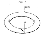
- Fig. 2 is a perspective view of a donut-shaped torus in which the elongated extruded rubber composition is joined.
- Fig. 3A is a cross-sectional view of a mold of the present invention in an open state
- Fig. 3B is a cross-sectional view of the mold of the present invention in a closed state.
- Fig. 4 is a partial, enlarged cross-sectional view of the mold which is closed.
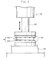
- Fig. 5 is a front view of main portions of a press machine to which the mold is mounted.
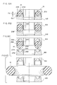
- Figs. 6A through 6D are explanatory diagrams showing processes of opening the mold.
- Fig. 7 is a perspective view of a foamed tube for a tire which is manufactured on the basis of the present invention.
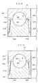
- Fig. 8 is a partial, enlarged cross-sectional view of a mold relating to another embodiment.
- Fig. 9 is a partial, enlarged cross-sectional view of a mold relating to yet another embodiment.
- Fig. 10 is a partial, enlarged cross-sectional view of a mold relating to still another embodiment.
- Fig. 11 is a partial, enlarged cross-sectional view of a mold relating to still yet another embodiment.
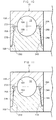
- Fig. 12A is a cross-sectional view of a conventional mold in an open state
- Fig. 12B is a cross-sectional view of the conventional mold in a closed state.
- Fig. 13 is a cross-sectional view of the conventional mold in a state of being opened slightly.
- Fig. 14 is a cross-sectional view of the conventional mold, and a foamed tube for a tire which is manufactured by the mold and in which tears have arisen.
- a rubber composition containing a foaming agent is extruded from the die of an extruder, which die has a circular opening, so as to obtain an elongated extruded rubber composition whose cross-sectional configuration orthogonal to the longitudinal direction thereof is circular.
- the extruder it is possible to continuously obtain a homogeneous elongated extruded rubber composition whose cross-sectional configuration is constant and whose dimensions are constant.
- the rubber composition containing a foaming agent is formed of, for example, 100 parts by weight of butyl rubber, 20 to 50 parts by weight of a filler, 0 to 20 parts by weight of process oil, 1 to 5 parts by weight of a vulcanizing agent, 1 to 3 parts by weight of a vulcanization accelerator, 4 to 15 parts by weight of a foaming agent, 0 to 8 parts by weight of a foaming auxiliary, and the like.
- DPT Dinitrosopentamethylenetetraamine
- ADCA azodicarbonamide
- OBSH oxybisbenzenesulfonyl hydrazide
- An auxiliary agent which is generally used in the manufacture of a foamed product such as urea, zinc stearate, zinc benzene sulfinate, zinc white or the like, is preferably used as the foaming auxiliary.
- an elongated extruded rubber composition 10 which has been extruded, is cut into a predetermined length by a cutter or the like.
- a cut surface 12 of the elongated extruded rubber composition 10 is formed at an incline, rather than at a right angle, with respect to the longitudinal direction.
- An angle ⁇ of the cut surface 12 shown in Fig. 1A is preferably about 30°. In this way, the surface area of the cut surface, i.e., the surface area of joining, can be made large.
- the strength of a joint portion 15 can be increased to near that of the other portions (the non-joint portions). Entry of air and separation at the joint after vulcanization can be prevented.
- the donut-shaped torus 14 formed in this way is vulcanized in a mold 16 which will be described hereinafter.
- the mold 16 is formed from an upper die 16A serving as a first mold and a lower die 16B serving as a second mold, which can be opened and closed in the vertical direction.
- An annular concave portion 18A, whose cross-section is semicircular, is formed in the upper die 16A
- an annular concave portion 18B whose cross-section is semicircular, is formed in the lower die 16B such that, when the upper die 16A and the lower die 16B are closed, a donut-shaped, toroidal space 18, which serves as an annular space whose cross-sectional configuration is circular, is formed in the interior (refer to Figs. 3B and 4; a diameter DA of a central portion is 980 mm, and a radius R is 40 mm).
- an inner side mating face 24 is formed at the inner side, in the radial direction, of the annular concave portion 18A, and an outer side mating face 25 is formed at the outer side in the radial direction.
- the inner side mating face 24 has a horizontal joining face 24A, and an inclined joining face 24B which is connected to the inner end, in the radial direction, of the horizontal joining face 24A.
- an angle ⁇ 1 of the inclined joining face 24B with respect to the horizontal joining face 24A is preferably in a range of 90° to 120°, and is more preferably in a range of 93° to 105°. In the present embodiment, the angle ⁇ 1 is set to be 95°.
- a vertical direction dimension H 1 of the inclined joining face 24B is preferably in a range of 1 to 3 times a radius R of the space 18, and is more preferably in a range of 2.0 to 2.5 times.
- the dimension H 1 is set to be 1.25 times the radius R.
- a width W 1 , in the radial direction, of the horizontal joining face 24A is preferably in a range of 5 to 30 mm. In the present embodiment, the width W 1 is set to be 15 mm.
- the outer side mating face 25 has a horizontal joining face 25A, and an inclined joining face 25B which is connected to the outer side end, in the radial direction, of the horizontal joining face 25A.
- an angle ⁇ 2 of the inclined joining face 25B with respect to the horizontal joining face 25A is preferably in a range of 90° to 120°, and is more preferably in a range of 93° to 105°. In the present embodiment, the angle ⁇ 2 is set to be 95°.
- a vertical direction dimension H 2 of the inclined joining face 25B is preferably in a range of 1 to 3 times the radius R of the space 18, and is more preferably in a range of 2.0 to 2.5 times. In the present embodiment, the dimension H 2 is set to be 1.25 times the radius R.
- a width W 2 , in the radial direction, of the horizontal joining face 25A is preferably in a range of 5 to 30 mm. In the present embodiment, the width W 2 is set to be 15 mm.
- an inner side joining face 26 is formed at the inner side, in the radial direction, of the annular concave portion 18B, and an outer side joining face 27 is formed at the outer side in the radial direction.
- the inner side joining face 26 has a horizontal joining face 26A, and an inclined joining face 26B which is connected to the inner end, in the radial direction, of the horizontal joining face 26A.
- the horizontal joining face 26A of the lower die 16B fits tightly to the horizontal joining face 24A of the upper die 16A
- the inclined joining face 26B of the lower die 16B fits tightly to the inclined joining face 24B of the upper die 16A
- the horizontal joining face 27A of the lower die 16B fits tightly to the horizontal joining face 25A of the upper die 16A
- the inclined joining face 27B of the lower die 16B fits tightly to the inclined joining face 25B of the upper die 16A.
- a press machine 28 to which the mold 16 is mounted will be described in accordance with Fig. 5. Note that, although usually a thrust-up mold is used in which a piston rod is disposed at the lower side of the mold 16, here, explanation will be given of a push-down mold.
- Heating plates 34 which have in the interiors thereof heat sources (not shown) such as heaters or the like, are mounted to a base 30 of the press machine 28 and to the lower end of a piston rod 32 which is disposed above the base 30 and moves up and down.
- the upper die 16A is fixed to the upper heating plate 34 and the lower die 16B is fixed to the lower heating plate 34 by mounting hardware (not shown) respectively.
- the mold 16 is preheated, the donut-shaped torus 14 is placed in the annular concave portion 18B of the lower die 16B, the piston rod 32 is lowered, and the upper die 16A and the lower die 16B are fit tightly together (refer to Fig. 3B, and note that the donut-shaped torus 14 is not shown in Fig. 3B).
- the donut-shaped torus 14 is heated for a predetermined period of time at a predetermined temperature set in advance, and is vulcanized.
- the outer sides of the horizontal joining face 24A and the horizontal joining face 25A are the inclined joining face 24B and the inclined joining face 25B
- the outer sides of the horizontal joining face 26A and the horizontal joining face 27A are the inclined joining face 26B and the inclined joining face 27B.
- the donut-shaped torus 14 is left at room temperature until the foaming rate stabilizes, whereby the production of a foamed tube 44 for a tire which has absolutely no cracks, such as shown in Fig. 7, is completed.
- vulcanization molding of a foamed tube for a tire was carried out in both a conventional mold and in the mold of the present invention.
- the conventional mold was the mold shown in Fig. 12.
- a radius R of the space was 40 mm, and the foaming rate was 800%.
- Generation of tears in the foamed tube for a tire when the mold was opened after vulcanization molding could not be prevented even at a high mold opening speed (200 mm/sec).
- a foamed tube for a tire whose external appearance of the surface was good and in which there were no tears even with a low opening speed (120 mm/sec), was obtained.
- the opening speed of the mold 16 was 200 mm/sec, it was possible to increase the foaming rate to 1400%.
- V S V 1 /V 0 ⁇ 100 (%).
- the inclined joining face 24B and the inclined joining face 26B are fit tightly together along the entire surfaces thereof, and the inclined joining face 25B and the inclined joining face 27B are fit tightly together along the entire surfaces thereof.
- the present invention is not limited to the same, and as shown in Figs. 8 through 11, a gap 36 may be formed at a portion between the inclined mating surfaces.
- the inclined mating surface 24B and the inclined mating surface 26B, or the inclined mating surface 25B and the inclined mating surface 27B function as guides at the time of aligning the upper die 16A and the lower die 16B.
- the narrow gap 36 may be formed at all portions between the inclined joining face 24B and the inclined joining face 26B, and between the inclined joining face 25B and the inclined joining face 27B.
Landscapes
- Engineering & Computer Science (AREA)
- Mechanical Engineering (AREA)
- Heating, Cooling, Or Curing Plastics Or The Like In General (AREA)
- Moulds For Moulding Plastics Or The Like (AREA)
- Tyre Moulding (AREA)
- Tires In General (AREA)
Abstract
Description
Claims (19)
- A mold for molding an annular foamed tube for a tire, comprising:wherein when the first mold and the second mold are combined in the axial direction, the first annular concave portion and the second annular concave portion form an annular space for molding the foamed tube for a tire,a first mold having a first annular concave portion which molds one side, in an axial direction, of the foamed tube for a tire; anda second mold having a second annular concave portion which molds another side, in the axial direction, of the foamed tube for a tire,
the first mold has first joining faces which are connected to the first annular concave portion and which are positioned at an inner side and an outer side, in a radial direction, of the first annular concave portion, and the first joining faces include horizontal joining faces provided adjacent to the first annular concave portion in a direction orthogonal to the axial direction at the inner side and the outer side, in the radial direction, of the first annular concave portion, and inclined joining faces each provided continuously with a respective one of the horizontal joining faces so as to be inclined with respect to the horizontal joining face at one of an inner side and an outer side in the radial direction,
the second mold has second joining faces which are connected to the second annular concave portion and which are positioned at an inner side and an outer side, in the radial direction, of the second annular concave portion, and the second joining faces include horizontal joining faces provided adjacent to the second annular concave portion in a direction orthogonal to the axial direction at the inner side and the outer side, in the radial direction, of the second annular concave portion, and inclined joining faces each provided continuously with a respective one of the horizontal joining faces so as to be inclined with respect to the horizontal joining face at one of an inner side and an outer side in the radial direction, and
the first mold and the second mold have configurations which complementarily complete one another via the first joining faces and the second joining faces. - A mold for molding a foamed tube for a tire according to claim 1, wherein, of the inclined joining faces of the first joining faces and the inclined joining faces of the second joining faces, at least the inclined joining faces which are positioned at the outer side in the radial direction form an angle of 90 to 120° with respect to the horizontal joining face adjacent thereto.
- A mold for molding a foamed tube for a tire according to claim 1, wherein a cross-sectional configuration, along the axial direction, of the annular space is circular, and given that a radius of the annular space is R and a length, in the axial direction, of the inclined joining face is H, a relation R≤H≤3R is satisfied.
- A mold for molding a foamed tube for a tire according to claim 1, wherein a width, in the radial direction, of each horizontal joining face of the first and second joining faces is in a range of 5 to 30 mm.
- A mold for molding a foamed tube for a tire according to claim 1, wherein when the first mold and the second mold are combined, the horizontal joining faces of the first joining faces and the horizontal joining faces of the second joining faces fit tightly together.
- A mold for molding a foamed tube for a tire according to claim 5, wherein the first mold and the second mold are aligned by engaging the inclined joining faces of the first joining faces and the inclined joining faces of the second joining faces.
- A mold for molding a foamed tube for a tire according to claim 6, wherein when the first mold and the second mold are combined, the inclined joining faces of the first joining faces and the corresponding inclined joining faces of the second joining faces are fit tightly together at at least one portion at at least one of the inner side and the outer side in the radial direction.
- A mold for molding a foamed tube for a tire according to claim 7, wherein when the first mold and the second mold are combined, a gap is formed between the inclined joining faces of the first joining faces and the corresponding inclined joining faces of the second joining faces, along the entire circumference of the molds.
- A mold for molding a foamed tube for a tire according to claim 6, wherein when the first mold and the second mold are combined, the inclined joining faces of the first joining faces and the corresponding inclined joining faces of the second joining faces are in a close contact with each other, along an entire range thereof.
- A mold for molding an annular foamed tube for a tire, comprising:wherein when the first mold and the second mold are combined in the axial direction, the first annular concave portion and the second annular concave portion form an annular space for molding the foamed tube for a tire,a first mold having a first annular concave portion which molds one side, in an axial direction, of the foamed tube for a tire; anda second mold having a second annular concave portion which molds another side, in the axial direction, of the foamed tube for a tire,
the first mold includes horizontal joining faces provided adjacent to the first annular concave portion in a direction orthogonal to the axial direction at an inner side and an outer side, in a radial direction, of the first annular concave portion, and inclined joining faces each provided continuously with a respective one of the horizontal joining faces so as to be inclined with respect to the horizontal joining face at one of an inner side and an outer side in the radial direction,
the second mold includes horizontal joining faces provided adjacent to the second annular concave portion in a direction orthogonal to the axial direction at an inner side and an outer side, in the radial direction, of the second annular concave portion, and inclined joining faces each provided continuously with a respective one of the horizontal joining faces so as to be inclined with respect to the horizontal joining face at one of an inner side and an outer side in the radial direction, and
a sum of an angle, which the horizontal joining face of the first mold forms with the inclined joining face adjacent thereto, and an angle, which the horizontal joining face of the second mold forms with the inclined joining face adjacent thereto, is substantially 360°. - A mold for forming a foamed tube for a tire according to claim 10, wherein, of the two angles, a smaller angle is within a range of 90° to 120°.
- A mold for molding a foamed tube for a tire according to claim 10, wherein a cross-sectional configuration, along the axial direction, of the annular space is circular, and given that a radius of the annular space is R and a length, in the axial direction, of the inclined joining face is H, a relation R≤H≤3R is satisfied.
- A mold for molding a foamed tube for a tire according to claim 10, wherein a width, in the radial direction, of each horizontal joining face is in a range of 5 to 30 mm.
- A mold for molding a foamed tube for a tire according to claim 10, wherein when the first mold and the second mold are combined, the horizontal joining faces of the first mold and the horizontal joining faces of the second mold fit tightly together.
- A method of manufacturing a foamed tube for a tire, comprising the steps of:(a) filling a foaming-agent-containing rubber composition, which generates gas when heated, into at least the annular space of the mold recited in claim 1; and(b) heating and vulcanizing the foaming-agent-containing rubber composition.
- A method of manufacturing a foamed tube for a tire, comprising the steps of:(a) preheating one of the first mold and the second mold of the mold recited in claim 1;(b) positioning and placing, within the annular concave portion of the mold which is preheated, a foaming-agent-containing rubber composition which generates gas when heated;(c) combining and closing the first mold and the second mold;(d) heating the molds and carrying out vulcanization of the rubber composition; and(e) after carrying out heating for a predetermined period of time, opening the molds and removing the rubber composition.
- A method of manufacturing a foamed tube for a tire according to claim 16, wherein said step (c) of combining and closing the first mold and the second mold includes a step of airtightly joining the horizontal joining faces of the first joining faces and the horizontal joining faces of the second joining faces when closing the molds.
- A method of manufacturing a foamed tube for a tire according to claim 17, wherein said step (d) of heating the molds and carrying out vulcanization of the rubber composition includes a step in which gas is generated by the foaming agent, innumerable independent air bubbles are formed in the rubber composition, and an internal pressure of the rubber composition rises.
- A method of manufacturing a foamed tube for a tire according to claim 18, wherein said step (e) of, after carrying out heating for a predetermined period of time, opening the molds and removing the rubber composition, includes:a step in which the rubber composition swells suddenly substantially simultaneously with opening of the molds, and first, the rubber composition enters into a gap between the horizontal joining faces of the first mold and the horizontal joining faces of the second mold;a step in which the foamed rubber composition which has entered into the gap between the horizontal joining faces abuts the inclined joining faces at the outer sides and stops; anda step in which the swelled, foamed rubber composition is pushed by its own swelling force against the inclined joining faces and remains within the molds until the molds are completely opened, and therefore, the rubber composition can be prevented from protruding out to an exterior of the molds before the molds are completely opened.
Applications Claiming Priority (2)
| Application Number | Priority Date | Filing Date | Title |
|---|---|---|---|
| JP2001167282 | 2001-06-01 | ||
| JP2001167282A JP4589566B2 (en) | 2001-06-01 | 2001-06-01 | Mold for molding foamed tube for tire and method for producing foamed tube for tire |
Publications (3)
| Publication Number | Publication Date |
|---|---|
| EP1262309A2 true EP1262309A2 (en) | 2002-12-04 |
| EP1262309A3 EP1262309A3 (en) | 2003-09-17 |
| EP1262309B1 EP1262309B1 (en) | 2005-07-27 |
Family
ID=19009690
Family Applications (1)
| Application Number | Title | Priority Date | Filing Date |
|---|---|---|---|
| EP02011608A Expired - Lifetime EP1262309B1 (en) | 2001-06-01 | 2002-05-28 | Mould and method for moulding a foamed filling for a tire |
Country Status (5)
| Country | Link |
|---|---|
| US (2) | US6896235B2 (en) |
| EP (1) | EP1262309B1 (en) |
| JP (1) | JP4589566B2 (en) |
| DE (1) | DE60205170T2 (en) |
| ES (1) | ES2243621T3 (en) |
Cited By (1)
| Publication number | Priority date | Publication date | Assignee | Title |
|---|---|---|---|---|
| US20100276049A1 (en) * | 2008-01-29 | 2010-11-04 | Naoki Yukawa | Pneumatic tire with noise reducer |
Families Citing this family (6)
| Publication number | Priority date | Publication date | Assignee | Title |
|---|---|---|---|---|
| JP4589566B2 (en) * | 2001-06-01 | 2010-12-01 | 株式会社ブリヂストン | Mold for molding foamed tube for tire and method for producing foamed tube for tire |
| KR20030087272A (en) * | 2002-05-08 | 2003-11-14 | 주식회사 화승알앤에이 | Rubber composition for molding the weather strip |
| JP4796641B2 (en) * | 2008-01-29 | 2011-10-19 | 住友ゴム工業株式会社 | Pneumatic tire with sound control |
| CN102046350B (en) * | 2008-05-28 | 2013-11-27 | 株式会社普利司通 | Mold for foam molding and foam molding method |
| KR101794958B1 (en) * | 2015-05-21 | 2017-11-07 | 주식회사 디엠티 | Method for manufacturing fluoropolymeric bellows |
| JP7611789B2 (en) * | 2021-08-18 | 2025-01-10 | 株式会社イノアックコーポレーション | Method for manufacturing tire filling member |
Family Cites Families (17)
| Publication number | Priority date | Publication date | Assignee | Title |
|---|---|---|---|---|
| US1604452A (en) * | 1926-06-04 | 1926-10-26 | Lambert Tire & Rubber Co | Mold for pneumatic tires |
| NL250863A (en) * | 1959-08-13 | |||
| FR1488376A (en) * | 1966-06-01 | 1967-07-13 | Uniroyal Englebert France | Method and mold for the vulcanization of asymmetric tires |
| FR2278481A1 (en) * | 1973-10-05 | 1976-02-13 | Uniroyal | IMPROVEMENTS TO PNEUMATIC WHEEL BANDAGE WRAPS |
| AT338637B (en) * | 1975-03-24 | 1977-09-12 | Polyair Maschinenbau Gmbh | CASTING OR INJECTION MOLD FOR THE MANUFACTURE OF TIRES |
| US4181488A (en) * | 1976-07-19 | 1980-01-01 | Caterpillar Tractor Co. | Tire tread forming mold body |
| FR2467092A1 (en) * | 1979-10-11 | 1981-04-17 | Hutchinson Mapa | IMPROVEMENTS IN PROCESSES FOR THE MANUFACTURE OF INDEPENDENT TYPE ROOMS FOR VEHICLE WHEELS AND THE LIKE, AND INCREASABLE CHAMBERS THUS OBTAINED |
| US4909972A (en) * | 1985-12-02 | 1990-03-20 | Britz Johannes H | Method and apparatus for making a solid foamed tire core |
| US5059380A (en) * | 1990-02-22 | 1991-10-22 | The Uniroyal Goodrich Tire Company | Tire mold vent plug and method |
| IT1255887B (en) | 1992-10-19 | 1995-11-17 | Pirelli | MOLDING PROCEDURE AND RELATED EQUIPMENT FOR THE PRODUCTION OF LOW DENSITY AND CLOSED ELASTOMERIC EXPANDED TOROID MANUFACTURES. |
| JPH08276429A (en) * | 1995-04-05 | 1996-10-22 | Yokohama Rubber Co Ltd:The | Tire tube mold |
| US5676980A (en) * | 1995-09-29 | 1997-10-14 | Continental General Tire, Inc. | Center split segmented mold for curing pneumatic tires |
| JPH10329228A (en) * | 1997-06-03 | 1998-12-15 | Bridgestone Corp | Method for producing foamed tube for tire and foamed tube for tire |
| JP3766178B2 (en) * | 1997-06-03 | 2006-04-12 | 株式会社ブリヂストン | Mold for molding foamed tube for tire and method for producing foamed tube for tire |
| JP2001129833A (en) * | 1999-11-05 | 2001-05-15 | Miyagi Oki Electric Co Ltd | Molding die and method of manufacturing semiconductor device |
| JP3391756B2 (en) * | 1999-12-07 | 2003-03-31 | 住友ゴム工業株式会社 | Pneumatic tire |
| JP4589566B2 (en) * | 2001-06-01 | 2010-12-01 | 株式会社ブリヂストン | Mold for molding foamed tube for tire and method for producing foamed tube for tire |
-
2001
- 2001-06-01 JP JP2001167282A patent/JP4589566B2/en not_active Expired - Fee Related
-
2002
- 2002-05-16 US US10/146,063 patent/US6896235B2/en not_active Expired - Lifetime
- 2002-05-28 ES ES02011608T patent/ES2243621T3/en not_active Expired - Lifetime
- 2002-05-28 DE DE60205170T patent/DE60205170T2/en not_active Expired - Lifetime
- 2002-05-28 EP EP02011608A patent/EP1262309B1/en not_active Expired - Lifetime
-
2005
- 2005-04-13 US US11/104,593 patent/US20050173822A1/en not_active Abandoned
Cited By (5)
| Publication number | Priority date | Publication date | Assignee | Title |
|---|---|---|---|---|
| US20100276049A1 (en) * | 2008-01-29 | 2010-11-04 | Naoki Yukawa | Pneumatic tire with noise reducer |
| CN102941782A (en) * | 2008-01-29 | 2013-02-27 | 住友橡胶工业株式会社 | Pneumatic tire with noise reducer |
| US8544510B2 (en) * | 2008-01-29 | 2013-10-01 | Sumitomo Rubber Industries, Ltd. | Pneumatic tire with noise reducer |
| KR101524894B1 (en) * | 2008-01-29 | 2015-06-01 | 스미토모 고무 고교 가부시키가이샤 | Pneumatic tire with noise reducer |
| CN102941782B (en) * | 2008-01-29 | 2015-07-08 | 住友橡胶工业株式会社 | Pneumatic tire with noise reducer |
Also Published As
| Publication number | Publication date |
|---|---|
| DE60205170T2 (en) | 2006-05-18 |
| US20050173822A1 (en) | 2005-08-11 |
| JP4589566B2 (en) | 2010-12-01 |
| ES2243621T3 (en) | 2005-12-01 |
| JP2002361753A (en) | 2002-12-18 |
| DE60205170D1 (en) | 2005-09-01 |
| US6896235B2 (en) | 2005-05-24 |
| EP1262309B1 (en) | 2005-07-27 |
| US20020179226A1 (en) | 2002-12-05 |
| EP1262309A3 (en) | 2003-09-17 |
Similar Documents
| Publication | Publication Date | Title |
|---|---|---|
| US4420447A (en) | Process for producing foam moldings with an insert | |
| JPS63236620A (en) | Hollow body made of thermoplastic resin material having laminated wall and manufacture thereof | |
| US6896235B2 (en) | Mold for molding foamed tube for tire, and method of manufacturing foamed tube for tire | |
| US7005025B2 (en) | Welded item | |
| JPH079542A (en) | Method for manufacturing hose having bellows | |
| US5779968A (en) | Sports ball bladder and method of manufacture | |
| US4596684A (en) | Method for manufacturing low density rubber foamed body | |
| US3553301A (en) | Method of joining hollow elastomeric strips by molding a partially foamable elastomer therebetween | |
| US4776781A (en) | Open-end bladder for vulcanization of pneumatic tire | |
| JPH10329228A (en) | Method for producing foamed tube for tire and foamed tube for tire | |
| JP2932454B2 (en) | Composite molded article and method for producing the same | |
| JP3766178B2 (en) | Mold for molding foamed tube for tire and method for producing foamed tube for tire | |
| JP7299494B2 (en) | Foam molded article and method for producing the same | |
| JP3082493B2 (en) | Blow molding method | |
| JP3752016B2 (en) | Manufacturing method of headrest | |
| JPH0911247A (en) | Manufacturing method of foam molding | |
| JP2002316335A (en) | Rubber roll manufacturing method | |
| JP2002120251A (en) | Method for producing thermoplastic resin foam molded article | |
| JP7280502B2 (en) | Duct manufacturing method | |
| JPH1016035A (en) | Forming device and method for producing tubular thermoplastic resin foam using the same | |
| JPH05285965A (en) | Method for producing foamed molded article having skin material | |
| JP3052811B2 (en) | Mall and its blow molding method | |
| JP3202522B2 (en) | Method of manufacturing weather strip | |
| JP3734589B2 (en) | Mold for molding foamed molded product and method for producing foamed molded product | |
| JP2020179585A (en) | Molded body |
Legal Events
| Date | Code | Title | Description |
|---|---|---|---|
| PUAI | Public reference made under article 153(3) epc to a published international application that has entered the european phase |
Free format text: ORIGINAL CODE: 0009012 |
|
| AK | Designated contracting states |
Kind code of ref document: A2 Designated state(s): AT BE CH CY DE DK ES FI FR GB GR IE IT LI LU MC NL PT SE TR |
|
| AX | Request for extension of the european patent |
Free format text: AL;LT;LV;MK;RO;SI |
|
| PUAL | Search report despatched |
Free format text: ORIGINAL CODE: 0009013 |
|
| AK | Designated contracting states |
Kind code of ref document: A3 Designated state(s): AT BE CH CY DE DK ES FI FR GB GR IE IT LI LU MC NL PT SE TR |
|
| AX | Request for extension of the european patent |
Extension state: AL LT LV MK RO SI |
|
| 17P | Request for examination filed |
Effective date: 20040116 |
|
| 17Q | First examination report despatched |
Effective date: 20040220 |
|
| AKX | Designation fees paid |
Designated state(s): DE ES FR GB IT |
|
| GRAP | Despatch of communication of intention to grant a patent |
Free format text: ORIGINAL CODE: EPIDOSNIGR1 |
|
| GRAS | Grant fee paid |
Free format text: ORIGINAL CODE: EPIDOSNIGR3 |
|
| GRAA | (expected) grant |
Free format text: ORIGINAL CODE: 0009210 |
|
| AK | Designated contracting states |
Kind code of ref document: B1 Designated state(s): DE ES FR GB IT |
|
| REG | Reference to a national code |
Ref country code: GB Ref legal event code: FG4D |
|
| REF | Corresponds to: |
Ref document number: 60205170 Country of ref document: DE Date of ref document: 20050901 Kind code of ref document: P |
|
| REG | Reference to a national code |
Ref country code: ES Ref legal event code: FG2A Ref document number: 2243621 Country of ref document: ES Kind code of ref document: T3 |
|
| ET | Fr: translation filed | ||
| PLBE | No opposition filed within time limit |
Free format text: ORIGINAL CODE: 0009261 |
|
| STAA | Information on the status of an ep patent application or granted ep patent |
Free format text: STATUS: NO OPPOSITION FILED WITHIN TIME LIMIT |
|
| 26N | No opposition filed |
Effective date: 20060428 |
|
| PGFP | Annual fee paid to national office [announced via postgrant information from national office to epo] |
Ref country code: GB Payment date: 20120523 Year of fee payment: 11 |
|
| PGFP | Annual fee paid to national office [announced via postgrant information from national office to epo] |
Ref country code: IT Payment date: 20120518 Year of fee payment: 11 |
|
| GBPC | Gb: european patent ceased through non-payment of renewal fee |
Effective date: 20130528 |
|
| PG25 | Lapsed in a contracting state [announced via postgrant information from national office to epo] |
Ref country code: IT Free format text: LAPSE BECAUSE OF NON-PAYMENT OF DUE FEES Effective date: 20130528 |
|
| PG25 | Lapsed in a contracting state [announced via postgrant information from national office to epo] |
Ref country code: GB Free format text: LAPSE BECAUSE OF NON-PAYMENT OF DUE FEES Effective date: 20130528 |
|
| REG | Reference to a national code |
Ref country code: DE Ref legal event code: R082 Ref document number: 60205170 Country of ref document: DE Representative=s name: HOFFMANN - EITLE, DE |
|
| REG | Reference to a national code |
Ref country code: FR Ref legal event code: CA Effective date: 20140812 |
|
| REG | Reference to a national code |
Ref country code: DE Ref legal event code: R082 Ref document number: 60205170 Country of ref document: DE Representative=s name: HOFFMANN - EITLE PATENT- UND RECHTSANWAELTE PA, DE Effective date: 20140828 Ref country code: DE Ref legal event code: R082 Ref document number: 60205170 Country of ref document: DE Representative=s name: HOFFMANN - EITLE, DE Effective date: 20140828 Ref country code: DE Ref legal event code: R081 Ref document number: 60205170 Country of ref document: DE Owner name: BRIDGESTONE CORPORATION, JP Free format text: FORMER OWNER: BRIDGESTONE CORP., TOKIO/TOKYO, JP Effective date: 20140828 |
|
| REG | Reference to a national code |
Ref country code: FR Ref legal event code: PLFP Year of fee payment: 15 |
|
| PGFP | Annual fee paid to national office [announced via postgrant information from national office to epo] |
Ref country code: ES Payment date: 20160512 Year of fee payment: 15 |
|
| REG | Reference to a national code |
Ref country code: FR Ref legal event code: PLFP Year of fee payment: 16 |
|
| REG | Reference to a national code |
Ref country code: FR Ref legal event code: PLFP Year of fee payment: 17 |
|
| REG | Reference to a national code |
Ref country code: ES Ref legal event code: FD2A Effective date: 20180703 |
|
| PG25 | Lapsed in a contracting state [announced via postgrant information from national office to epo] |
Ref country code: ES Free format text: LAPSE BECAUSE OF NON-PAYMENT OF DUE FEES Effective date: 20170529 |
|
| PGFP | Annual fee paid to national office [announced via postgrant information from national office to epo] |
Ref country code: DE Payment date: 20190521 Year of fee payment: 18 |
|
| PGFP | Annual fee paid to national office [announced via postgrant information from national office to epo] |
Ref country code: FR Payment date: 20190522 Year of fee payment: 18 |
|
| REG | Reference to a national code |
Ref country code: DE Ref legal event code: R119 Ref document number: 60205170 Country of ref document: DE |
|
| PG25 | Lapsed in a contracting state [announced via postgrant information from national office to epo] |
Ref country code: FR Free format text: LAPSE BECAUSE OF NON-PAYMENT OF DUE FEES Effective date: 20200531 |
|
| PG25 | Lapsed in a contracting state [announced via postgrant information from national office to epo] |
Ref country code: DE Free format text: LAPSE BECAUSE OF NON-PAYMENT OF DUE FEES Effective date: 20201201 |