EP1262043B1 - Selective address table aging in a network switch - Google Patents
Selective address table aging in a network switch Download PDFInfo
- Publication number
- EP1262043B1 EP1262043B1 EP00959729A EP00959729A EP1262043B1 EP 1262043 B1 EP1262043 B1 EP 1262043B1 EP 00959729 A EP00959729 A EP 00959729A EP 00959729 A EP00959729 A EP 00959729A EP 1262043 B1 EP1262043 B1 EP 1262043B1
- Authority
- EP
- European Patent Office
- Prior art keywords
- application
- network
- data packet
- link layer
- data link
- Prior art date
- Legal status (The legal status is an assumption and is not a legal conclusion. Google has not performed a legal analysis and makes no representation as to the accuracy of the status listed.)
- Expired - Lifetime
Links
Images
Classifications
-
- H—ELECTRICITY
- H04—ELECTRIC COMMUNICATION TECHNIQUE
- H04L—TRANSMISSION OF DIGITAL INFORMATION, e.g. TELEGRAPHIC COMMUNICATION
- H04L12/00—Data switching networks
- H04L12/28—Data switching networks characterised by path configuration, e.g. LAN [Local Area Networks] or WAN [Wide Area Networks]
-
- H—ELECTRICITY
- H04—ELECTRIC COMMUNICATION TECHNIQUE
- H04L—TRANSMISSION OF DIGITAL INFORMATION, e.g. TELEGRAPHIC COMMUNICATION
- H04L12/00—Data switching networks
- H04L12/28—Data switching networks characterised by path configuration, e.g. LAN [Local Area Networks] or WAN [Wide Area Networks]
- H04L12/46—Interconnection of networks
- H04L12/4604—LAN interconnection over a backbone network, e.g. Internet, Frame Relay
- H04L12/462—LAN interconnection over a bridge based backbone
- H04L12/4625—Single bridge functionality, e.g. connection of two networks over a single bridge
-
- H—ELECTRICITY
- H04—ELECTRIC COMMUNICATION TECHNIQUE
- H04L—TRANSMISSION OF DIGITAL INFORMATION, e.g. TELEGRAPHIC COMMUNICATION
- H04L69/00—Network arrangements, protocols or services independent of the application payload and not provided for in the other groups of this subclass
- H04L69/28—Timers or timing mechanisms used in protocols
Definitions
- the present invention relates to switching of data packets in a non-blocking network switch configured for switching data packets between subnetworks.
- US-A-5 914 956 discloses a cache apparatus and method for improving the connection capacity of an Asynchronous Transfer Mode (ATM) switch.
- ATM Asynchronous Transfer Mode
- MAC Media Access Control
- Each local area network architecture uses a media access control (MAC) enabling network interface devices at each network node to access the network medium.
- MAC media access control
- the Ethernet protocol IEEE 802.3 has evolved to specify a half-duplex media access mechanism and a full-duplex media access mechanism for transmission of data packets.
- the full-duplex media access mechanism provides a two-way, point-to-point communication link between two network elements, for example between a network node and a switched hub.
- Switched local area networks are encountering increasing demands for higher speed connectivity, more flexible switching performance, and the agility to accommodate more complex network architectures.
- a network switch configured for switching layer 2 type Ethernet (IEEE 802.3) data packets between different network nodes; a received data packet may include a VLAN (virtual LAN) tagged frame according to IEEE 802.1q protocol that specifies another subnetwork (via a router) or a prescribed group of stations. Since the switching occurs at the layer 2 level, a router is typically necessary to transfer the data packet between subnetworks.
- IEEE 802.3 layer 2 type Ethernet
- a network switch "learns" new network addresses by adding new address entries to the network switch address table upon detecting a received data packet having an unknown address, for example an unknown MAC source or destination address.
- the network switch also includes an aging function to delete aged address entries to prevent the network switch address table from overflowing. For example, a switch fabric of a network switch may set within an address entries a "hit bit" each time the address entry is accessed for switching a received data packet.
- the aging function in response to detecting a set "hit bit”, resets the bit to zero and maintains the address entry within the network switch address table; if the aging function detects that the "hit bit" is already reset to a zero value, indicating that the address entry has not been accessed for at least the fixed aging interval, the aging function delete the aged address entry from the network switch address table.
- the layer 2 switch unaware that a higher-protocol communication (i.e., flow) is occurring between two network applications, may repeatedly delete and relearn the address entries for the data packets associated with the flow between the two network applications if the user-defined aging interval is set at too short a value, wasting network switch resources. Attempts to increase the user-defined aging interval, however, may risk overflowing the network switch address table.
- a network switch selectively deletes an address entry from a network switch address table based on a determined application state of a data flow from a received data packet.
- One aspect of the present invention provides a method in an integrated network switch, the method comprising determining an application state for a prescribed network application from a received layer 2 data packet, and selectively deleting an address entry from a network switch address table that specifies at least one of a source of the received layer 2 data packet and a destination of the layer 2 data packet, based on the determined application state.
- the determining of an application state by the integrated network switch enables the integrated network switch to identify the presence of data flows between network nodes according to the prescribed network application, enabling the integrated network switch to adjust aging timers according to the prescribed network application parameters.
- the selective deletion of the address entry based on the determined application state enables the integrated network switch to delete the address entry upon determining from the application state that the data flows between the network nodes is terminated, for example at the end of a session between the two nodes.
- the deletion of address entries can be precisely controlled based on the completion of a network application session, as determined by the application state from the received layer 2 data packet.
- the network switch ports each include a packet classifier configured for determining an application state for a detected one of a plurality of a prescribed network applications from a received layer 2 data packet.
- the switching logic is configured for selectively deleting an address entry that specifies at least one of a source of the received layer 2 data packet and a destination of the layer 2 data packet, based on one of the determined application state and a determined inactivity of the address entry during an application-specific aging interval, where the application-specific aging interval is based on the detected one prescribed network application.
- the switching logic selectively deletes an address entry based on an interval of inactivity based on the one prescribed network application detected from the received layer 2 data packet, enabling utilization of more precise aging intervals based on the network application being supported by the integrated network switch; alternately, the switching logic selectively deletes the address entry based on the determined application state, enabling the switching logic to delete the address entry upon completion of a session between two network nodes according to the detected one prescribed network application.
- the disclosed embodiment is directed to an arrangement in an integrated network switch for generating application-based aging intervals for network switch address table entries, and selectively deleting an address entry based on an application state determined for a prescribed network application from a received layer 2 data packet.
- the detection of a prescribed network application from a received layer 2 data packet, as well as the application state for the prescribed network application, is performed by a packet classifier module within the network switch port having received the layer 2 data packet.
- a description will first be provided of the network switch architecture and the packet classifier, followed by a description of the application-based aging of the network switch address entries.
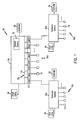
- FIG. 1 is a block diagram illustrating a packet switched network 10, such as an Ethernet (IEEE 802.3) network.
- the packet switched network includes integrated (i.e., single chip) multiport switches 12 that enable communication of data packets between network stations 14.
- Each network station 14, for example a client workstation, is typically configured for sending and receiving data packets at 10 Mbps or 100 Mbps according to IEEE 802.3 protocol.
- Each of the integrated multiport switches 12 are interconnected by gigabit Ethernet links 16, enabling transfer of data packets between subnetworks 18a, 18b, and 18c.
- each subnetwork includes a switch 12, and an associated group of network stations 14.
- Each switch 12 includes a switch port 20 that includes a media access control (MAC) module 22 and a packet classifier module 24.
- the MAC module 20 transmits and receives data packets to the associated network stations 14 across 10/100 Mbps physical layer (PHY) transceivers (not shown) according to IEEE 802.3u protocol.
- Each switch 12 also includes a switch fabric 25 configured for making frame forwarding decisions for received data packets.
- the switch fabric 25 is configured for layer 2 switching decisions based on source address, destination address, and VLAN information within the Ethernet (IEEE 802.3) header; the switch fabric 25 is also configured for selective layer 3 switching decisions based on evaluation of an IP data packet within the Ethernet packet.
- each switch 12 has an associated host CPU 26 and a buffer memory 28, for example an SSRAM.
- the host CPU 26 controls the overall operations of the corresponding switch 12, including programming of the switch fabric 25 and the packet classifier, described below.
- the buffer memory 28 is used by the corresponding switch 12 to store data frames while the switch fabric 25 is processing forwarding decisions for the received data packets.
- the switch fabric 25 is configured for performing layer 2 switching decisions and layer 3 switching decisions. Use of layer 3 switching decisions by the switch fabric 25 enables the switch fabric 25 to make intelligent decisions as far as how to handle a packet, including advanced forwarding decisions, and whether a packet should be considered a high-priority packet for latency-sensitive applications, such as video or voice.
- the packet classifier module 24 of Figure 1 is configured for multiple simultaneous comparisons between the incoming data stream and templates that identify the data format of the incoming data stream.
- users of the host processor 26 will specify policies that define how data packets having certain prescribed data values at selected portions of a received data packet should be handled by the switch fabric 25. These policies are implemented by loading into the switch fabric 25 a set of frame forwarding decisions, or aging function parameters, for each corresponding policy.
- the prescribed data values at selected portions of the received layer 2 data packet may be located within any portion of the layer 2 data packet.
- the packet classifier module 24 is able to detect the presence of data flows according to different network applications, for example hypertext transport protocol, SNMP, FTP, Telnet, etc..
- the switch fabric 25 could include one set of frame forwarding instructions and aging parameters for an HTTP packet, another set of frame forwarding instructions and aging parameters for an SNMP packet, and another set of frame forwarding instructions and aging parameters for a high-priority packet (e.g., video, or voice, etc.).
- a high-priority packet e.g., video, or voice, etc.
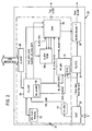
- FIG. 2 is a block diagram illustrating the packet classifier module 24 according to an embodiment of the present invention.
- the network switch port 20 includes a MAC 22, a receive FIFO buffer 27, a header modifier 29, and the packet classifier module 24.
- the packet classifier module 24, also referred to as a network switch port filter, is configured for identifying (i.e., evaluating) the incoming data packet at the network switch port 20, and supplying to the switch fabric 25 a tag that specifies the action to be performed on the data packet based on type of data packet being received.
- the packet classifier module 24 simultaneously compares the incoming data packet with a plurality of templates configured for identifying respective data formats.
- the packet classifier module 24, based on the comparison between the incoming data packet and the plurality of templates, identifies an equation to be executed that specifies the tag to be supplied to the switch fabric 25.
- the packet classifier module 24 generates a comparison result that identifies the incoming data packet by detecting at least one matched template from a plurality of templates. The packet classifier module 24 then identifies which of the equations includes the matched template, and generates the tag specified by the equation.
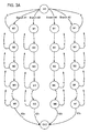
- Figures 3A and 3B are diagrams illustrating the simultaneous processing of two templates of an equation by the packet classifier module 24.
- Figure 3B illustrates how the equation Eq1 would actually be stored in the min term memory 70.
- the equation Eq1 includes four templates 62a, 62b, 62c, and 62d: the template 62a includes the min terms M1, M2, M3, M4, and M5; the template 62b includes the min terms M1, M2, M3, M4, and M6; the template 62c includes the min terms M1, M2, M3, M4, and M7; and the template 62d includes the min terms M1, M2, M3, M4, and M8.
- Each template 62 corresponds to a specific IP data format recognizable based on the header of the IP data packet 32.
- templates 62a and 62c may be configured for identifying an HTTP packet
- templates 62b and 62d be may be configured for identifying an SNMP packet.
- an HTTP packet is identified if it is in IPv4 format, the time to live field in IP is bigger than one, the protocol field in IP header is TCP, header checksum is correct, source TCP port is 80 or destination TCP port is 80.
- An SNMP packet is identified if it is in IPv4 format, the time to live field in IP is bigger than one, the protocol field in IP header is TCP, header checksum is correct, source TCP port is 25 or destination TCP port is 25.
- equation one specifies that a specific result (e.g., the tag having a specified value) should be output to the switch fabric 25 if either template 62a, 62b, 62c, or 62d are true.
- the min terms M1...M8 are arranged within the associated templates 62a and/or 62b in a prescribed order that corresponds to the relative position of a data byte in the incoming data stream.
- the min term M1 is configured for comparison with the first byte (B 1) of the IP packet
- the min term M2 is configured for comparison with a subsequent byte (B2) of the IP packet that follows B1
- the min term M3 is configured for comparison with a subsequent byte (B3) that follows B2, etc.
- the use of templates 62 having min terms in an order based on the relative position of a data byte in the incoming data stream enables multiple simultaneous comparisons between the incoming data stream and min terms.
- an incoming data packet can be compared to multiple templates to determine not only the data format of the incoming data packet, but also what action needs to be performed by the switch fabric 25.
- the packet classifier 24 also referred to as a network switch port filter, includes a min term memory 70 for storing the min term values (e.g., M1, M2, etc.), and a frame identifier 72 configured for identifying the type of layer 2 frame being received; in particular, identifying the type of layer 2 frame being received (e.g.., Ethernet, IEEE 802 to 3, etc.) enables identification of the start position 64 of the IP packet 32 within the layer 2 packet 30.
- the packet classifier 24 also includes a min term controller 74, a min term generator 76, an equation core 78, and an evaluation results memory 80.
- a processor interface module (pi_mod) 82 is used for transferring the generated min terms from the host CPU 26 into the min term memory 70.
- the min term controller 74 is configured for fetching the min terms from the min term memory 70 corresponding to a selected byte of the received IP frame.
- the min term controller 74 also includes a location converter configured for specifying the actual byte location (byte_location) of the start point in response to receiving a frame type (frm_type) signal from the frame identifier 72 that specifies the type of layer 2 frame.
- the min term controller 74 then forwards the min term values (M_STRU INFO) to the min term generator 76 and the equation core 78.
- the min term generator 76 performs the actual min term comparisons between the min terms fetched by the min term controller and the selected byte of the incoming data stream, and provides the min term comparison results (mt_result) to the equation core 78.
- the min term generator is configured for simultaneously comparing the incoming data stream to up to eight min terms.
- the equation core 78 is configured for generating a frame tag based on the min term comparison results received from the min term generator 76, relative to the relevant templates 62.
- the packet classifier module 24 enables each network switch port 20 to identify whether the received layer 2 data packet is carrying frame data for a prescribed network application, such as HTTP. SNMP, FTP, Telnet, etc..
- the packet classifier module 24 can be programmed with additional templates to specifically identify, from the received layer 2 data packet, the application state.
- network nodes communicate according to the prescribed network application, resulting in prescribed data flows between the two network nodes; hence, the layer 2 data packets transferred between the network nodes will include payload information that specifies the prescribed network application state, for example a request to initiate a session, acknowledgment, communication during the session, a request to terminate the session, and acknowledgment of termination of the session.
- the packet classifier.module 24 can be programmed with the appropriate templates to monitor the state of the data flow by evaluating the payload data of the layer 2 data packets; hence, the packet classifier module 24 can monitor the application state for the network application operating between the two network nodes, enabling the switching logic within the switch fabric 25 to perform application-based aging operations.
- FIG 4 is a diagram illustrating in detail the switch fabric 25 of Figure 1 according to an embodiment of the present invention.
- the switch fabric 25 includes switching logic 80 and a network switch address table 82.
- the network switch address table 82 may also be implemented external to the network switch 12 as an external address table.
- the switching logic 80 controls the learning (i.e., storing) of address table entries 84 within the network switch address table 82.
- Each address table entry 84 includes a MAC address field 84c, an IP address field 84d, and a switching information field 84e that provides corresponding layer 2 and/or layer 3 switching information for the network node having the corresponding MAC and/or IP addresses.
- Each address table entry 84 also includes an aging timer start field 84a configured for storing a start time for an aging timer, and an aging interval field 84b configured for storing the application-specific aging time interval, based on network application being supported by the determined data flow.
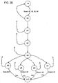
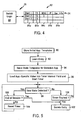
- Figure 5 is a flow diagram illustrating the method of performing application-based aging of the network switch address table 82 according to an embodiment of the present invention. Although illustrated as a flow diagram, actual implementation may be state-based, where a new state in the switching logic 80 is executed in response to prescribed action tags from the packet classifier module 24.
- the method begins in step 90, where the host CPU loads into the min term memory 70 of the packet classifier module 24 at least an initial set of application templates configured for identifying each of the network applications based on the received layer 2 data packet.
- a network node will initially transmit a request to begin a session according to one of the prescribed network applications; the packet classifier module 24, in response to detecting the initial request from the network node, sends a tag to the switch fabric 25 specifying a new network node and the corresponding identified network application.
- the switching logic 80 learns the entry in step 92 by adding another entry 84 to the network switch address table 82.
- the host CPU is also notified of the new data flow, and the host CPU may at that time store additional templates for the detected application into the min term memory 70 in step 94, enabling the packet classifier module 24 to identify each application state for the detected data flow. Alternately, all the templates may be loaded into the min term memory 70 at one time.
- the host CPU 26 In response to detecting the network application being supported by the corresponding received layer 2 data packet, the host CPU 26 loads the application-specific aging interval (e.g., T1) into the aging interval field 84b, and records the start time for the timer into the aging timer start field 84a in step 96.
- the application-specific aging interval e.g., T1
- the packet classifier module 24 of the network switch port 20 having received the layer 2 data packet continues to monitor for additional layer 2 data packets having payload data for the identified data flow of the network application. If in step 98 the packet classifier module 24 detects a new state for the existing data flow, and if in step 100 the new state indicates an end of a session for the data flow according to the identified network application, the packet classifier module 24 outputs an action tag specifying an end of the session to the switching logic 80, causing the switching logic 80 to delete the corresponding address table entry 84 in step 102.
- step 100 the new state is determined by the packet classifier module 24 to be an intermediate application state
- the packet classifier module 24 sends the appropriate tag to the switching logic 80, causing the switching logic 80 to reset the timer in step 104 by overriding the start time in field 84a with an updated value.
- the switching logic 80 continually monitors the application-specific aging interval by comparing its internal clock to the start time entry 84a relative to the aging interval entry 84b. If the stitching logic 80 determines that the application-specific timer has expired in step 106, indicating that the corresponding address table entry has not been accessed during the application-specific aging interval specified in the aging interval field 84b, the switching logic 80 deletes the entry in step 102.
- application-specific aging intervals are used, in combination with determined application state, to precisely determine when an address entry should be deleted from a network switch address table.
- an address table may be precisely maintained by the network switch based on the data flows encountered by the network switch.
Landscapes
- Engineering & Computer Science (AREA)
- Computer Networks & Wireless Communication (AREA)
- Signal Processing (AREA)
- Data Exchanges In Wide-Area Networks (AREA)
- Small-Scale Networks (AREA)
Applications Claiming Priority (3)
| Application Number | Priority Date | Filing Date | Title |
|---|---|---|---|
| US519848 | 2000-03-06 | ||
| US09/519,848 US7002955B1 (en) | 2000-03-06 | 2000-03-06 | Selective address table aging in a network switch based on application state determined from a received data packet |
| PCT/US2000/024026 WO2001067686A1 (en) | 2000-03-06 | 2000-09-01 | Selective address table aging in a network switch |
Publications (2)
| Publication Number | Publication Date |
|---|---|
| EP1262043A1 EP1262043A1 (en) | 2002-12-04 |
| EP1262043B1 true EP1262043B1 (en) | 2008-09-03 |
Family
ID=24070050
Family Applications (1)
| Application Number | Title | Priority Date | Filing Date |
|---|---|---|---|
| EP00959729A Expired - Lifetime EP1262043B1 (en) | 2000-03-06 | 2000-09-01 | Selective address table aging in a network switch |
Country Status (8)
| Country | Link |
|---|---|
| US (1) | US7002955B1 (ko) |
| EP (1) | EP1262043B1 (ko) |
| JP (1) | JP4767471B2 (ko) |
| KR (1) | KR100708428B1 (ko) |
| CN (1) | CN1178435C (ko) |
| DE (1) | DE60040170D1 (ko) |
| TW (1) | TWI232653B (ko) |
| WO (1) | WO2001067686A1 (ko) |
Cited By (1)
| Publication number | Priority date | Publication date | Assignee | Title |
|---|---|---|---|---|
| US11522774B2 (en) | 2021-04-12 | 2022-12-06 | Nxp B.V. | Network switch |
Families Citing this family (22)
| Publication number | Priority date | Publication date | Assignee | Title |
|---|---|---|---|---|
| DE10147419A1 (de) | 2001-09-26 | 2003-04-24 | Siemens Ag | Verfahren zur Erstellung einer dynamischen Adresstabelle für einen Koppelknoten in einem Datennetz und Verfahren zur Übertragung eines Datentelegramms |
| US7233991B2 (en) * | 2003-08-22 | 2007-06-19 | Clearmesh Networks, Inc. | Self-healing tree network |
| US20060149841A1 (en) * | 2004-12-20 | 2006-07-06 | Alcatel | Application session management for flow-based statistics |
| KR100656358B1 (ko) * | 2005-10-25 | 2006-12-11 | 한국전자통신연구원 | Mobile IP 환경에서의 핸드오버 수행 방법 |
| US7787462B2 (en) * | 2006-03-06 | 2010-08-31 | Cisco Technology, Inc. | Applying features to packets in the order specified by a selected feature order template |
| US8244855B1 (en) * | 2006-06-21 | 2012-08-14 | Qurio Holdings, Inc. | Application state aware mediating server |
| US8102863B1 (en) | 2006-06-27 | 2012-01-24 | Qurio Holdings, Inc. | High-speed WAN to wireless LAN gateway |
| CN101170517B (zh) * | 2007-12-06 | 2010-09-22 | 杭州华三通信技术有限公司 | 对控制会话表进行老化的方法 |
| US8625428B2 (en) | 2008-06-05 | 2014-01-07 | Telefonaktiebolaget Lm Ericsson (Publ) | Method and apparatus for handling a switch using a preferred destination list |
| US8392606B2 (en) * | 2008-09-23 | 2013-03-05 | Synapse Wireless, Inc. | Wireless networks and methods using multiple valid network identifiers |
| CN101488862B (zh) * | 2009-02-23 | 2012-02-08 | 中兴通讯股份有限公司 | 分布式以太网交换机及其内部的mac地址维护方法 |
| US8416701B1 (en) | 2009-04-30 | 2013-04-09 | Hewlett-Packard Development Company, L.P. | System and method for updating forwarding tables |
| CN102088642B (zh) * | 2009-12-02 | 2013-09-04 | 杭州华三通信技术有限公司 | 光纤通道架构合并方法、系统及交换机 |
| CN102315964B (zh) * | 2011-08-19 | 2013-12-18 | 华为技术有限公司 | 一种测试报文的环回方法及交换设备 |
| WO2013133400A1 (ja) | 2012-03-09 | 2013-09-12 | 日本電気株式会社 | 制御装置、通信システム、スイッチ制御方法及びプログラム |
| US9077562B2 (en) | 2012-06-08 | 2015-07-07 | Cisco Technology, Inc. | System and method for layer-2 multicast multipathing |
| US9178837B2 (en) * | 2012-07-17 | 2015-11-03 | Cisco Technology, Inc. | System and method for layer-2 network routing |
| CN104079424B (zh) | 2013-03-29 | 2017-07-11 | 国际商业机器公司 | 用于非对称链路聚合的装置和方法 |
| CN105704046A (zh) * | 2014-11-27 | 2016-06-22 | 中兴通讯股份有限公司 | 一种组播路由表项处理方法及装置 |
| WO2019005286A1 (en) | 2017-06-29 | 2019-01-03 | Obermeyer Henry K | IMPROVED REVERSIBLE PUMP-TURBINE INSTALLATION |
| CN113114570B (zh) * | 2020-01-13 | 2023-04-07 | 阿里巴巴集团控股有限公司 | 流表项的控制方法、装置及系统 |
| CN114024919A (zh) * | 2021-09-28 | 2022-02-08 | 苏州裕太微电子有限公司 | 一种实现以太网二层转发表精确老化的方法及系统 |
Family Cites Families (11)
| Publication number | Priority date | Publication date | Assignee | Title |
|---|---|---|---|---|
| US5128926A (en) * | 1990-03-21 | 1992-07-07 | Digital Equipment Corporation | Updating link state information in networks |
| JP2944531B2 (ja) * | 1996-09-12 | 1999-09-06 | 日本電気通信システム株式会社 | Lan間接続装置 |
| US5748628A (en) * | 1996-11-05 | 1998-05-05 | Interack Communications, Inc. | ISDN D-channel signaling discriminator |
| US5914956A (en) | 1997-02-03 | 1999-06-22 | Williams; Joel R. | Cache for improving the connection capacity of a communications switch |
| US5953335A (en) | 1997-02-14 | 1999-09-14 | Advanced Micro Devices, Inc. | Method and apparatus for selectively discarding packets for blocked output queues in the network switch |
| US6094435A (en) * | 1997-06-30 | 2000-07-25 | Sun Microsystems, Inc. | System and method for a quality of service in a multi-layer network element |
| US5909686A (en) | 1997-06-30 | 1999-06-01 | Sun Microsystems, Inc. | Hardware-assisted central processing unit access to a forwarding database |
| US6072809A (en) * | 1997-08-14 | 2000-06-06 | Lucent Technologies, Inc. | Statistical method for dynamically controlling the playback delay of network multimedia streams |
| JP4080599B2 (ja) * | 1998-06-17 | 2008-04-23 | 富士通株式会社 | 通信制御装置およびマルチキャスト対応lanに適用される通信制御方法 |
| AU6311299A (en) * | 1998-07-08 | 2000-02-01 | Broadcom Corporation | Network switching architecture with multiple table synchronization, and forwarding of both IP and IPX packets |
| US6571291B1 (en) * | 2000-05-01 | 2003-05-27 | Advanced Micro Devices, Inc. | Apparatus and method for validating and updating an IP checksum in a network switching system |
-
2000
- 2000-03-06 US US09/519,848 patent/US7002955B1/en not_active Expired - Lifetime
- 2000-09-01 EP EP00959729A patent/EP1262043B1/en not_active Expired - Lifetime
- 2000-09-01 CN CNB008192774A patent/CN1178435C/zh not_active Expired - Lifetime
- 2000-09-01 WO PCT/US2000/024026 patent/WO2001067686A1/en active Application Filing
- 2000-09-01 DE DE60040170T patent/DE60040170D1/de not_active Expired - Lifetime
- 2000-09-01 JP JP2001565591A patent/JP4767471B2/ja not_active Expired - Lifetime
- 2000-09-01 KR KR1020027011715A patent/KR100708428B1/ko active IP Right Grant
- 2000-09-06 TW TW089118236A patent/TWI232653B/zh not_active IP Right Cessation
Cited By (1)
| Publication number | Priority date | Publication date | Assignee | Title |
|---|---|---|---|---|
| US11522774B2 (en) | 2021-04-12 | 2022-12-06 | Nxp B.V. | Network switch |
Also Published As
| Publication number | Publication date |
|---|---|
| TWI232653B (en) | 2005-05-11 |
| EP1262043A1 (en) | 2002-12-04 |
| US7002955B1 (en) | 2006-02-21 |
| KR100708428B1 (ko) | 2007-04-18 |
| WO2001067686A1 (en) | 2001-09-13 |
| CN1451215A (zh) | 2003-10-22 |
| JP2003526279A (ja) | 2003-09-02 |
| DE60040170D1 (de) | 2008-10-16 |
| JP4767471B2 (ja) | 2011-09-07 |
| KR20020083173A (ko) | 2002-11-01 |
| CN1178435C (zh) | 2004-12-01 |
Similar Documents
| Publication | Publication Date | Title |
|---|---|---|
| EP1262043B1 (en) | Selective address table aging in a network switch | |
| US6571291B1 (en) | Apparatus and method for validating and updating an IP checksum in a network switching system | |
| US6925085B1 (en) | Packet classification using hash key signatures generated from interrupted hash function | |
| US6718379B1 (en) | System and method for network management of local area networks having non-blocking network switches configured for switching data packets between subnetworks based on management policies | |
| US6798788B1 (en) | Arrangement determining policies for layer 3 frame fragments in a network switch | |
| US6574240B1 (en) | Apparatus and method for implementing distributed layer 3 learning in a network switch | |
| US6934260B1 (en) | Arrangement for controlling learning of layer 3 network addresses in a network switch | |
| US6950434B1 (en) | Arrangement for searching packet policies using multi-key hash searches in a network switch | |
| US6700897B1 (en) | Apparatus and method for identifying data packet types in real time on a network switch port | |
| US6807183B1 (en) | Arrangement for reading a prescribed location of a FIFO buffer in a network switch port | |
| US6963565B1 (en) | Apparatus and method for identifying data packet at wire rate on a network switch port | |
| EP1303949B1 (en) | Apparatus and method for buffer-free evaluation of packet data bytes with multiple min terms | |
| US6728246B1 (en) | Arrangement for reducing layer 3 header data supplied to switching logic on a network switch | |
| US6711165B1 (en) | Apparatus and method for storing min terms in network switch port memory for access and compactness | |
| US6741594B1 (en) | Arrangement for identifying data packet types from multiple protocol formats on a network switch port | |
| US6678272B1 (en) | Apparatus and method using a register scheme for efficient evaluation of equations in a network switch | |
| US6728255B1 (en) | Apparatus and method for storing min terms in a network switch port memory for identifying data packet types in a real time | |
| US6714542B1 (en) | Apparatus and method for storing min terms in a central min term memory for efficient sharing by a plurality of network switch ports | |
| US6885666B1 (en) | Apparatus and method in a network switch for synchronizing transfer of a control tag to a switch fabric with transfer of frame data to a buffer memory | |
| WO2001080493A2 (en) | Method and device for layer 3 address learning | |
| US6693908B1 (en) | Apparatus and method for efficient evaluation of equations which generate frame tags in a network switch |
Legal Events
| Date | Code | Title | Description |
|---|---|---|---|
| PUAI | Public reference made under article 153(3) epc to a published international application that has entered the european phase |
Free format text: ORIGINAL CODE: 0009012 |
|
| 17P | Request for examination filed |
Effective date: 20020808 |
|
| AK | Designated contracting states |
Kind code of ref document: A1 Designated state(s): AT BE CH CY DE DK ES FI FR GB GR IE IT LI LU MC NL PT SE |
|
| RBV | Designated contracting states (corrected) |
Designated state(s): AT BE DE GB |
|
| GRAP | Despatch of communication of intention to grant a patent |
Free format text: ORIGINAL CODE: EPIDOSNIGR1 |
|
| RAP1 | Party data changed (applicant data changed or rights of an application transferred) |
Owner name: ADVANCED MICRO DEVICES, INC. |
|
| RBV | Designated contracting states (corrected) |
Designated state(s): DE GB |
|
| GRAS | Grant fee paid |
Free format text: ORIGINAL CODE: EPIDOSNIGR3 |
|
| GRAA | (expected) grant |
Free format text: ORIGINAL CODE: 0009210 |
|
| AK | Designated contracting states |
Kind code of ref document: B1 Designated state(s): DE GB |
|
| REG | Reference to a national code |
Ref country code: GB Ref legal event code: FG4D |
|
| REF | Corresponds to: |
Ref document number: 60040170 Country of ref document: DE Date of ref document: 20081016 Kind code of ref document: P |
|
| PLBE | No opposition filed within time limit |
Free format text: ORIGINAL CODE: 0009261 |
|
| STAA | Information on the status of an ep patent application or granted ep patent |
Free format text: STATUS: NO OPPOSITION FILED WITHIN TIME LIMIT |
|
| 26N | No opposition filed |
Effective date: 20090604 |
|
| PGFP | Annual fee paid to national office [announced via postgrant information from national office to epo] |
Ref country code: DE Payment date: 20190820 Year of fee payment: 20 |
|
| PGFP | Annual fee paid to national office [announced via postgrant information from national office to epo] |
Ref country code: GB Payment date: 20190830 Year of fee payment: 20 |
|
| REG | Reference to a national code |
Ref country code: DE Ref legal event code: R071 Ref document number: 60040170 Country of ref document: DE |
|
| REG | Reference to a national code |
Ref country code: GB Ref legal event code: PE20 Expiry date: 20200831 |
|
| PG25 | Lapsed in a contracting state [announced via postgrant information from national office to epo] |
Ref country code: GB Free format text: LAPSE BECAUSE OF EXPIRATION OF PROTECTION Effective date: 20200831 |