EP1261206A2 - Transmitting/receiving control method and device therefor - Google Patents
Transmitting/receiving control method and device therefor Download PDFInfo
- Publication number
- EP1261206A2 EP1261206A2 EP02253463A EP02253463A EP1261206A2 EP 1261206 A2 EP1261206 A2 EP 1261206A2 EP 02253463 A EP02253463 A EP 02253463A EP 02253463 A EP02253463 A EP 02253463A EP 1261206 A2 EP1261206 A2 EP 1261206A2
- Authority
- EP
- European Patent Office
- Prior art keywords
- flow control
- video
- content
- transmitting apparatus
- audio data
- Prior art date
- Legal status (The legal status is an assumption and is not a legal conclusion. Google has not performed a legal analysis and makes no representation as to the accuracy of the status listed.)
- Withdrawn
Links
Images


Classifications
-
- G—PHYSICS
- G11—INFORMATION STORAGE
- G11B—INFORMATION STORAGE BASED ON RELATIVE MOVEMENT BETWEEN RECORD CARRIER AND TRANSDUCER
- G11B20/00—Signal processing not specific to the method of recording or reproducing; Circuits therefor
- G11B20/10—Digital recording or reproducing
-
- H—ELECTRICITY
- H04—ELECTRIC COMMUNICATION TECHNIQUE
- H04N—PICTORIAL COMMUNICATION, e.g. TELEVISION
- H04N21/00—Selective content distribution, e.g. interactive television or video on demand [VOD]
- H04N21/40—Client devices specifically adapted for the reception of or interaction with content, e.g. set-top-box [STB]; Operations thereof
- H04N21/43—Processing of content or additional data, e.g. demultiplexing additional data from a digital video stream; Elementary client operations, e.g. monitoring of home network or synchronising decoder's clock; Client middleware
- H04N21/4302—Content synchronisation processes, e.g. decoder synchronisation
- H04N21/4305—Synchronising client clock from received content stream, e.g. locking decoder clock with encoder clock, extraction of the PCR packets
-
- H—ELECTRICITY
- H04—ELECTRIC COMMUNICATION TECHNIQUE
- H04N—PICTORIAL COMMUNICATION, e.g. TELEVISION
- H04N21/00—Selective content distribution, e.g. interactive television or video on demand [VOD]
- H04N21/40—Client devices specifically adapted for the reception of or interaction with content, e.g. set-top-box [STB]; Operations thereof
- H04N21/43—Processing of content or additional data, e.g. demultiplexing additional data from a digital video stream; Elementary client operations, e.g. monitoring of home network or synchronising decoder's clock; Client middleware
- H04N21/4302—Content synchronisation processes, e.g. decoder synchronisation
- H04N21/4307—Synchronising the rendering of multiple content streams or additional data on devices, e.g. synchronisation of audio on a mobile phone with the video output on the TV screen
- H04N21/43072—Synchronising the rendering of multiple content streams or additional data on devices, e.g. synchronisation of audio on a mobile phone with the video output on the TV screen of multiple content streams on the same device
-
- H—ELECTRICITY
- H04—ELECTRIC COMMUNICATION TECHNIQUE
- H04N—PICTORIAL COMMUNICATION, e.g. TELEVISION
- H04N21/00—Selective content distribution, e.g. interactive television or video on demand [VOD]
- H04N21/40—Client devices specifically adapted for the reception of or interaction with content, e.g. set-top-box [STB]; Operations thereof
- H04N21/43—Processing of content or additional data, e.g. demultiplexing additional data from a digital video stream; Elementary client operations, e.g. monitoring of home network or synchronising decoder's clock; Client middleware
- H04N21/436—Interfacing a local distribution network, e.g. communicating with another STB or one or more peripheral devices inside the home
- H04N21/4363—Adapting the video stream to a specific local network, e.g. a Bluetooth® network
- H04N21/43632—Adapting the video stream to a specific local network, e.g. a Bluetooth® network involving a wired protocol, e.g. IEEE 1394
-
- H—ELECTRICITY
- H04—ELECTRIC COMMUNICATION TECHNIQUE
- H04N—PICTORIAL COMMUNICATION, e.g. TELEVISION
- H04N5/00—Details of television systems
- H04N5/76—Television signal recording
- H04N5/765—Interface circuits between an apparatus for recording and another apparatus
- H04N5/775—Interface circuits between an apparatus for recording and another apparatus between a recording apparatus and a television receiver
Definitions
- the present invention relates to a transmitting apparatus for transmitting the audio data reproduced from the recording medium to the network and its control method, and a receiving apparatus for receiving the above audio data and its control method.
- the digital audio/video system capable of achieving the high quality-of-audio reproduction by transmitting the digital audio data or digital video data, which is reproduced by the reproducing device such as the DVD (Digital Versatile Disc) player, etc., to the network including the transmission line such as the serial bus (IEEE Std.1394-1955 IEEE Standard for a High Performance Serial Bus) based on the IEEE 1394 standard, etc. and also receiving the audio data by the receiving apparatus such as the amplifier, etc., is being implemented.
- the serial bus IEEE Std.1394-1955 IEEE Standard for a High Performance Serial Bus
- such a flow control is carried out that the audio data are stored in the buffer on the receiving apparatus side and also the reproducing speed on the transmitter side is controlled within the speed variation of ⁇ 1 % not to cause the overflow or the underflow of such buffer.
- the receiving apparatus can read the audio data stored in the buffer by using the clock with the quartz precision, the high quality audio output can be achieved without the jitter component.
- the present invention has been made in view of the problems mentioned above, and it is an object of the present invention to provide a transmitting apparatus and a control method therefor and a receiving apparatus and a control method therefor capable of eliminating the distortion of the video and also attaining the lip synchronization even when the portion of the DVD-Audio disc, etc., in which the video and the audio are contained, is reproduced.
- a transmitting apparatus enabling to reproduce a recording medium in compliance with a flow control and to transmit video data and audio data to a network, the transmitting apparatus having:
- the transmitting apparatus according to the first aspec, further having:
- the display video is changed into the warning display.
- the user who looks at this warning display can cancel the flow control.
- the transmitting apparatus according to the first aspect of the invention, further comprising:
- the reproduction is temporarily stopped and then the flow control can be canceled at a time when the flow control cancel signal is transmitted from the receiver side.
- a receiving apparatus for selecting flow control that stores audio data transmitted from a transmitting apparatus in a buffer and reads the stored audio data based on a reference clock and normal reception that receives a transmitted audio data based on a PLL clock, the receiving apparatus having:
- the audio data of the content with the video is received, the normal reception to receive the data based on the PLL clock can be executed by canceling the flow control, and also the flow control can be canceled by transmitting the flow control cancel command to the transmitting apparatus.
- the audio reproduction to eliminate the distortion of the video and to attain the lip synchronization can be achieved.
- the receiving apparatus further having detecting device for detecting that the audio data stored in the buffer becomes empty.
- the changing device changes the flow control to the normal reception in response to detection that the audio data becomes empty.
- the receiving apparatus further having detecting device for acquiring contents information from the transmitting apparatus to detect whether content reproduced by the transmitting apparatus is content with video.
- the changing device changes the flow control to the normal reception in response to detection that the content reproduced by the transmitting apparatus is the content with video.
- the normal reception not to use the buffer can be carried out by canceling automatically the flow control.
- a controlling method of a transmitting apparatus enabling to reproduce a recording medium in compliance with a flow control and to transmit video data and audio data to a network, having the steps of:
- controlling method according to the seventh aspect of the invention further having the steps of:
- the display video is changed to the warning display.
- the user who looks at this warning display can cancel the flow control.
- controlling method according to the seventh aspect of the invention further having the steps of:
- the reproduction is temporarily stopped and then the flow control can be canceled at a time when the flow control cancel signal is transmitted from the receiver side.
- a controlling method of a receiving apparatus for selecting flow control that stores audio data transmitted from a transmitting apparatus in a buffer and reads stored audio data based on a reference clock and normal reception that receives a transmitted audio data based on a PLL clock, the controlling method having the steps of:
- the audio reproduction to eliminate the blink of the video and attain the lip synchronization can be achieved.
- the controlling method according to the tenth aspect of the invention, further having the steps of detecting that the audio data stored in the buffer becomes empty.
- the step of changing the flow control to the normal reception changes the flow control to the normal reception in response to detection that the audio data becomes empty.
- the controlling method according to the tenth aspect of the invention, further having the steps of acquiring contents information from the transmitting apparatus to detect whether content reproduced by the transmitting apparatus is content with video.
- the step of changing the flow control to the normal reception changes the flow control to the normal reception in response to detection that the content reproduced by the transmitting apparatus are the content with video.
- the normal reception not to use the buffer can be carried out by canceling automatically the flow control.
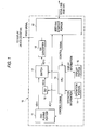
- FIG.1 is a block diagram showing a configuration of the transmitting apparatus (DVD player) according to first to fourth embodiments.
- the transmitting apparatus (DVD player) 10 has a DVD playing portion 11, an I/F portion 12 based on the IEEE 1394 standard, a CPU 13, an operation portion 14, a display portion 15, a GUI 16, a video data switch 17, and a DA converter 18.
- the DVD playing portion 11 is connected to the video data switch 17 to output the video data VD 11 of the reproduced contents, connected to the I/F portion 12 to output the audio data AD11 of the reproduced contents, and connected to the CPU 13 to input/output the control signal into/from the CPU 13.
- the I/F portion 12 is connected to the serial bus based on the IEEE 1394 standard and connected to the network. Also, the I/F portion 12 is connected to input/output the control signal into/from the CPU 13 and also connected to receive the audio data AD11.
- the CPU 13 is connected to receive the operation information, which is used to operate the transmitting apparatus (DVD player) 10 from the outside, from the operation portion 14 and to output the display information to the display portion 15 that displays the internal information to the outside, respectively.
- the CPU 13 is constructed to control respective blocks in the transmitting apparatus (DVD player) 10 and to input/output the control signal into/from the DVD playing portion 11, the I/F portion 12, the GUI 16, and the video data switch 17.
- the GUI 16 is connected to receive the control signal from the CPU 13 and to output the video data VD12 for the warning display to the video data switch 17.
- the video data switch 17 is connected to receive the video data VD11 and the video data VD12 for the warning display and to output the video data VD13 to the DA converter 18.
- the DA converter 18 is connected to receive the video data VD13 and to output the DA-converted analog video signal to the outside.
- FIG.2 is a block diagram showing a configuration of a receiving apparatus (amplifier) according to the first to fourth embodiments.
- the receiving apparatus (amplifier) 20 has an I/F portion 21, a buffer 22, a data changing switch 23, an audio processing portion 24, a DA converter 25, reference clock generators 26a, 26b, a reference clock changing switch 27, a CPU 28, an operation portion 29, and a display portion 30.
- the I/F portion 21 is connected to a serial bus based on the IEEE 1394 standard and connected to the network. Also, the I/F portion 21 is connected to input/output the control signal into/from the CPU 28, and also is connected to output the audio data AD21 to the buffer 22.
- the buffer 22 is connected to output the audio data AD22 to the data changing switch 23, and also is connected to output the buffer information to the CPU 28 and to receive the control signal from the CPU 28.
- the data changing switch 23 is connected to switch the input audio data AD21 and the audio data AD22 and to output the audio data AD23 to the audio processing portion 24. Also, the data changing switch 23 is connected to receive the control signal from the CPU 28.
- the audio processing portion 24 is connected to output the audio data AD24 to the DA converter 25, and also is connected to receive the control signal from the CPU 28.
- the DA converter 25 is constructed such that such converter can connect the DA-converted audio signal to an external device (e.g., loudspeaker), etc.
- an external device e.g., loudspeaker
- the first reference clock generators 26a is constructed to generate the first reference clock CKa (used in the case of the flow control).
- the second reference clock generators 26b is constructed to generate the second reference clock CKb (used in the case of the normal reception) by PLL.
- the reference clock changing switch 27 is constructed to receive the first reference clock CKa supplied from the first reference clock generator 26a, the second reference clock CKb supplied from the second reference clock generator 26b, and the reference clock changing control signal being output from the CPU 28 and to supply the changed reference clock CK to respective blocks (the I/F portion 21, the buffer 22, and the DA converter 25) in the receiving apparatus (amplifier) 20.
- the CPU 28 is connected to receive the operation information, which is used to operate the receiving apparatus (amplifier) 20 from the outside, from the operation portion 29 and to output the display information to the display portion 30 that displays the internal information to the outside, respectively.
- the CPU 28 is constructed to control respective blocks in the receiving apparatus (amplifier) 20. More particularly, the CPU 28 is constructed to input/output the control signal into/from the I/F portion 21, to receive the buffer information from the buffer 22, to output the control signal to the buffer 22, to output the control signal to the reference clock changing switch 27, to output the control signal to the data changing switch 23, and to output the control signal to the audio processing portion 24.
- the transmitting apparatus (DVD player) 10 reproduces the data from the recording medium such as the DVD-Audio disc, etc. in compliance with flow control and then transmits the video data and the audio data to the network.
- the feature of the transmitting apparatus (DVD player) 10 is that a plurality of functions for executing the flow control by transmitting the control signal from the CPU 13 are provided. These functions are given as follows.
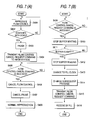
- steps S101 to S105 correspond to the control method of the transmitting apparatus .
- the transmitting apparatus (DVD player) 10 executes the reproduction in accordance with the flow control (step S101).
- step S102 the process of detecting whether or not the data reproduced by the DVD playing portion 11 are the contents with the video is carried out. Then, the process in step S103 is carried out if the contents with the video is detected as the data (Yes) whereas the process goes back to step S101 unless the contents with the video is detected as the data (No).
- the CPU 13 sends the control command to the GUI 16, then the GUI 16 transmits the video data VD12 that causes to display the warning to the user to the video data switch 17, and then the video data switch 17 receives the video data changing control signal transmitted from the CPU 13 to output the video data for the warning display to the DA converter 18 (VD13).
- the analog video signal that is obtained by DA-converting this VD13 by virtue of the DA converter 18 is output to the external monitor to display the video of the warning display (e.g., the video of the warning display indicating "The video cannot be displayed because the flow control is being reproduced. Please cancel the flow control to display the video") on the monitor (step S103).
- the video of the warning display e.g., the video of the warning display indicating "The video cannot be displayed because the flow control is being reproduced. Please cancel the flow control to display the video
- step S104 the user pushes the ON/OFF button, or the like provided on the operation portion 29 of the receiving apparatus 20 to detect whether or not the CPU 13 has received the flow control cancel command transmitted from the receiving apparatus 20 (step S104). Then, the flow control is canceled in step S105 if the flow control cancel command has been received (Yes), while the process returns to step S103 unless the flow control cancel command has been received (No).
- the video data switch 17 receives the video data changing control signal transmitted from the CPU 13 and then outputs the video data VD11 of the contents to the DA converter 18 (VD13). Accordingly, the contents video is displayed on the external monitor (step S106).
- a configuration of the transmitting apparatus (DVD player) 10 according to the second embodiment is similar to that of the first embodiment, and the same is true of a configuration of the receiving apparatus (amplifier) 20.
- the present embodiment corresponds to the reproducing track change of the transmitting apparatus (DVD player) 10, and also corresponds to the case where the track is changed from the track containing the audio contents only to the track containing the video and the audio contents.
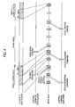
- timings of control signals and A&M data between the transmitting apparatus and the receiving apparatus will be shown in FIG.4 and explained hereunder.
- the track is changed from the track n containing the audio contents only to the track n+1 containing the video and audio contents via the pause mode.
- the receiving apparatus 20 sends out a status acquiring request command to the transmitting apparatus 10 at a constant interval, and then this status acquiring request command is stored in the asynchronous transmission area.
- the transmitting apparatus 10 that received the status acquiring request command sends out the signal indicating the pause (caused by switching to the video reproduction) state, and this signal is stored in the asynchronous transmission area. If the receiving apparatus, which received this signal, decided that such pause is caused by switching to the video reproduction, the flow control cancel command is sent out from the receiving apparatus 20 after the processes in the receiver side are ended. Then, the flow control cancel command is stored in the asynchronous transmission area.
- the transmitting apparatus (DVD player) 10 is constructed to transmit the reproduced data to the network and make it possible to execute the flow control.
- the receiving apparatus (amplifier) 20 is constructed to select the flow control that stores the data received from the network in the buffer and reads the data in the buffer based on the first reference clock or the normal reception that receives the data received from the network based on the second reference clock.
- the feature of the transmitting apparatus (DVD player) 10 is that a plurality of functions for executing the flow control by transmitting the control signal from the CPU 13 are provided. These functions are given as follows.
- the feature of the receiving apparatus (amplifier) 20 is that a plurality of functions for executing the flow control by transmitting the control signal from the CPU 28 are provided. These functions are given as follows.
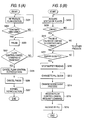
- steps S201 to S207 in (A) show a flow control method on the transmitting apparatus side
- steps S208 to S216 in (B) show a flow control method on the receiving apparatus side.
- the transmitting apparatus (DVD player) 10 is carrying out the flow control reproduction (step S201).
- step S202 the process of detecting whether or not the data reproduced by the DVD playing portion 11 are the contents with the video is carried out. Then, the process in step S203 is carried out if the contents with the video are detected as the data (Yes), while the process goes back to step S201 unless the contents with the video are detected as the data (No).
- step S203 the DVD playing portion 11 is set in the pause mode.
- step S204 the process of detecting whether or not the flow control cancel command is received is carried out. Then, the flow control is canceled in step S205 if the flow control cancel command is received (Yes) whereas the pause mode in step S203 is maintained unless the flow control cancel command is received (No).
- step S206 the pause mode of the DVD playing portion 11 is canceled.
- a controlling method on the receiving apparatus (amplifier) 20 side will be explained hereunder.
- the receiving apparatus (amplifier) 20 is carrying out the flow control reception.
- the status of the transmitting apparatus (DVD player) 10 is acquired (step S208).
- step S209 the process of detecting whether or not the pause status command is received from the transmitting apparatus (DVD player) 10 is carried out. Then, the process in step S210 is carried out if the pause status command is received (Yes) whereas the process returns to step S208 unless the pause status command is received (No).
- step S210 the process of detecting whether or not the received pause status command indicates that the pause is caused by the change into the contents with the video is carried out. Then, the process in step S211 is carried out if it is detected that the pause is caused by the change into the contents with the video (Yes), while the process is shifted to other process (not shown) unless it is detected that the pause is caused by the change into the contents with the video (No).
- step S211 it is detected whether or not the buffer 22 is empty. Then, the process in step S212 is carried out if it is detected whether or not the buffer 22 is empty (Yes) whereas the process of detecting whether or not the buffer is empty is repeated unless it is detected whether or not the buffer 22 is empty (No).
- the reading of the audio data AD22 from the buffer 22 is stopped by sending the reading stop control signal from the CPU 28 to the buffer 22 (step S212).
- the reference clock CK is changed from the first reference clock CKa to the second reference clock CKb (clock by the PLL) by sending the reference clock changing command from the CPU 28 to the reference clock changing switch 27 (step S213).
- the audio data AD23 to the audio processing portion 24 is changed from the audio data AD22 to the audio data AD21 by sending the change control signal from the CPU 28 to the switch 23 (step S214).
- step S216 the normal reception using the second reference clock CKb by the PLL is carried out.
- a configuration of the receiving apparatus (amplifier) 20 according to the third embodiment is similar to that of the first embodiment, and the same is true of a configuration of the transmitting apparatus (DVD player) 10.
- the receiving apparatus (amplifier) 20 is constructed to select the flow control that stores the data received from the network in the buffer and reads the data in the buffer based on the first reference clock or the normal reception that receives the data received from the network based on the second reference clock.
- the audio data are transmitted from the transmitting apparatus (DVD player) 20, for example.
- the feature of the receiving apparatus (amplifier) 20 is that a plurality of functions for executing the flow control by transmitting the control signal from the CPU 28 are provided. These functions are given as follows.
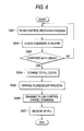
- the receiving apparatus (amplifier) 20 is carrying out the flow control receiving process using the first reference clock CKa (step S301).
- the contents information of the transmitting apparatus (DVD player) 10 is acquired by the contents information acquiring command (step S302).
- step S303 the process of detecting whether or not the contents are the contents with the video is carried out according to the obtained contents information of the transmitting apparatus (DVD player) 10 (step S303). Then, the process in step S304 is carried out if it is detected that the contents are the contents with the video (Yes), while the process goes back to step S301 unless it is detected that the contents are the contents with the video (No).
- the reference clock CK is changed from the first reference clock CKa to the PLL clock CKb by sending the reference clock change control signal from the CPU 28 to the reference clock changing switch 27 (step S304).
- the audio data AD23 to the audio processing portion 24 is changed from the audio data AD22 to the audio data AD21 by sending the change control signal from the CPU 28 to the switch 23 (step S305).
- step S306 the flow control cancel command is transmitted to the transmitting apparatus 10 (step S306).
- step S307 the normal reception using the PLL clock CKb is executed (step S307).
- a configuration of the transmitting apparatus (DVD player) 10 according to the fourth embodiment is similar to that of the first embodiment, and the same is true of a configuration of the receiving apparatus (amplifier) 20.
- the transmitting apparatus (DVD player) 10 is constructed to transmit the reproduced data to the network and make it possible to execute the flow control
- the receiving apparatus (amplifier) 20 is constructed to select the flow control reception that stores the data received from the network in the buffer and reads the data in the buffer based on the first reference clock or the normal reception that receives the data received from the network based on the second reference clock.
- the feature of the transmitting apparatus (DVD player) 10 is that a plurality of functions for executing the flow control by transmitting the control signal from the CPU 13 are provided. These functions are given as follows.
- the feature of the receiving apparatus (amplifier) 20 is that a plurality of functions for executing the flow control by transmitting the control signal from the CPU 28 are provided. These functions are given as follows.
- steps S401 to S408 in (A) show a controlling method on the transmitting apparatus side
- steps S409 to S416 in (B) show a controlling method on the receiving apparatus side.
- the transmitting apparatus (DVD player) 10 is carrying out the flow control reproduction (step S401).
- step S402 the process of detecting whether or not the data reproduced by the DVD playing portion 11 are the contents with the video is carried out (step S402). Then, the process in step S403 is carried out if the contents with the video are detected as the data (Yes), while the process goes back to step S401 unless the contents with the video are detected as the data (No).
- step S403 the DVD playing portion 11 is set in the pause mode.
- the flow control cancel request command is transmitted to the receiving apparatus (amplifier) 20 side (step S404).
- step S405 the process of detecting whether or not the flow control cancel command is received is carried out. Then, the process in step S406 is executed if the flow control cancel command is received (Yes) whereas the pause mode is maintained unless the flow control cancel command is received (No).
- step S406 the flow control is canceled.
- step S407 the pause mode of the DVD playing portion 11 is canceled.
- a controlling method on the receiving apparatus (amplifier) 20 side will be explained hereunder.
- the receiving apparatus (amplifier) 20 is carrying out the flow control reception using the first reference clock CKa.
- step S409 It is detected whether or not the flow control cancel request command is received (step S409). Then, the process in step S410 is carried out if the flow control cancel request command is received (Yes), while the present status is maintained unless the flow control cancel request command is received (No).
- step S412 it is detected whether or not the buffer 22 is empty (step S411). Then, the process in step S412 is carried out if it is detected that the buffer 22 is empty (Yes), while the process of detecting whether or not the buffer 22 is empty is repeated unless it is detected that the buffer 22 is empty (No) .
- the reading of the audio data AD 22 from the buffer 22 is stopped by sending the reading stop control signal from the CPU 28 to the buffer 22 (step S412).
- the reference clock CK is changed from the first reference clock CKa to the second reference clock CKb (clock by the PLL) by sending the reference clock changing command from the CPU 28 to the reference clock changing switch 27 (step S413).
- the audio data AD23 to the audio processing portion 24 is changed from the audio data AD22 to the audio data AD21 by sending the change control signal from the CPU 28 to the switch 23 (step S414).
- step S416 the normal reception using the second reference clock CKb by the PLL is carried out.
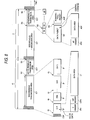
- FIG.8 is a view explaining a data structure in the isochronous cycle.
- the isochronous cycle IC is constructed with a cycle start packet CSP that is always inserted before the head of the isochronous cycle IC to set standard times of all nodes, an isochronous transmission area ICT that has isochronous packets IP of a plurality of channels in each of which the data corresponding to each channel are contained, and an asynchronous transmission area ACT in which asynchronous data such as the control signal, etc. are contained.
- a sub-action gap SG that is a time interval to indicate the end of the isochronous transmission area ICT or the end of an sub-action SA is inserted after the end of each isochronous transmission area ICT and the end of the asynchronous transmission area ACT.
- an isochronous gap IG that is a time interval to indicate the end of each packet is inserted between the isochronous packets IP and between the cycle start packet CSP and the top isochronous packet IP.
- a length of the above sub-action gap SG is set longer than a length of the isochronous gap IG.
- the isochronous packet IP has an IP (Isochronous Packet) header IPH that contains the information indicating an amount of data in each isochronous packet IP, the information indicating the channel for transmitting the information in each isochronous packet IP, etc., a CIP (Common Isochronous Packet) header CIPH, and a data area DF that contains A&M data.
- IP Isochronous Packet
- CIP Common Isochronous Packet
- the asynchronous transmission area ACT has a plurality of asynchronous sub-actions SA.
- Each asynchronous sub-action SA has a data packet DP in which the data such as the control information being asynchronously transmitted are contained, and an acknowledge packet ACP in which the data used for the reply from the destination node are contained.
- an acknowledge gap AG that is a time interval to indicate the end of the data packet DP is inserted between the data packet DP and the acknowledge packet ACP.
- the data packet DP is constructed with an AP (Asynchronous Packet) header APH that contains the information indicating the address of each data packet DP, etc., and a data area ADF that contains the control signal, etc.
- AP Asynchronous Packet
- the transmitting apparatus and the receiving apparatus capable of eliminating the distortion of the video and also attaining the lip synchronization even when the portion in which the video and the audio are contained is reproduced.
Landscapes
- Engineering & Computer Science (AREA)
- Signal Processing (AREA)
- Multimedia (AREA)
- Computer Networks & Wireless Communication (AREA)
- Signal Processing For Digital Recording And Reproducing (AREA)
- Television Signal Processing For Recording (AREA)
- Small-Scale Networks (AREA)
- Two-Way Televisions, Distribution Of Moving Picture Or The Like (AREA)
Abstract
Description
Claims (12)
- A transmitting apparatus enabling to reproduce a recording medium in compliance with a flow control and to transmit video data and audio data to a network, the transmitting apparatus comprising:a first detecting device for detecting whether a reproduced content is a content with video;a second detecting device for detecting reception of a flow control cancel command output from a receiving apparatus that receives the audio data, if the reproduced content is the content with the video; anda flow control canceling device for canceling the flow control in response to detection of the flow control cancel command.
- The transmitting apparatus according to claim 1, further comprising:a generating device for generating a warning display signal;a device for outputting the warning display signal as a video output signal if the reproduced content is the content with video; anda device for outputting a video signal for the content with the video as the video output signal after the flow control is canceled.
- The transmitting apparatus according to claim 1, further comprising:a device for stopping temporarily reproduction of the recording medium if the reproduced content is the content with video; anda device for canceling the temporary stop after the flow control is canceled.
- A receiving apparatus for selecting flow control that stores audio data transmitted from a transmitting apparatus in a buffer and reads the stored audio data based on a reference clock and normal reception that receives a transmitted audio data based on a PLL clock, the receiving apparatus comprising:a changing device for changing the flow control to the normal reception; anda device for transmitting a flow control cancel command to the transmitting apparatus after changing to the normal reception is executed.
- The receiving apparatus according to claim 4, further comprising detecting device for detecting that the audio data stored in the buffer becomes empty,
wherein the changing device changes the flow control to the normal reception in response to detection that the audio data becomes empty. - The receiving apparatus according to claim 4, further comprising detecting device for acquiring contents information from the transmitting apparatus to detect whether content reproduced by the transmitting apparatus is content with video,
wherein the changing device changes the flow control to the normal reception in response to detection that the content reproduced by the transmitting apparatus is the content with video. - A controlling method of a transmitting apparatus enabling to reproduce a recording medium in compliance with a flow control and to transmit video data and audio data to a network, comprising the steps of:detecting whether a reproduced content is a content with video;detecting reception of a flow control cancel command output from a receiving apparatus, if the reproduced content is the content with the video; andcanceling the flow control in response to detection of the flow control cancel command.
- The controlling method according to claim 7, further comprising the steps of:generating a warning display signal;outputting the warning display signal as a video output signal if the reproduced content is the content with video; andoutputting a video signal for the content with the video as the video output signal after the flow control is canceled.
- The controlling method according to claim 7, further comprising the steps of:stopping temporarily reproduction of the recording medium if the reproduced content is the content with video; andcanceling the temporary stop after the flow control is canceled.
- A controlling method of a receiving apparatus for selecting flow control that stores audio data transmitted from a transmitting apparatus in a buffer and reads stored audio data based on a reference clock and normal reception that receives a transmitted audio data based on a PLL clock, the controlling method comprising the steps of:changing the flow control to the normal reception; andtransmitting a flow control cancel command to the transmitting apparatus after changing into the normal reception is executed.
- The controlling method according to claim 10, further comprising the steps of detecting that the audio data stored in the buffer becomes empty,
wherein the step of changing the flow control to the normal reception changes the flow control to the normal reception in response to detection that the audio data becomes empty. - The controlling method according to claim 10, further comprising the steps of acquiring contents information from the transmitting apparatus to detect whether content reproduced by the transmitting apparatus is content with video,
wherein the step of changing the flow control to the normal reception changes the flow control to the normal reception in response to detection that the content reproduced by the transmitting apparatus are the content with video.
Applications Claiming Priority (2)
| Application Number | Priority Date | Filing Date | Title |
|---|---|---|---|
| JP2001148532 | 2001-05-17 | ||
| JP2001148532A JP4166964B2 (en) | 2001-05-17 | 2001-05-17 | Transmitting apparatus and control method thereof, receiving apparatus and control method thereof |
Publications (2)
| Publication Number | Publication Date |
|---|---|
| EP1261206A2 true EP1261206A2 (en) | 2002-11-27 |
| EP1261206A3 EP1261206A3 (en) | 2003-11-26 |
Family
ID=18993829
Family Applications (1)
| Application Number | Title | Priority Date | Filing Date |
|---|---|---|---|
| EP02253463A Withdrawn EP1261206A3 (en) | 2001-05-17 | 2002-05-15 | Transmitting/receiving control method and device therefor |
Country Status (6)
| Country | Link |
|---|---|
| US (2) | US7295761B2 (en) |
| EP (1) | EP1261206A3 (en) |
| JP (1) | JP4166964B2 (en) |
| KR (1) | KR100562817B1 (en) |
| CN (1) | CN1226736C (en) |
| TW (1) | TW591614B (en) |
Families Citing this family (4)
| Publication number | Priority date | Publication date | Assignee | Title |
|---|---|---|---|---|
| JP4625350B2 (en) * | 2005-03-15 | 2011-02-02 | 株式会社ディーアンドエムホールディングス | Data transmission device, data reception device, and data transmission / reception system |
| JPWO2007000836A1 (en) * | 2005-06-29 | 2009-01-22 | 株式会社ディーアンドエムホールディングス | Playback device |
| KR101010510B1 (en) * | 2008-09-18 | 2011-01-28 | 양승석 | Push button toothpaste |
| AU2010257332A1 (en) * | 2009-09-11 | 2011-03-31 | Roil Results Pty Limited | A method and system for determining effectiveness of marketing |
Family Cites Families (15)
| Publication number | Priority date | Publication date | Assignee | Title |
|---|---|---|---|---|
| DE3855742T2 (en) * | 1987-05-15 | 1997-07-03 | Canon Kk | Playback device |
| US5815634A (en) * | 1994-09-30 | 1998-09-29 | Cirrus Logic, Inc. | Stream synchronization method and apparatus for MPEG playback system |
| KR0136025B1 (en) * | 1994-12-30 | 1998-05-15 | 배순훈 | Video compact disc with caption data recorded thereon and system for handling the same |
| US5899578A (en) * | 1995-12-25 | 1999-05-04 | Sony Corporation | Digital signal processor, processing method, digital signal recording/playback device and digital signal playback method |
| JP2970558B2 (en) * | 1996-10-25 | 1999-11-02 | 日本電気株式会社 | Audio / video / computer graphics synchronous reproduction / synthesis method and method |
| US6208802B1 (en) * | 1997-08-07 | 2001-03-27 | Matsushita Electric Industrial Co., Ltd. | Optical disk, reproduction apparatus, and reproduction method |
| JP3952568B2 (en) | 1998-01-12 | 2007-08-01 | ソニー株式会社 | Digital audio signal transmission apparatus and digital audio signal transmission method |
| US6289066B1 (en) * | 1998-06-11 | 2001-09-11 | Hewlett-Packard Company | Method and apparatus for recentering an elasticity FIFO when receiving 1000BASE-X traffic using minimal information |
| JP2000015179A (en) | 1998-06-30 | 2000-01-18 | Honda Electronic Co Ltd | Ultrasonic vibration element |
| JP2000151719A (en) | 1998-11-05 | 2000-05-30 | Sony Corp | Data processing circuit and data transmission system |
| JP3994555B2 (en) | 1998-11-18 | 2007-10-24 | ソニー株式会社 | Data processing circuit and data transmission system |
| JP2000215598A (en) | 1999-01-27 | 2000-08-04 | Sony Corp | Digital signal transmission method, digital signal transmission system, digital signal transmission device, and recording medium |
| US6347380B1 (en) * | 1999-03-03 | 2002-02-12 | Kc Technology, Inc. | System for adjusting clock rate to avoid audio data overflow and underrun |
| SE521462C2 (en) * | 1999-07-08 | 2003-11-04 | Ericsson Telefon Ab L M | Method and apparatus for transmitting information in a telecommunication system |
| JP3506059B2 (en) * | 1999-08-31 | 2004-03-15 | ヤマハ株式会社 | Optical disk recording device |
-
2001
- 2001-05-17 JP JP2001148532A patent/JP4166964B2/en not_active Expired - Fee Related
-
2002
- 2002-05-15 EP EP02253463A patent/EP1261206A3/en not_active Withdrawn
- 2002-05-15 US US10/144,810 patent/US7295761B2/en not_active Expired - Fee Related
- 2002-05-17 CN CNB021198721A patent/CN1226736C/en not_active Expired - Fee Related
- 2002-05-17 TW TW091110348A patent/TW591614B/en not_active IP Right Cessation
- 2002-05-17 KR KR1020020027347A patent/KR100562817B1/en not_active Expired - Fee Related
-
2007
- 2007-09-27 US US11/905,031 patent/US8380330B2/en not_active Expired - Fee Related
Also Published As
| Publication number | Publication date |
|---|---|
| JP2002344891A (en) | 2002-11-29 |
| KR20020088387A (en) | 2002-11-27 |
| JP4166964B2 (en) | 2008-10-15 |
| US7295761B2 (en) | 2007-11-13 |
| CN1387190A (en) | 2002-12-25 |
| US8380330B2 (en) | 2013-02-19 |
| CN1226736C (en) | 2005-11-09 |
| EP1261206A3 (en) | 2003-11-26 |
| US20080091854A1 (en) | 2008-04-17 |
| KR100562817B1 (en) | 2006-03-23 |
| US20020172493A1 (en) | 2002-11-21 |
| TW591614B (en) | 2004-06-11 |
Similar Documents
| Publication | Publication Date | Title |
|---|---|---|
| EP1259012B1 (en) | Receiving apparatus and flow control method therefor and transmitting apparatus and flow control method therefor | |
| KR100779806B1 (en) | Digital recording apparatus and copyright protection method thereof | |
| EP0874503A2 (en) | Data transmitting and/or receiving apparatus, methods and systems for preventint illegal use of data | |
| US8380330B2 (en) | Transmitting apparatus and control method therefor and receiving apparatus and control method therefor | |
| JP2000251391A (en) | Data transmission method and electronic device | |
| JP2001168883A (en) | Time stamp offset adjusting method and packet transmission apparatus using the same | |
| EP1667447B1 (en) | Data conversion system | |
| JPH10134507A (en) | Copyright protection method, supply medium, digital recording device, and control IC | |
| JP3010573B2 (en) | Video / audio signal multiplex transmission device, reception device, and transmission device | |
| JP3477071B2 (en) | Data transmission system, data transmission device and data reception device | |
| JP3825848B2 (en) | Communication device | |
| JP3757125B2 (en) | Electronic device and data transmission method | |
| KR100643437B1 (en) | Apparatus and method for transmitting video and audio streams using digital interface | |
| JP3991060B2 (en) | Imaging processing device | |
| JP4063307B2 (en) | Copyright protection method, copyright protection device, and information processing device | |
| JP2000165824A (en) | Video / audio signal transmission system | |
| JP2002135735A (en) | Video transmission device with sound and playback device | |
| KR20000020015A (en) | Synchronization signal generating unit for transmitting digital signal through ieee 1394 serial bus | |
| JP2001156757A (en) | Decryption device | |
| JP2007280584A (en) | Data receiver | |
| JP2006005492A (en) | Communication apparatus and control method | |
| JP2000278224A (en) | Audio data processor | |
| JPWO2007000836A1 (en) | Playback device |
Legal Events
| Date | Code | Title | Description |
|---|---|---|---|
| PUAI | Public reference made under article 153(3) epc to a published international application that has entered the european phase |
Free format text: ORIGINAL CODE: 0009012 |
|
| AK | Designated contracting states |
Kind code of ref document: A2 Designated state(s): AT BE CH CY DE DK ES FI FR GB GR IE IT LI LU MC NL PT SE TR |
|
| AX | Request for extension of the european patent |
Free format text: AL;LT;LV;MK;RO;SI |
|
| PUAL | Search report despatched |
Free format text: ORIGINAL CODE: 0009013 |
|
| AK | Designated contracting states |
Kind code of ref document: A3 Designated state(s): AT BE CH CY DE DK ES FI FR GB GR IE IT LI LU MC NL PT SE TR |
|
| AX | Request for extension of the european patent |
Extension state: AL LT LV MK RO SI |
|
| RIC1 | Information provided on ipc code assigned before grant |
Ipc: 7H 04N 7/62 B Ipc: 7H 04N 7/52 B Ipc: 7H 04N 7/24 A |
|
| 17P | Request for examination filed |
Effective date: 20040514 |
|
| AKX | Designation fees paid |
Designated state(s): DE FR GB |
|
| 17Q | First examination report despatched |
Effective date: 20090325 |
|
| STAA | Information on the status of an ep patent application or granted ep patent |
Free format text: STATUS: THE APPLICATION HAS BEEN WITHDRAWN |
|
| 18W | Application withdrawn |
Effective date: 20090525 |