EP1261098B1 - Method and apparatus for charging batteries - Google Patents
Method and apparatus for charging batteries Download PDFInfo
- Publication number
- EP1261098B1 EP1261098B1 EP02011041A EP02011041A EP1261098B1 EP 1261098 B1 EP1261098 B1 EP 1261098B1 EP 02011041 A EP02011041 A EP 02011041A EP 02011041 A EP02011041 A EP 02011041A EP 1261098 B1 EP1261098 B1 EP 1261098B1
- Authority
- EP
- European Patent Office
- Prior art keywords
- battery
- temperature
- temp2
- controller
- change rate
- Prior art date
- Legal status (The legal status is an assumption and is not a legal conclusion. Google has not performed a legal analysis and makes no representation as to the accuracy of the status listed.)
- Expired - Lifetime
Links
- 238000000034 method Methods 0.000 title claims abstract description 47
- 238000012544 monitoring process Methods 0.000 description 8
- 101000760620 Homo sapiens Cell adhesion molecule 1 Proteins 0.000 description 2
- 101000661807 Homo sapiens Suppressor of tumorigenicity 14 protein Proteins 0.000 description 2
- 238000007792 addition Methods 0.000 description 2
- 230000007423 decrease Effects 0.000 description 2
- 230000003247 decreasing effect Effects 0.000 description 2
- 238000001514 detection method Methods 0.000 description 2
- 101000585359 Homo sapiens Suppressor of tumorigenicity 20 protein Proteins 0.000 description 1
- WHXSMMKQMYFTQS-UHFFFAOYSA-N Lithium Chemical compound [Li] WHXSMMKQMYFTQS-UHFFFAOYSA-N 0.000 description 1
- 102100029860 Suppressor of tumorigenicity 20 protein Human genes 0.000 description 1
- 239000002253 acid Substances 0.000 description 1
- 230000004075 alteration Effects 0.000 description 1
- OJIJEKBXJYRIBZ-UHFFFAOYSA-N cadmium nickel Chemical compound [Ni].[Cd] OJIJEKBXJYRIBZ-UHFFFAOYSA-N 0.000 description 1
- 239000003990 capacitor Substances 0.000 description 1
- 238000006243 chemical reaction Methods 0.000 description 1
- 238000010586 diagram Methods 0.000 description 1
- 229910052744 lithium Inorganic materials 0.000 description 1
- 229910052987 metal hydride Inorganic materials 0.000 description 1
- 229910052759 nickel Inorganic materials 0.000 description 1
- PXHVJJICTQNCMI-UHFFFAOYSA-N nickel Substances [Ni] PXHVJJICTQNCMI-UHFFFAOYSA-N 0.000 description 1
- -1 nickel metal hydride Chemical class 0.000 description 1
- 230000000630 rising effect Effects 0.000 description 1
Images
Classifications
-
- H—ELECTRICITY
- H02—GENERATION; CONVERSION OR DISTRIBUTION OF ELECTRIC POWER
- H02J—CIRCUIT ARRANGEMENTS OR SYSTEMS FOR SUPPLYING OR DISTRIBUTING ELECTRIC POWER; SYSTEMS FOR STORING ELECTRIC ENERGY
- H02J7/00—Circuit arrangements for charging or depolarising batteries or for supplying loads from batteries
- H02J7/007—Regulation of charging or discharging current or voltage
- H02J7/007188—Regulation of charging or discharging current or voltage the charge cycle being controlled or terminated in response to non-electric parameters
- H02J7/007192—Regulation of charging or discharging current or voltage the charge cycle being controlled or terminated in response to non-electric parameters in response to temperature
- H02J7/007194—Regulation of charging or discharging current or voltage the charge cycle being controlled or terminated in response to non-electric parameters in response to temperature of the battery
Definitions
- This invention relates generally to a method and apparatus for charging rechargeable batteries.
- cordless power for portable power tools and certain kitchen and domestic appliances have led to the development of a wide range of sizes of power- or battery-packs, that is, a contained group of power cells.
- These power cells may include nickel cadmium (NiCd), nickel metal hydride (NiMH), lithium, or lead-acid cells, etc.
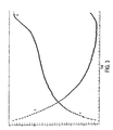
- Battery pack 10 is connected to a charger 20.
- Battery pack 10 comprises a plurality of battery cells 11 connected in series, which dictate the voltage and storage capacity for battery pack 10.
- Battery pack 10 includes three battery contacts: first battery contact 12, second battery contact 14, and third battery contact 13.
- Battery contact 12 is the B+ (positive) terminal for battery pack 10.
- Battery contact 14 is the B- or negative/common terminal.
- Battery contact 13 is the S or sensing terminal.
- Battery contacts 12 and 14 receive the charging current sent from the charger 20 (preferably from current source 22, as discussed below) for charging the battery pack 10.
- the battery cells 11 are coupled between the battery contacts 12 and 14.
- a temperature sensing device 15 such as a negative temperature co-efficient (NTC) resistor, or thermistor, R T is typically coupled between battery contacts 13 and 14.
- NTC negative temperature co-efficient
- the temperature sensing device is preferably in closer proximity to the cells 11 for monitoring of the battery temperature.
- Other components, such as capacitors, etc., or circuits can be used to provide a signal representative of the battery temperature.
- the charger 20 preferably comprises a controller 21, which in turn includes positive terminal (B+) 16 and negative (B-) terminal 17, which are coupled to battery pack 10 via battery contacts 12 and 14, respectively.
- the positive terminal may also act as an input, preferably an analog/digital input, in order for the controller 21 to detect the battery voltage.
- the controller 21 may include another input T, preferably an analog/digital input, which is coupled to the temperature sensing device 15 via the third battery contact 13 (S). This allows the controller 21 to monitor the battery temperature.
- Controller 21 includes a microprocessor 23 for controlling the charging and monitoring operations. Controller 21 may control a current source 22 that provides current to battery pack 10. This current may be a fast charging current and/or an equalization current. Current source 22 may be integrated within controller 21.
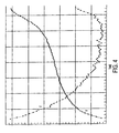
- the battery temperature and voltage varies during the charging process. For example, battery temperature decreases as the battery is charged. The battery temperature then quickly increases as the battery becomes fully charged. However, if the charging process is not stopped when the battery is fully charged, the battery could be overcharged and thus damaged by the rising temperature. Accordingly, battery temperature or battery voltage are usually monitored as indicators of the full charge condition.
- the Saar double inflection termination method described in U.S. Patent Nos. 4,388,582 and 4,392,101 is preferred to detect a battery reaching full charge.
- Other voltage monitoring methods more typically employed are (1) the minus-delta-voltage method, (2) the peak detect method, and (3) the voltage slope detect method.
- the minus-delta-voltage method a sample of the battery peak voltage is stored and compared to the most recent voltage. Termination occurs when the most recent voltage falls below a set point, usually within between 0.5% and 1.0% of the stored peak, or about 10 to 20 millivolts per cell for a NiCd battery.
- the peak detect method is more modern version of the minus-delta-voltage method. Basically, the same method is used, except the set point can be set closer to the peak by using more accurate instrumentation.
- the slope detect method is another voltage monitoring method. According to this method, the voltage peak B is detected by calculating the slope of the voltage curve V, or voltage change rate (dV/dt). Termination occurs when the voltage change rate is 0 or negative.
- Temperature monitoring methods typically employed are (1) absolute temperature termination and (2) temperature change rate (slope) termination.
- Absolute temperature termination relies on the temperature rise that occurs when the battery is fully charged. Under this method, the charging process will be stopped when the battery temperature reaches and/or exceeds a certain temperature.
- the temperature change rate (slope) termination method requires monitoring the slope of the battery temperature over time, or temperature change rate (dT/dt), during the charging process. Termination occurs when the temperature change rate reaches and/or exceeds a predetermined rate. In other words, termination occurs when a trip point is reached and/or exceeded.
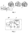
- the charger 20 may accept different battery packs 10, 10', 10", where like numerals refer to like parts.
- Battery packs 10, 10', 10" are similar, but differ in several respects.
- both battery packs 10, 10' receive air blown from charger fan 24 to cool cells 11.
- the temperature sensing device 15 is covered and/or disposed outside of the airflow, so that the airflow does not affect the temperature sensing.
- the temperature sensing device 15 is not covered and/or disposed in of the airflow, so that the airflow affects the temperature sensing.
- Battery pack 10" does not receive any air blown from charger fan 24. Accordingly, the temperature sensing device 15 cannot be affected by blown air.
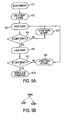
- FIG. 4 shows the temperature/voltage curves T and V, respectively, when battery pack 10' is charged, as opposed to the temperature/voltage curves for battery packs 10, 10", shown in FIG. 3.
- US-A-5391974 describes a battery charging apparatus incorporating an analogue differential circuit and a temperature detection unit, whereby the output from the temperature detection urit is measured at a predetermined time tc, and then again at a later time, to provide a difference in temperature over time. When the calculated difference in temperature over time exceeds a certain threshold value, the charging of the battery is disabled.
- a method for charging a battery comprising: providing a current to the battery; sensing first and second battery temperatures; determining a first temperature change rate between the first and second battery temperatures; characterised by the steps of: sensing a third battery temperature; determining a second temperature change between the second and third battery temperatures; and disabling termination of the charging method based on a temperature-based scheme if the first temperature change rate is equal to or exceeds a first predetermined threshold and the second temperature change rate is less than the first temperature change rate.
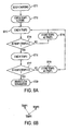
- FIG. 5A is a flowchart of the different steps comprised in a first embodiment of the proposed method.
- the first step (ST1) is to begin the charging process by sending current to battery pack 10.
- the controller 21, via its inputs, may sense the initial battery pack temperature (TEMP1) and store it (ST2).
- the controller 21 then continues to sense the battery temperature (TEMP2) (ST3).
- the controller 21 compares the battery temperature TEMP2 with the initial battery temperature TEMP1 to determine whether the difference (TEMP2-TEMP1) is higher than, equal to, or lower than a predetermined threshold X (ST4).
- TEMP2 battery temperature
- TEMP1 initial battery temperature
- X predetermined threshold
- the predetermined threshold X for NiCd batteries is preferably equal to or higher than zero A/D counts.
- an A/D count may vary by the resolution of, the number of bits of, and/or the conversion range for the A/D converter in controller 21. Nevertheless, persons skilled in the art shall recognize that controller 21 is checking whether the battery temperature has remained the same or has increased between TEMP1 and TEMP2 (see FIG. 5B).
- the predetermined threshold X is equal to about 0.038° Celsius.
- the controller 21 will store TEMP2 as TEMP1 (ST5) and sense a new battery temperature TEMP2 (ST3).
- controller 21 senses again the battery temperature (TEMP3) (ST6). The controller 21 then compares the battery temperatures TEMP2 and TEMP3 to determine whether the difference (TEMP2-TEMP3) is higher than, equal to, or lower than a predetermined threshold Y (ST7).
- TEMP3 battery temperature
- the predetermined threshold Y for NiCd batteries is preferably equal to or higher than one A/D count.
- controller 21 is checking whether the battery temperature has remained the same or has decreased between TEMP2 and TEMP3 (see FIG. 5B).
- the predetermined threshold Y is equal to about 0.077° Celsius.
- the controller 21 will store TEMP3 as TEMP1 (ST9) and sense a new battery temperature TEMP2 (ST3).
- the controller 21 then disables the temperature change rate termination scheme (ST10).
- the controller 21 may also disable any other temperature-based charging, such as the absolute temperature method. Effectively, such double-stage scheme would prevent disablement of the temperature-based charging termination schemes if the battery temperature remains constant and/or continues to increase, i.e., the typical temperature curve when the battery pack is reaching full charge (see FIG. 3).
- comparison steps ST4 and ST7 can be defined in the logical opposite to achieve the same result.
- controller 21 can check whether the difference between TEMP2 and TEMP1 (TEMP2-TEMP1) is equal to and/or higher than threshold X
- controller 21 can check whether the difference between TEMP1 and TEMP2 (TEMP1-TEMP2) is equal to and/or lower than a predetermined threshold X'.
- threshold X' may be equal to or lower than threshold X.
- controller 21 can check whether the difference between TEMP2 and TEMP3 (TEMP2-TEMP3) is equal to and/or higher than threshold X, controller 21 can check whether the difference between TEMP3 and TEMP2 (TEMP3-TEMP2) is equal to and/or lower than a predetermined threshold Y'.
- threshold Y' may be equal to or lower than threshold Y.
- FIG. 6B is a flowchart of the different steps comprised in a second embodiment of the proposed method, where the teachings found in the embodiment described above is herein incorporated by reference.
- the first step (ST11) is to begin the charging process by sending current to battery pack 10.
- the controller 21, via its inputs, may sense the initial battery pack temperature (TEMP1) and store it (ST12).
- TMP1 initial battery pack temperature
- the controller 21 then continues to sense the battery temperature (TEMP2) (ST13).
- the controller 21 compares the initial battery temperature TEMP1 with the battery temperature TEMP2 to determine whether the difference (TEMP1-TEMP2) is higher than, equal to, or lower than a predetermined threshold Z (ST14).
- TEMP1-TEMP2 the battery temperature
- controller 21 is effectively determining the temperature change rate.
- the predetermined threshold Z for NiCd batteries is preferably equal to or higher than zero A/D counts.
- controller 21 is checking whether the battery temperature has remained the same or has decreased between TEMP1 and TEMP2 (see FIG. 6B).
- the predetermined threshold Z is equal to about 0.038° Celsius.
- the controller 21 will store TEMP2 as TEMP1 (ST15) and sense a new battery temperature TEMP2 (ST13).
- controller 21 senses again the battery temperature (TEMP3) (ST16). The controller 21 then compares the battery temperatures TEMP3 and TEMP2 to determine whether the difference (TEMP3-TEMP2) is higher than, equal to, or lower than a predetermined threshold A (ST17). Persons skilled in the art shall recognize that controller 21 is effectively determining the temperature change rate.
- the predetermined threshold A for NiCd batteries is preferably equal to or higher than one A/D count.
- controller 21 is checking whether the battery temperature has remained the same or has increased between TEMP2 and TEMP3 (see FIG. 6B).
- the predetermined threshold A is equal to about 0.077° Celsius.
- the controller 21 will store TEMP3 as TEMP1 (ST19) and sense a new battery temperature TEMP2 (ST13).
- the controller 21 disables the temperature change rate termination scheme (ST20).
- the controller 21 may also disable any other temperature-based charging, such as the absolute temperature method. Effectively, such double-stage scheme would prevent disablement of the temperature-based charging termination schemes if the battery temperature remains constant and/or continues to decrease, i.e., the typical temperature curve at the beginning of the charging process (see FIG. 3).
- comparison steps ST14 and ST17 can be defined in the logical opposite to achieve the same result.
- controller 21 can check whether the difference between TEMP1 and TEMP2 (TEMP1-TEMP2) is equal to and/or higher than threshold Z
- controller 21 can check whether the difference between TEMP2 and TEMP1 (TEMP2-TEMP1) is equal to and/or lower than a predetermined threshold Z'.
- threshold Z' may be equal to or lower than threshold Z.
- controller 21 can check whether the difference between TEMP3 and TEMP2 (TEMP3-TEMP2) is equal to and/or higher than threshold A, controller 21 can check whether the difference between TEMP2 and TEMP3 (TEMP2-TEMP3) is equal to and/or lower than a predetermined threshold A'.
- threshold A' may be equal to or lower than threshold A.
Abstract
Description
- This invention relates generally to a method and apparatus for charging rechargeable batteries.
- The several advantages of cordless power for portable power tools and certain kitchen and domestic appliances have led to the development of a wide range of sizes of power- or battery-packs, that is, a contained group of power cells. These power cells may include nickel cadmium (NiCd), nickel metal hydride (NiMH), lithium, or lead-acid cells, etc.
- Referring to FIGS. 1-2, a
typcial battery pack 10 is connected to acharger 20.Battery pack 10 comprises a plurality ofbattery cells 11 connected in series, which dictate the voltage and storage capacity forbattery pack 10.Battery pack 10 includes three battery contacts: first battery contact 12, second battery contact 14, and third battery contact 13. - Battery contact 12 is the B+ (positive) terminal for
battery pack 10. Battery contact 14 is the B- or negative/common terminal. Battery contact 13 is the S or sensing terminal. Battery contacts 12 and 14 receive the charging current sent from the charger 20 (preferably fromcurrent source 22, as discussed below) for charging thebattery pack 10. - As shown in FIG. 2, the
battery cells 11 are coupled between the battery contacts 12 and 14. In addition, atemperature sensing device 15, such as a negative temperature co-efficient (NTC) resistor, or thermistor, RT is typically coupled between battery contacts 13 and 14. The temperature sensing device is preferably in closer proximity to thecells 11 for monitoring of the battery temperature. Other components, such as capacitors, etc., or circuits can be used to provide a signal representative of the battery temperature. - The
charger 20 preferably comprises acontroller 21, which in turn includes positive terminal (B+) 16 and negative (B-)terminal 17, which are coupled tobattery pack 10 via battery contacts 12 and 14, respectively. The positive terminal may also act as an input, preferably an analog/digital input, in order for thecontroller 21 to detect the battery voltage. In addition, thecontroller 21 may include another input T, preferably an analog/digital input, which is coupled to thetemperature sensing device 15 via the third battery contact 13 (S). This allows thecontroller 21 to monitor the battery temperature.Controller 21 includes a microprocessor 23 for controlling the charging and monitoring operations.Controller 21 may control acurrent source 22 that provides current tobattery pack 10. This current may be a fast charging current and/or an equalization current.Current source 22 may be integrated withincontroller 21. - Referring to FIG. 3, the battery temperature and voltage varies during the charging process. For example, battery temperature decreases as the battery is charged. The battery temperature then quickly increases as the battery becomes fully charged. However, if the charging process is not stopped when the battery is fully charged, the battery could be overcharged and thus damaged by the rising temperature. Accordingly, battery temperature or battery voltage are usually monitored as indicators of the full charge condition.
- Among the voltage monitoring methods, the Saar double inflection termination method described in U.S. Patent Nos. 4,388,582 and 4,392,101, is preferred to detect a battery reaching full charge. Other voltage monitoring methods more typically employed are (1) the minus-delta-voltage method, (2) the peak detect method, and (3) the voltage slope detect method. In the minus-delta-voltage method, a sample of the battery peak voltage is stored and compared to the most recent voltage. Termination occurs when the most recent voltage falls below a set point, usually within between 0.5% and 1.0% of the stored peak, or about 10 to 20 millivolts per cell for a NiCd battery.
- The peak detect method is more modern version of the minus-delta-voltage method. Basically, the same method is used, except the set point can be set closer to the peak by using more accurate instrumentation.
- The slope detect method is another voltage monitoring method. According to this method, the voltage peak B is detected by calculating the slope of the voltage curve V, or voltage change rate (dV/dt). Termination occurs when the voltage change rate is 0 or negative.
- Temperature monitoring methods typically employed are (1) absolute temperature termination and (2) temperature change rate (slope) termination. Absolute temperature termination relies on the temperature rise that occurs when the battery is fully charged. Under this method, the charging process will be stopped when the battery temperature reaches and/or exceeds a certain temperature.
- The temperature change rate (slope) termination method requires monitoring the slope of the battery temperature over time, or temperature change rate (dT/dt), during the charging process. Termination occurs when the temperature change rate reaches and/or exceeds a predetermined rate. In other words, termination occurs when a trip point is reached and/or exceeded.
- Referring to FIGS. 1-2, the
charger 20 may acceptdifferent battery packs Battery packs battery packs 10, 10' receive air blown fromcharger fan 24 to coolcells 11. Inbattery pack 10, thetemperature sensing device 15 is covered and/or disposed outside of the airflow, so that the airflow does not affect the temperature sensing. On the other hand, in battery pack 10', thetemperature sensing device 15 is not covered and/or disposed in of the airflow, so that the airflow affects the temperature sensing.Battery pack 10" does not receive any air blown fromcharger fan 24. Accordingly, thetemperature sensing device 15 cannot be affected by blown air. - FIG. 4 shows the temperature/voltage curves T and V, respectively, when battery pack 10' is charged, as opposed to the temperature/voltage curves for
battery packs - US-A-5391974 describes a battery charging apparatus incorporating an analogue differential circuit and a temperature detection unit, whereby the output from the temperature detection urit is measured at a predetermined time tc, and then again at a later time, to provide a difference in temperature over time. When the calculated difference in temperature over time exceeds a certain threshold value, the charging of the battery is disabled.
- It is an object of the invention to provide a charging and monitoring method that will not result in undercharged batteries.
- In accordance with the present invention, there is provided a method for charging a battery comprising: providing a current to the battery; sensing first and second battery temperatures; determining a first temperature change rate between the first and second battery temperatures; characterised by the steps of: sensing a third battery temperature; determining a second temperature change between the second and third battery temperatures; and disabling termination of the charging method based on a temperature-based scheme if the first temperature change rate is equal to or exceeds a first predetermined threshold and the second temperature change rate is less than the first temperature change rate.
- Additional features and benefits of the present invention are described, and will be apparent from, the accompanying drawings and the detailed description below.
- The accompanying drawings illustrate preferred embodiments of the invention according to the practical application of the principles thereof, and in which:
- FIG. 1 shows a charger that accepts different types of battery packs;
- FIG. 2 is a circuit schematic diagram of a battery charger;
- FIG. 3 is a graph showing the voltage and temperature curves for battery packs that are not affected by airflow;
- FIG. 4 is a graph showing the voltage and temperature curves for battery packs that are affected by airflow;
- FIG. 5 illustrates a first embodiment of the charging process according to the present invention, where FIG. 5A illustrates a flowchart of the first embodiment of the charging process, and FIG. 5B illustrates a portion of the temperature curve; and
- FIG. 6 illustrates a second embodiment of the charging process according to the present invention, where FIG. 6A illustrates a flowchart of the second embodiment of the charging process, and FIG. 6B illustrates a portion of the temperature curve.
-
- The invention is now described with reference to the accompanying figures, wherein like numerals designate like parts.
- Persons skilled in the art should recognize that the methods disclosed below can be implemented with the
charger 20 shown in FIGS. 1-2, preferably via thecontroller 21 and/or the processor 23. In other words, persons skilled in the art shall recognize that, while the discussion below refers to controlling 21 performing different steps, such steps can be carried out by the processor 23 or any other circuitry incharger 20. - FIG. 5A is a flowchart of the different steps comprised in a first embodiment of the proposed method. The first step (ST1) is to begin the charging process by sending current to
battery pack 10. Thecontroller 21, via its inputs, may sense the initial battery pack temperature (TEMP1) and store it (ST2). - The
controller 21 then continues to sense the battery temperature (TEMP2) (ST3). Thecontroller 21 then compares the battery temperature TEMP2 with the initial battery temperature TEMP1 to determine whether the difference (TEMP2-TEMP1) is higher than, equal to, or lower than a predetermined threshold X (ST4). Persons skilled in the art shall recognize thatcontroller 21 is effectively determining the temperature change rate. - The predetermined threshold X for NiCd batteries is preferably equal to or higher than zero A/D counts. Persons skilled in the art shall recognize that an A/D count may vary by the resolution of, the number of bits of, and/or the conversion range for the A/D converter in
controller 21. Nevertheless, persons skilled in the art shall recognize thatcontroller 21 is checking whether the battery temperature has remained the same or has increased between TEMP1 and TEMP2 (see FIG. 5B). Preferably, the predetermined threshold X is equal to about 0.038° Celsius. - If the difference between TEMP2 and TEMP1 (TEMP2-TEMP1) is below threshold X, the
controller 21 will store TEMP2 as TEMP1 (ST5) and sense a new battery temperature TEMP2 (ST3). - If the difference between TEMP2 and TEMP1 (TEMP2-TEMP1) is equal to and/or higher than threshold X,
controller 21 senses again the battery temperature (TEMP3) (ST6). Thecontroller 21 then compares the battery temperatures TEMP2 and TEMP3 to determine whether the difference (TEMP2-TEMP3) is higher than, equal to, or lower than a predetermined threshold Y (ST7). Persons skilled in the art shall recognize thatcontroller 21 is effectively determining the temperature change rate. - The predetermined threshold Y for NiCd batteries is preferably equal to or higher than one A/D count. Persons skilled in the art shall recognize that
controller 21 is checking whether the battery temperature has remained the same or has decreased between TEMP2 and TEMP3 (see FIG. 5B). Preferably, the predetermined threshold Y is equal to about 0.077° Celsius. - If the difference between TEMP2 and TEMP3 (TEMP2-TEMP3) is below threshold Y, the
controller 21 will store TEMP3 as TEMP1 (ST9) and sense a new battery temperature TEMP2 (ST3). - If the difference between TEMP2 and TEMP3 (TEMP2-TEMP3) is equal to and/or higher than threshold Y, the
controller 21 then disables the temperature change rate termination scheme (ST10). Alternatively, thecontroller 21 may also disable any other temperature-based charging, such as the absolute temperature method. Effectively, such double-stage scheme would prevent disablement of the temperature-based charging termination schemes if the battery temperature remains constant and/or continues to increase, i.e., the typical temperature curve when the battery pack is reaching full charge (see FIG. 3). - Persons skilled in the art shall recognize that the comparison steps ST4 and ST7 can be defined in the logical opposite to achieve the same result. In other words, rather than checking whether the difference between TEMP2 and TEMP1 (TEMP2-TEMP1) is equal to and/or higher than threshold X,
controller 21 can check whether the difference between TEMP1 and TEMP2 (TEMP1-TEMP2) is equal to and/or lower than a predetermined threshold X'. Persons skilled in the art will recognize that threshold X' may be equal to or lower than threshold X. - Similarly, rather than checking whether the difference between TEMP2 and TEMP3 (TEMP2-TEMP3) is equal to and/or higher than threshold X,
controller 21 can check whether the difference between TEMP3 and TEMP2 (TEMP3-TEMP2) is equal to and/or lower than a predetermined threshold Y'. Persons skilled in the art will recognize that threshold Y' may be equal to or lower than threshold Y. - FIG. 6B is a flowchart of the different steps comprised in a second embodiment of the proposed method, where the teachings found in the embodiment described above is herein incorporated by reference. The first step (ST11) is to begin the charging process by sending current to
battery pack 10. Thecontroller 21, via its inputs, may sense the initial battery pack temperature (TEMP1) and store it (ST12). - The
controller 21 then continues to sense the battery temperature (TEMP2) (ST13). Thecontroller 21 then compares the initial battery temperature TEMP1 with the battery temperature TEMP2 to determine whether the difference (TEMP1-TEMP2) is higher than, equal to, or lower than a predetermined threshold Z (ST14). Persons skilled in the art shall recognize thatcontroller 21 is effectively determining the temperature change rate. - The predetermined threshold Z for NiCd batteries is preferably equal to or higher than zero A/D counts. Persons skilled in the art shall recognize that
controller 21 is checking whether the battery temperature has remained the same or has decreased between TEMP1 and TEMP2 (see FIG. 6B). Preferably, the predetermined threshold Z is equal to about 0.038° Celsius. - If the difference between TEMP1 and TEMP2 (TEMP1-TEMP2) is below threshold Z, the
controller 21 will store TEMP2 as TEMP1 (ST15) and sense a new battery temperature TEMP2 (ST13). - If the difference between TEMP1 and TEMP2 (TEMP1-TEMP2) is equal to and/or higher than threshold Z,
controller 21 senses again the battery temperature (TEMP3) (ST16). Thecontroller 21 then compares the battery temperatures TEMP3 and TEMP2 to determine whether the difference (TEMP3-TEMP2) is higher than, equal to, or lower than a predetermined threshold A (ST17). Persons skilled in the art shall recognize thatcontroller 21 is effectively determining the temperature change rate. - The predetermined threshold A for NiCd batteries is preferably equal to or higher than one A/D count. Persons skilled in the art shall recognize that
controller 21 is checking whether the battery temperature has remained the same or has increased between TEMP2 and TEMP3 (see FIG. 6B). Preferably, the predetermined threshold A is equal to about 0.077° Celsius. - If the difference between TEMP3 and TEMP2 (TEMP3-TEMP2) is below threshold A, the
controller 21 will store TEMP3 as TEMP1 (ST19) and sense a new battery temperature TEMP2 (ST13). - If the difference between TEMP3 and TEMP2 (TEMP3-TEMP2) is equal to and/or higher than threshold A, the
controller 21 disables the temperature change rate termination scheme (ST20). Alternatively, thecontroller 21 may also disable any other temperature-based charging, such as the absolute temperature method. Effectively, such double-stage scheme would prevent disablement of the temperature-based charging termination schemes if the battery temperature remains constant and/or continues to decrease, i.e., the typical temperature curve at the beginning of the charging process (see FIG. 3). - Persons skilled in the art shall recognize that the comparison steps ST14 and ST17 can be defined in the logical opposite to achieve the same result. In other words, rather than checking whether the difference between TEMP1 and TEMP2 (TEMP1-TEMP2) is equal to and/or higher than threshold Z,
controller 21 can check whether the difference between TEMP2 and TEMP1 (TEMP2-TEMP1) is equal to and/or lower than a predetermined threshold Z'. Persons skilled in the art will recognize that threshold Z' may be equal to or lower than threshold Z. - Similarly, rather than checking whether the difference between TEMP3 and TEMP2 (TEMP3-TEMP2) is equal to and/or higher than threshold A,
controller 21 can check whether the difference between TEMP2 and TEMP3 (TEMP2-TEMP3) is equal to and/or lower than a predetermined threshold A'. Persons skilled in the art will recognize that threshold A' may be equal to or lower than threshold A. - Persons skilled in the art shall also recognize that the different embodiments can be executed independently, sequentially or simultaneously.
- Persons skilled in the art may recognize other alternatives or additions to the means or steps disclosed herein. However, all these additions and/or alterations are considered to be equivalents of the present invention, as defined in the appended claims.
Claims (6)
- A method for charging a battery comprising:providing a current to the battery;sensing first and second battery temperatures;determining a first temperature change rate between the first and second battery temperatures; characterized by the steps of :sensing a third battery temperature;determining a second temperature change between the second and third battery temperatures; anddisabling termination of the charging method based on a temperature-based scheme if the first temperature change rate is equal to or exceeds a first predetermined threshold and the second temperature change rate is less than the first temperature change rate.
- The method of Claim 1, wherein at least one battery temperature is sensed by means of a thermistor.
- The method of Claim 2, wherein the thermistor is outside of an airflow.
- The method of Claim 2, wherein the thermistor is inside an airflow.
- The method of Claim 1, wherein the first predetermined threshold is about 0.038° Celsius.
- The method of Claim 1, wherein the temperature-based scheme is a temperature change rate termination scheme or an absolute temperature scheme.
Applications Claiming Priority (4)
| Application Number | Priority Date | Filing Date | Title |
|---|---|---|---|
| US29385901P | 2001-05-25 | 2001-05-25 | |
| US293859P | 2001-05-25 | ||
| US126568 | 2002-04-19 | ||
| US10/126,568 US6489752B1 (en) | 2001-05-25 | 2002-04-19 | Method and apparatus for charging batteries |
Publications (3)
| Publication Number | Publication Date |
|---|---|
| EP1261098A2 EP1261098A2 (en) | 2002-11-27 |
| EP1261098A3 EP1261098A3 (en) | 2004-02-11 |
| EP1261098B1 true EP1261098B1 (en) | 2005-08-03 |
Family
ID=26824813
Family Applications (1)
| Application Number | Title | Priority Date | Filing Date |
|---|---|---|---|
| EP02011041A Expired - Lifetime EP1261098B1 (en) | 2001-05-25 | 2002-05-17 | Method and apparatus for charging batteries |
Country Status (6)
| Country | Link |
|---|---|
| US (1) | US6489752B1 (en) |
| EP (1) | EP1261098B1 (en) |
| JP (1) | JP4008754B2 (en) |
| AT (1) | ATE301341T1 (en) |
| DE (1) | DE60205306T2 (en) |
| ES (1) | ES2243620T3 (en) |
Families Citing this family (13)
| Publication number | Priority date | Publication date | Assignee | Title |
|---|---|---|---|---|
| US7425816B2 (en) * | 2002-11-22 | 2008-09-16 | Milwaukee Electric Tool Corporation | Method and system for pulse charging of a lithium-based battery |
| US7157882B2 (en) | 2002-11-22 | 2007-01-02 | Milwaukee Electric Tool Corporation | Method and system for battery protection employing a selectively-actuated switch |
| US7176654B2 (en) | 2002-11-22 | 2007-02-13 | Milwaukee Electric Tool Corporation | Method and system of charging multi-cell lithium-based batteries |
| US8471532B2 (en) | 2002-11-22 | 2013-06-25 | Milwaukee Electric Tool Corporation | Battery pack |
| US7589500B2 (en) | 2002-11-22 | 2009-09-15 | Milwaukee Electric Tool Corporation | Method and system for battery protection |
| US7145314B2 (en) * | 2003-05-23 | 2006-12-05 | Hitachi Koki Co., Ltd. | DC power source unit with battery charging function |
| TW200503305A (en) | 2003-07-03 | 2005-01-16 | Ray O Vac Corp | Method and apparatus for regulating charging of electrochemical cells using cell temperature increase rate |
| US7705565B2 (en) * | 2003-12-31 | 2010-04-27 | Motorola, Inc. | Method and system for wireless charging |
| US9569957B2 (en) * | 2012-03-08 | 2017-02-14 | Htc Corporation | Systems, devices and methods involving device identification |
| JP5954144B2 (en) * | 2012-11-30 | 2016-07-20 | ソニー株式会社 | Control device, control method, control system, and electric vehicle |
| US10712805B2 (en) | 2018-03-05 | 2020-07-14 | Dell Products L.P. | System and method of thermal management of information handling systems |
| US10666078B2 (en) * | 2018-07-16 | 2020-05-26 | Dell Products L.P. | System and method of managing battery systems |
| CN112622690A (en) * | 2020-11-09 | 2021-04-09 | 特瓦特能源科技有限公司 | Monitoring method and system for power battery safe charging |
Family Cites Families (6)
| Publication number | Priority date | Publication date | Assignee | Title |
|---|---|---|---|---|
| US4392101A (en) * | 1978-05-31 | 1983-07-05 | Black & Decker Inc. | Method of charging batteries and apparatus therefor |
| US4388582A (en) * | 1978-05-31 | 1983-06-14 | Black & Decker Inc. | Apparatus and method for charging batteries |
| US5391974A (en) * | 1990-10-15 | 1995-02-21 | Toshiba Battery Co., Ltd. | Secondary battery charging circuit |
| US5637982A (en) * | 1991-06-17 | 1997-06-10 | Kabushiki Kaisha Toshiba | Method and system for detecting full charge of a rechargeable battery in a portable computer system |
| US5711605A (en) * | 1996-03-12 | 1998-01-27 | Globe-Union, Inc. | Method and apparatus for predicting battery temperature |
| US6455186B1 (en) * | 1998-03-05 | 2002-09-24 | Black & Decker Inc. | Battery cooling system |
-
2002
- 2002-04-19 US US10/126,568 patent/US6489752B1/en not_active Expired - Fee Related
- 2002-05-17 ES ES02011041T patent/ES2243620T3/en not_active Expired - Lifetime
- 2002-05-17 AT AT02011041T patent/ATE301341T1/en not_active IP Right Cessation
- 2002-05-17 DE DE60205306T patent/DE60205306T2/en not_active Expired - Lifetime
- 2002-05-17 EP EP02011041A patent/EP1261098B1/en not_active Expired - Lifetime
- 2002-05-23 JP JP2002149225A patent/JP4008754B2/en not_active Expired - Fee Related
Also Published As
| Publication number | Publication date |
|---|---|
| US20020175658A1 (en) | 2002-11-28 |
| EP1261098A2 (en) | 2002-11-27 |
| ES2243620T3 (en) | 2005-12-01 |
| US6489752B1 (en) | 2002-12-03 |
| ATE301341T1 (en) | 2005-08-15 |
| JP4008754B2 (en) | 2007-11-14 |
| EP1261098A3 (en) | 2004-02-11 |
| DE60205306T2 (en) | 2006-06-01 |
| DE60205306D1 (en) | 2005-09-08 |
| JP2003092842A (en) | 2003-03-28 |
Similar Documents
| Publication | Publication Date | Title |
|---|---|---|
| US6172487B1 (en) | Method and apparatus for charging batteries | |
| US8148950B2 (en) | Charging method | |
| TWI425737B (en) | Charging apparatus and charging method | |
| US6850041B2 (en) | Battery pack used as power source for portable device | |
| CA2148699C (en) | Fast battery charging method and apparatus with temperature gradient detection | |
| US20070075678A1 (en) | Life cycle extending batteries and battery charging means, method and apparatus | |
| EP1261098B1 (en) | Method and apparatus for charging batteries | |
| JPH06315233A (en) | Battery charge control method | |
| US6008628A (en) | Method for charging batteries | |
| US20090295335A1 (en) | Battery pack and charging method for the same | |
| GB2317510A (en) | Temperature responsive battery charger | |
| US5329219A (en) | Method and apparatus for charging a battery | |
| US6133713A (en) | Method for charging batteries | |
| US6380717B2 (en) | Device and method for controlling charging of secondary battery | |
| US20080174263A1 (en) | Battery charger for different capacity cells | |
| US20040130294A1 (en) | Life cycle extending batteries and battery charging means, methods and apparatus | |
| WO1999050948A1 (en) | Rechargeable battery having overcharge protection circuit and method of charging rechargeable battery | |
| JP3774995B2 (en) | Lithium ion secondary battery charging method and charging device therefor | |
| JPH07284235A (en) | Charging apparatus and residual charge detector | |
| JP3029664B2 (en) | Battery powered personal computer | |
| JPH1032020A (en) | Charge and discharge control method for sealed type lead-acid battery | |
| JPH04267078A (en) | Combined battery and charging method thereof | |
| JP2928439B2 (en) | Secondary battery charge detection method and device | |
| JP3144394B2 (en) | Charging device and charging method | |
| JP3346821B2 (en) | Charging device |
Legal Events
| Date | Code | Title | Description |
|---|---|---|---|
| PUAI | Public reference made under article 153(3) epc to a published international application that has entered the european phase |
Free format text: ORIGINAL CODE: 0009012 |
|
| AK | Designated contracting states |
Kind code of ref document: A2 Designated state(s): AT BE CH CY DE DK ES FI FR GB GR IE IT LI LU MC NL PT SE TR |
|
| AX | Request for extension of the european patent |
Free format text: AL;LT;LV;MK;RO;SI |
|
| PUAL | Search report despatched |
Free format text: ORIGINAL CODE: 0009013 |
|
| AK | Designated contracting states |
Kind code of ref document: A3 Designated state(s): AT BE CH CY DE DK ES FI FR GB GR IE IT LI LU MC NL PT SE TR |
|
| AX | Request for extension of the european patent |
Extension state: AL LT LV MK RO SI |
|
| RIN1 | Information on inventor provided before grant (corrected) |
Inventor name: WATTS, FRED S Inventor name: TRINH, DANH T. |
|
| 17P | Request for examination filed |
Effective date: 20040503 |
|
| 17Q | First examination report despatched |
Effective date: 20040607 |
|
| AKX | Designation fees paid |
Designated state(s): AT BE CH CY DE DK ES FI FR GB GR IE IT LI LU MC NL PT SE TR |
|
| GRAP | Despatch of communication of intention to grant a patent |
Free format text: ORIGINAL CODE: EPIDOSNIGR1 |
|
| GRAS | Grant fee paid |
Free format text: ORIGINAL CODE: EPIDOSNIGR3 |
|
| GRAA | (expected) grant |
Free format text: ORIGINAL CODE: 0009210 |
|
| AK | Designated contracting states |
Kind code of ref document: B1 Designated state(s): AT BE CH CY DE DK ES FI FR GB GR IE IT LI LU MC NL PT SE TR |
|
| PG25 | Lapsed in a contracting state [announced via postgrant information from national office to epo] |
Ref country code: NL Free format text: LAPSE BECAUSE OF FAILURE TO SUBMIT A TRANSLATION OF THE DESCRIPTION OR TO PAY THE FEE WITHIN THE PRESCRIBED TIME-LIMIT Effective date: 20050803 Ref country code: AT Free format text: LAPSE BECAUSE OF FAILURE TO SUBMIT A TRANSLATION OF THE DESCRIPTION OR TO PAY THE FEE WITHIN THE PRESCRIBED TIME-LIMIT Effective date: 20050803 Ref country code: BE Free format text: LAPSE BECAUSE OF FAILURE TO SUBMIT A TRANSLATION OF THE DESCRIPTION OR TO PAY THE FEE WITHIN THE PRESCRIBED TIME-LIMIT Effective date: 20050803 Ref country code: CH Free format text: LAPSE BECAUSE OF FAILURE TO SUBMIT A TRANSLATION OF THE DESCRIPTION OR TO PAY THE FEE WITHIN THE PRESCRIBED TIME-LIMIT Effective date: 20050803 Ref country code: FI Free format text: LAPSE BECAUSE OF FAILURE TO SUBMIT A TRANSLATION OF THE DESCRIPTION OR TO PAY THE FEE WITHIN THE PRESCRIBED TIME-LIMIT Effective date: 20050803 Ref country code: TR Free format text: LAPSE BECAUSE OF FAILURE TO SUBMIT A TRANSLATION OF THE DESCRIPTION OR TO PAY THE FEE WITHIN THE PRESCRIBED TIME-LIMIT Effective date: 20050803 Ref country code: LI Free format text: LAPSE BECAUSE OF FAILURE TO SUBMIT A TRANSLATION OF THE DESCRIPTION OR TO PAY THE FEE WITHIN THE PRESCRIBED TIME-LIMIT Effective date: 20050803 |
|
| REG | Reference to a national code |
Ref country code: GB Ref legal event code: FG4D |
|
| REG | Reference to a national code |
Ref country code: CH Ref legal event code: EP |
|
| REG | Reference to a national code |
Ref country code: IE Ref legal event code: FG4D |
|
| REF | Corresponds to: |
Ref document number: 60205306 Country of ref document: DE Date of ref document: 20050908 Kind code of ref document: P |
|
| PG25 | Lapsed in a contracting state [announced via postgrant information from national office to epo] |
Ref country code: GR Free format text: LAPSE BECAUSE OF FAILURE TO SUBMIT A TRANSLATION OF THE DESCRIPTION OR TO PAY THE FEE WITHIN THE PRESCRIBED TIME-LIMIT Effective date: 20051103 Ref country code: DK Free format text: LAPSE BECAUSE OF FAILURE TO SUBMIT A TRANSLATION OF THE DESCRIPTION OR TO PAY THE FEE WITHIN THE PRESCRIBED TIME-LIMIT Effective date: 20051103 |
|
| REG | Reference to a national code |
Ref country code: SE Ref legal event code: TRGR |
|
| REG | Reference to a national code |
Ref country code: ES Ref legal event code: FG2A Ref document number: 2243620 Country of ref document: ES Kind code of ref document: T3 |
|
| PG25 | Lapsed in a contracting state [announced via postgrant information from national office to epo] |
Ref country code: PT Free format text: LAPSE BECAUSE OF FAILURE TO SUBMIT A TRANSLATION OF THE DESCRIPTION OR TO PAY THE FEE WITHIN THE PRESCRIBED TIME-LIMIT Effective date: 20060103 |
|
| NLV1 | Nl: lapsed or annulled due to failure to fulfill the requirements of art. 29p and 29m of the patents act | ||
| REG | Reference to a national code |
Ref country code: CH Ref legal event code: PL |
|
| ET | Fr: translation filed | ||
| PG25 | Lapsed in a contracting state [announced via postgrant information from national office to epo] |
Ref country code: IE Free format text: LAPSE BECAUSE OF NON-PAYMENT OF DUE FEES Effective date: 20060517 |
|
| PG25 | Lapsed in a contracting state [announced via postgrant information from national office to epo] |
Ref country code: MC Free format text: LAPSE BECAUSE OF NON-PAYMENT OF DUE FEES Effective date: 20060531 |
|
| PLBE | No opposition filed within time limit |
Free format text: ORIGINAL CODE: 0009261 |
|
| STAA | Information on the status of an ep patent application or granted ep patent |
Free format text: STATUS: NO OPPOSITION FILED WITHIN TIME LIMIT |
|
| 26N | No opposition filed |
Effective date: 20060504 |
|
| REG | Reference to a national code |
Ref country code: IE Ref legal event code: MM4A |
|
| PG25 | Lapsed in a contracting state [announced via postgrant information from national office to epo] |
Ref country code: LU Free format text: LAPSE BECAUSE OF NON-PAYMENT OF DUE FEES Effective date: 20060517 |
|
| PGFP | Annual fee paid to national office [announced via postgrant information from national office to epo] |
Ref country code: ES Payment date: 20080526 Year of fee payment: 7 |
|
| PGFP | Annual fee paid to national office [announced via postgrant information from national office to epo] |
Ref country code: IT Payment date: 20080527 Year of fee payment: 7 |
|
| PGFP | Annual fee paid to national office [announced via postgrant information from national office to epo] |
Ref country code: SE Payment date: 20080529 Year of fee payment: 7 |
|
| PG25 | Lapsed in a contracting state [announced via postgrant information from national office to epo] |
Ref country code: CY Free format text: LAPSE BECAUSE OF FAILURE TO SUBMIT A TRANSLATION OF THE DESCRIPTION OR TO PAY THE FEE WITHIN THE PRESCRIBED TIME-LIMIT Effective date: 20050803 |
|
| REG | Reference to a national code |
Ref country code: FR Ref legal event code: ST Effective date: 20100129 |
|
| PG25 | Lapsed in a contracting state [announced via postgrant information from national office to epo] |
Ref country code: FR Free format text: LAPSE BECAUSE OF NON-PAYMENT OF DUE FEES Effective date: 20090602 |
|
| PGFP | Annual fee paid to national office [announced via postgrant information from national office to epo] |
Ref country code: FR Payment date: 20080519 Year of fee payment: 7 |
|
| REG | Reference to a national code |
Ref country code: ES Ref legal event code: FD2A Effective date: 20090518 |
|
| PG25 | Lapsed in a contracting state [announced via postgrant information from national office to epo] |
Ref country code: ES Free format text: LAPSE BECAUSE OF NON-PAYMENT OF DUE FEES Effective date: 20090518 |
|
| PG25 | Lapsed in a contracting state [announced via postgrant information from national office to epo] |
Ref country code: IT Free format text: LAPSE BECAUSE OF NON-PAYMENT OF DUE FEES Effective date: 20090517 |
|
| PG25 | Lapsed in a contracting state [announced via postgrant information from national office to epo] |
Ref country code: SE Free format text: LAPSE BECAUSE OF NON-PAYMENT OF DUE FEES Effective date: 20090518 |
|
| PGFP | Annual fee paid to national office [announced via postgrant information from national office to epo] |
Ref country code: DE Payment date: 20130530 Year of fee payment: 12 Ref country code: GB Payment date: 20130528 Year of fee payment: 12 |
|
| REG | Reference to a national code |
Ref country code: DE Ref legal event code: R119 Ref document number: 60205306 Country of ref document: DE |
|
| GBPC | Gb: european patent ceased through non-payment of renewal fee |
Effective date: 20140517 |
|
| REG | Reference to a national code |
Ref country code: DE Ref legal event code: R119 Ref document number: 60205306 Country of ref document: DE Effective date: 20141202 |
|
| PG25 | Lapsed in a contracting state [announced via postgrant information from national office to epo] |
Ref country code: DE Free format text: LAPSE BECAUSE OF NON-PAYMENT OF DUE FEES Effective date: 20141202 |
|
| PG25 | Lapsed in a contracting state [announced via postgrant information from national office to epo] |
Ref country code: GB Free format text: LAPSE BECAUSE OF NON-PAYMENT OF DUE FEES Effective date: 20140517 |