US10666078B2 - System and method of managing battery systems - Google Patents
System and method of managing battery systems Download PDFInfo
- Publication number
- US10666078B2 US10666078B2 US16/036,555 US201816036555A US10666078B2 US 10666078 B2 US10666078 B2 US 10666078B2 US 201816036555 A US201816036555 A US 201816036555A US 10666078 B2 US10666078 B2 US 10666078B2
- Authority
- US
- United States
- Prior art keywords
- information handling
- battery system
- handling system
- temperature
- battery
- Prior art date
- Legal status (The legal status is an assumption and is not a legal conclusion. Google has not performed a legal analysis and makes no representation as to the accuracy of the status listed.)
- Active, expires
Links
- 238000000034 method Methods 0.000 title claims abstract description 47
- 230000008859 change Effects 0.000 claims abstract description 69
- 238000009529 body temperature measurement Methods 0.000 claims description 49
- 230000008569 process Effects 0.000 abstract description 21
- 238000003860 storage Methods 0.000 description 19
- 238000012545 processing Methods 0.000 description 18
- 238000007599 discharging Methods 0.000 description 13
- 238000004891 communication Methods 0.000 description 6
- 230000002093 peripheral effect Effects 0.000 description 6
- 230000008901 benefit Effects 0.000 description 4
- 230000008878 coupling Effects 0.000 description 4
- 238000010168 coupling process Methods 0.000 description 4
- 238000005859 coupling reaction Methods 0.000 description 4
- 230000003247 decreasing effect Effects 0.000 description 4
- 230000009977 dual effect Effects 0.000 description 4
- 210000000245 forearm Anatomy 0.000 description 4
- 230000007246 mechanism Effects 0.000 description 4
- 238000005516 engineering process Methods 0.000 description 3
- 238000007726 management method Methods 0.000 description 3
- 238000004519 manufacturing process Methods 0.000 description 3
- 230000001133 acceleration Effects 0.000 description 2
- 238000011960 computer-aided design Methods 0.000 description 2
- 238000013500 data storage Methods 0.000 description 2
- 238000009826 distribution Methods 0.000 description 2
- 239000011521 glass Substances 0.000 description 2
- 230000014759 maintenance of location Effects 0.000 description 2
- 230000003287 optical effect Effects 0.000 description 2
- 230000003190 augmentative effect Effects 0.000 description 1
- 230000005540 biological transmission Effects 0.000 description 1
- 239000000835 fiber Substances 0.000 description 1
- 230000000116 mitigating effect Effects 0.000 description 1
- 238000012986 modification Methods 0.000 description 1
- 230000004048 modification Effects 0.000 description 1
- 238000003032 molecular docking Methods 0.000 description 1
- 230000006855 networking Effects 0.000 description 1
- APTZNLHMIGJTEW-UHFFFAOYSA-N pyraflufen-ethyl Chemical compound C1=C(Cl)C(OCC(=O)OCC)=CC(C=2C(=C(OC(F)F)N(C)N=2)Cl)=C1F APTZNLHMIGJTEW-UHFFFAOYSA-N 0.000 description 1
- 239000007787 solid Substances 0.000 description 1
- 230000003068 static effect Effects 0.000 description 1
- 238000012546 transfer Methods 0.000 description 1
Images


Classifications
-
- H—ELECTRICITY
- H02—GENERATION; CONVERSION OR DISTRIBUTION OF ELECTRIC POWER
- H02J—CIRCUIT ARRANGEMENTS OR SYSTEMS FOR SUPPLYING OR DISTRIBUTING ELECTRIC POWER; SYSTEMS FOR STORING ELECTRIC ENERGY
- H02J7/00—Circuit arrangements for charging or depolarising batteries or for supplying loads from batteries
- H02J7/007—Regulation of charging or discharging current or voltage
-
- G—PHYSICS
- G06—COMPUTING; CALCULATING OR COUNTING
- G06F—ELECTRIC DIGITAL DATA PROCESSING
- G06F1/00—Details not covered by groups G06F3/00 - G06F13/00 and G06F21/00
- G06F1/16—Constructional details or arrangements
- G06F1/1613—Constructional details or arrangements for portable computers
- G06F1/1615—Constructional details or arrangements for portable computers with several enclosures having relative motions, each enclosure supporting at least one I/O or computing function
- G06F1/1616—Constructional details or arrangements for portable computers with several enclosures having relative motions, each enclosure supporting at least one I/O or computing function with folding flat displays, e.g. laptop computers or notebooks having a clamshell configuration, with body parts pivoting to an open position around an axis parallel to the plane they define in closed position
- G06F1/1618—Constructional details or arrangements for portable computers with several enclosures having relative motions, each enclosure supporting at least one I/O or computing function with folding flat displays, e.g. laptop computers or notebooks having a clamshell configuration, with body parts pivoting to an open position around an axis parallel to the plane they define in closed position the display being foldable up to the back of the other housing with a single degree of freedom, e.g. by 360° rotation over the axis defined by the rear edge of the base enclosure
-
- G—PHYSICS
- G06—COMPUTING; CALCULATING OR COUNTING
- G06F—ELECTRIC DIGITAL DATA PROCESSING
- G06F1/00—Details not covered by groups G06F3/00 - G06F13/00 and G06F21/00
- G06F1/16—Constructional details or arrangements
- G06F1/1613—Constructional details or arrangements for portable computers
- G06F1/1633—Constructional details or arrangements of portable computers not specific to the type of enclosures covered by groups G06F1/1615 - G06F1/1626
- G06F1/1635—Details related to the integration of battery packs and other power supplies such as fuel cells or integrated AC adapter
-
- G—PHYSICS
- G06—COMPUTING; CALCULATING OR COUNTING
- G06F—ELECTRIC DIGITAL DATA PROCESSING
- G06F1/00—Details not covered by groups G06F3/00 - G06F13/00 and G06F21/00
- G06F1/16—Constructional details or arrangements
- G06F1/18—Packaging or power distribution
- G06F1/189—Power distribution
-
- G—PHYSICS
- G06—COMPUTING; CALCULATING OR COUNTING
- G06F—ELECTRIC DIGITAL DATA PROCESSING
- G06F1/00—Details not covered by groups G06F3/00 - G06F13/00 and G06F21/00
- G06F1/16—Constructional details or arrangements
- G06F1/20—Cooling means
- G06F1/203—Cooling means for portable computers, e.g. for laptops
-
- G—PHYSICS
- G06—COMPUTING; CALCULATING OR COUNTING
- G06F—ELECTRIC DIGITAL DATA PROCESSING
- G06F1/00—Details not covered by groups G06F3/00 - G06F13/00 and G06F21/00
- G06F1/16—Constructional details or arrangements
- G06F1/20—Cooling means
- G06F1/206—Cooling means comprising thermal management
-
- G—PHYSICS
- G06—COMPUTING; CALCULATING OR COUNTING
- G06F—ELECTRIC DIGITAL DATA PROCESSING
- G06F1/00—Details not covered by groups G06F3/00 - G06F13/00 and G06F21/00
- G06F1/26—Power supply means, e.g. regulation thereof
-
- G—PHYSICS
- G06—COMPUTING; CALCULATING OR COUNTING
- G06F—ELECTRIC DIGITAL DATA PROCESSING
- G06F1/00—Details not covered by groups G06F3/00 - G06F13/00 and G06F21/00
- G06F1/26—Power supply means, e.g. regulation thereof
- G06F1/263—Arrangements for using multiple switchable power supplies, e.g. battery and AC
-
- H02J7/0021—
-
- H—ELECTRICITY
- H02—GENERATION; CONVERSION OR DISTRIBUTION OF ELECTRIC POWER
- H02J—CIRCUIT ARRANGEMENTS OR SYSTEMS FOR SUPPLYING OR DISTRIBUTING ELECTRIC POWER; SYSTEMS FOR STORING ELECTRIC ENERGY
- H02J7/00—Circuit arrangements for charging or depolarising batteries or for supplying loads from batteries
- H02J7/0047—Circuit arrangements for charging or depolarising batteries or for supplying loads from batteries with monitoring or indicating devices or circuits
- H02J7/0048—Detection of remaining charge capacity or state of charge [SOC]
-
- H—ELECTRICITY
- H02—GENERATION; CONVERSION OR DISTRIBUTION OF ELECTRIC POWER
- H02J—CIRCUIT ARRANGEMENTS OR SYSTEMS FOR SUPPLYING OR DISTRIBUTING ELECTRIC POWER; SYSTEMS FOR STORING ELECTRIC ENERGY
- H02J7/00—Circuit arrangements for charging or depolarising batteries or for supplying loads from batteries
- H02J7/0068—Battery or charger load switching, e.g. concurrent charging and load supply
-
- H—ELECTRICITY
- H02—GENERATION; CONVERSION OR DISTRIBUTION OF ELECTRIC POWER
- H02J—CIRCUIT ARRANGEMENTS OR SYSTEMS FOR SUPPLYING OR DISTRIBUTING ELECTRIC POWER; SYSTEMS FOR STORING ELECTRIC ENERGY
- H02J7/00—Circuit arrangements for charging or depolarising batteries or for supplying loads from batteries
- H02J7/007—Regulation of charging or discharging current or voltage
- H02J7/007188—Regulation of charging or discharging current or voltage the charge cycle being controlled or terminated in response to non-electric parameters
- H02J7/007192—Regulation of charging or discharging current or voltage the charge cycle being controlled or terminated in response to non-electric parameters in response to temperature
- H02J7/007194—Regulation of charging or discharging current or voltage the charge cycle being controlled or terminated in response to non-electric parameters in response to temperature of the battery
-
- G—PHYSICS
- G06—COMPUTING; CALCULATING OR COUNTING
- G06F—ELECTRIC DIGITAL DATA PROCESSING
- G06F1/00—Details not covered by groups G06F3/00 - G06F13/00 and G06F21/00
- G06F1/16—Constructional details or arrangements
- G06F1/1601—Constructional details related to the housing of computer displays, e.g. of CRT monitors, of flat displays
- G06F1/1605—Multimedia displays, e.g. with integrated or attached speakers, cameras, microphones
-
- G—PHYSICS
- G06—COMPUTING; CALCULATING OR COUNTING
- G06F—ELECTRIC DIGITAL DATA PROCESSING
- G06F1/00—Details not covered by groups G06F3/00 - G06F13/00 and G06F21/00
- G06F1/16—Constructional details or arrangements
- G06F1/18—Packaging or power distribution
- G06F1/183—Internal mounting support structures, e.g. for printed circuit boards, internal connecting means
- G06F1/188—Mounting of power supply units
Definitions
- This disclosure relates generally to information handling systems and more particularly to managing battery charging and battery discharging in information handling systems.
- An information handling system generally processes, compiles, stores, and/or communicates information or data for business, personal, or other purposes thereby allowing users to take advantage of the value of the information.
- information handling systems may also vary regarding what information is handled, how the information is handled, how much information is processed, stored, or communicated, and how quickly and efficiently the information may be processed, stored, or communicated.
- the variations in information handling systems allow for information handling systems to be general or configured for a specific user or specific use such as financial transaction processing, airline reservations, enterprise data storage, or global communications.
- information handling systems may include a variety of hardware and software components that may be configured to process, store, and communicate information and may include one or more computer systems, data storage systems, and networking systems.
- one or more systems, methods, and/or processes may determine a first temperature measurement associated with the first battery system; may, after a period of time transpires, determine a second temperature measurement associated with the first battery system; may determine, from the first temperature measurement and the second temperature measurement, a temperature change associated with the first battery system; may determine if the temperature change is increasing; if the temperature change is increasing: may determine if the temperature change is above a maximum threshold; if the temperature change is not above the maximum threshold, may charge the first battery system; and if the temperature change is above the maximum threshold: may determine that a second battery system is fully charged; and may charge the first battery system at a reduced charge rate; and if the temperature change is not increasing: may determine if the temperature change is above a minimum threshold; if the temperature change is above the minimum threshold, may charge the first battery; and if the temperature change is not above the minimum threshold, may charge the second battery system. In one or more embodiments, the one or more systems, methods, and/or processes may further determine the
- the information handling system may include one or more housings.
- a first portion of the information handling system of the multiple portions of the information handling system may include the first battery system.
- a first housing of the one or more housings may include the first portion of the information handling system.
- a second portion of the information handling system of the multiple portions of the information handling system may include the second battery system.
- a second housing of the one or more housings may include the second portion of the information handling system.
- the information handling system may include one or more displays.
- each of the one or more housings may include a respective display of the one or more displays
- the information handling system may include an embedded controller.
- the information handling system may include one or more sensors.
- a sensor of the one or more sensors may provide the first temperature measurement and the second temperature measurement to the embedded controller.
- the sensor or the one or more sensors may provide the first temperature measurement and the second temperature measurement to the embedded controller via a sensor hub.
- the sensor of the one or more sensors may be proximate to the first battery system, may be in contact with the first battery system, or may be included by the first battery system.
- the one or more systems, methods, and/or processes may further determine that the first battery system is not charging; may further determine a temperature associated with the second battery system; if the temperature associated with the second battery system is above the minimum temperature, may further permit the second battery system to provide power to one or more components of the information handling system; and if the temperature associated with the second battery system is not above the minimum temperature, may further permit the first battery system to provide power to the one or more components of the information handling system.
- FIGS. 1A and 1B illustrate examples of an information handling system, according to one or more embodiments
- FIG. 2A illustrates an example of an information handling system that includes multiple displays, according to one or more embodiments
- FIG. 2B illustrates an example of an information handling system that includes multiple displays, where an orientation of a first housing is swung to a 0 degree angle with respect to a second housing, according to one or more embodiments;
- FIGS. 2C and 2D illustrate examples of an information handling system in a landscape orientation and in a portrait orientation, according to one or more embodiments
- FIG. 2E illustrates an example of an information handling system in a “laptop” mode, according to one or more embodiments
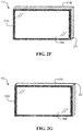
- FIGS. 2F and 2G illustrate examples of an information handling system in a “360” degree mode, according to one or more embodiments
- FIGS. 2H and 2I illustrate examples of an information handling system in multiple presentation modes, according to one or more embodiments
- FIGS. 2J and 2K illustrate examples of an information handling system in multiple other presentation modes, according to one or more embodiments
- FIG. 2L illustrates an example of an information handling system that includes a housing and a lid, according to one or more embodiments
- FIGS. 3A and 3B illustrates examples of an information handling system that includes multiple battery systems, according to one or more embodiments
- FIG. 4 illustrates a battery system, according to one or more embodiments
- FIG. 5 illustrates an example embedded controller, according to one or more embodiments
- FIG. 6A illustrates an example of a user interacting with an information handling system, according to one or more embodiments
- FIG. 6B illustrates an example of holding an information handling system, according to one or more embodiments.
- FIGS. 7A and 7B illustrate an example of a method of operating battery systems, according to one or more embodiments.
- a reference numeral refers to a class or type of entity, and any letter following such reference numeral refers to a specific instance of a particular entity of that class or type.
- a hypothetical entity referenced by ‘12A’ may refer to a particular instance of a particular class/type, and the reference ‘12’ may refer to a collection of instances belonging to that particular class/type or any one instance of that class/type in general.
- an information handling system may include one or more elements that generate heat.
- one or more thermal specifications may be utilized in determining a temperature that is appropriate for a surface of information handling system that may contact a user.
- a maximum temperature for a glass portion of the information handling system that may contact the user may be twenty-two degrees Celsius (22° C.) above an ambient temperature.
- an ambient temperature may be or may be around twenty-eight degrees Celsius (28° C.).
- a maximum temperature for a metallic portion of the information handling system that may contact the user may be eleven degrees Celsius (11° C.) above an ambient temperature.
- an ambient temperature may be or may be around twenty-eight degrees Celsius (28° C.).
- a maximum temperature for a plastic portion of the information handling system that may contact the user may be twelve degrees Celsius (12° C.) above an ambient temperature.
- an ambient temperature may be or may be around twenty-eight degrees Celsius (28° C.).
- a user may rest a portion of his or her body against an information handling system when utilizing the information handling system.
- the user may rest one or more of a hand, a palm of the hand, and one or more fingers of the hand against the information handling system while interacting with the information handling system.
- the user may rest a forearm against the information handling system while interacting with the information handling system.
- an information handling system may include one or more displays. For example, the user may contact a portion of his or her body with the one or more displays of the information handling system.
- a surface of a display of the information handling system may include one or more of glass and plastic, and if one or more temperatures of the surface, contacting the user, are not below a threshold temperature, a user experience may be less than optimal or may be a poor user experience.
- controlling one or more temperatures of one or more portions of an information handling system that may contact a user of the information handling system may provide one or more advantages.
- the one or more advantages may include one or more of a good user experience, faster processing of information, longer battery system life, and better utilization of multiple displays, among others.
- distributing one or more of power and processing through the information handling system may include determining how the information handling system is being utilized. For example, determining how the information handling system is being utilized may include determining one or more applications (e.g., one or more of a drawing application, an image processing application, a word processing application, a computer-aided design (CAD) application, a mathematics application (e.g., Mathematica, MathCAD, etc.), a video processing application, and a sound processing application, among others) that are executing and/or being utilized by the user. In one instance, the information handling system may determine if an on-screen keyboard is being utilized by the user.
- applications e.g., one or more of a drawing application, an image processing application, a word processing application, a computer-aided design (CAD) application, a mathematics application (e.g., Mathematica, MathCAD, etc.), a video processing application, and a sound processing application, among others.
- the information handling system may determine if an on-screen keyboard is
- the information handling system may determine if an external mouse and/or keyboard is communicatively coupled to the information handling system. In a third instance, the information handling system may determine an orientation of the information handling system and/or one or more orientation of one or more displays of the information handling system. In another instance, the information handling system may determine if a stylus is utilized by the user. In one or more embodiments, the information handling system may determine an operating mode of the information handling system.
- an operating mode of the information handling system may include a laptop mode (e.g., one display that outputs information from an application and another display that receives user input, such as a keyboard), a dual screen on a dock (e.g., multiple displays coupled to a docking station and/or at an angle), dual display on a surface (e.g., multiple displays are “face up” on a table/desk/etc.).
- a laptop mode e.g., one display that outputs information from an application and another display that receives user input, such as a keyboard
- a dual screen on a dock e.g., multiple displays coupled to a docking station and/or at an angle
- dual display on a surface e.g., multiple displays are “face up” on a table/desk/etc.
- the information handling system may determine one or more modes, methods, and/or processes in controlling and/or handling thermal aspects, processing distribution, battery system charging, battery system discharging, and/or power distribution based at least on various determinations. In one or more embodiments, the information handling system may adjust, control, and/or handle one or more thermal aspects of the information handling system based at least on a portion of a user in contact with the information handling system. In one example, processing may be migrated from a first portion of the information handling system to a second portion, different from the first portion, of the information handling system.
- processing may be migrated from a first processor associated with a first display of the multiple displays to a second processor associated with a second display of the multiple displays.
- processing may be boosted.
- processing may be migrated back to the first portion of the information handling system.
- processing may be augmented by the first portion of the information handling system.
- an information handling system may include multiple battery systems.
- battery system charging may be migrated from a first portion of the information handling system to another portion of the information handling system.
- one or more of the multiple battery systems may generate heat.
- one or more of the multiple battery systems may generate heat while being charged.
- one or more of the multiple battery systems may generate heat while being discharged.
- utilizing multiple battery systems may create one or more scenarios where one or more thermal specifications may initially conflicted with but may not conflicted with one or more absolute thermal thresholds. For example, one or more thermal deltas between two portions of an information handling system may not be conflicted with.
- an information handling system may receive power from an external power source.
- the information handling system may receive power from an external power supply.
- performance of the information handling system may decrease from an increased thermal load of a battery system, as circuitry of the information handling system may reduce power to other one or more components of the information handling system.
- reducing power to the one or more components of the information handling system may reduce one or more processing capabilities of the information handling system.
- one or more of a processor, a graphics processing unit, and a storage device, among others, of the information handling system may utilize a slower clock speed to reduce power consumption.
- heat may be associated with charging and/or discharging a battery system.
- charging a battery system may be ninety percent (90%) efficient.
- 15 W fifteen watts
- 1.5 W 1.5 watts
- multiple battery systems of an information handling system may be distributed to multiple portions of the information handling system. For example, utilizing the multiple battery systems at the multiple portions of the information handling system may mitigate infringing one or more thermal specifications.
- charging or discharging a first battery system of the multiple battery systems at a first portion of the information handling system may be switched to charging or discharging a second battery system of the multiple battery systems at a second portion of the information handling system if a temperature difference associated with the first battery system and the second battery system is above a threshold.
- heat may shorten a lifespan of a battery system.
- heat may degrade one or more chemistries and/or one or more structures of a battery system.
- reducing heat associated with a battery system may aid in abridging a shortened lifespan of a battery system associated with heat.
- the battery system may not be utilized until a temperature associated with the battery system is below the maximum temperature threshold or is below the maximum temperature threshold by a number of degrees.
- the battery system may not be utilized until a temperature associated with the battery system is below the maximum temperature threshold or is below the maximum temperature for an amount of time.
- An information handling system (IHS) 110 may include a hardware resource or an aggregate of hardware resources operable to compute, classify, process, transmit, receive, retrieve, originate, switch, store, display, manifest, detect, record, reproduce, handle, and/or utilize various forms of information, intelligence, or data for business, scientific, control, entertainment, or other purposes, according to one or more embodiments.
- IHS 110 may be a personal computer, a desktop computer system, a laptop computer system, a server computer system, a mobile device, a tablet computing device, a personal digital assistant (PDA), a consumer electronic device, an electronic music player, an electronic camera, an electronic video player, a wireless access point, a network storage device, or another suitable device and may vary in size, shape, performance, functionality, and price.
- a portable IHS 110 may include or have a form factor of that of or similar to one or more of a laptop, a notebook, a telephone, a tablet, and a PDA, among others.
- a portable IHS 110 may be readily carried and/or transported by a user (e.g., a person).
- components of IHS 110 may include one or more storage devices, one or more communications ports for communicating with external devices as well as various input and output (I/O) devices, such as a keyboard, a mouse, and a video display, among others.
- IHS 110 may include one or more buses operable to transmit communication between or among two or more hardware components.
- a bus of IHS 110 may include one or more of a memory bus, a peripheral bus, and a local bus, among others.
- a bus of IHS 110 may include one or more of a Micro Channel Architecture (MCA) bus, an Industry Standard Architecture (ISA) bus, an Enhanced ISA (EISA) bus, a Peripheral Component Interconnect (PCI) bus, HyperTransport (HT) bus, an inter-integrated circuit (I 2 C) bus, a serial peripheral interface (SPI) bus, a low pin count (LPC) bus, an enhanced serial peripheral interface (eSPI) bus, a universal serial bus (USB), a system management bus (SMBus), and a Video Electronics Standards Association (VESA) local bus, among others.
- MCA Micro Channel Architecture
- ISA Industry Standard Architecture
- EISA Enhanced ISA
- PCI Peripheral Component Interconnect
- HT HyperTransport
- I 2 C inter-integrated circuit
- SPI serial peripheral interface
- LPC low pin count
- eSPI enhanced serial peripheral interface
- USB universal serial bus
- SMB system management bus
- VESA Video Electronics Standards Association
- IHS 110 may include firmware that controls and/or communicates with one or more hard drives, network circuitry, one or more memory devices, one or more I/O devices, and/or one or more other peripheral devices.
- firmware may include software embedded in an IHS component utilized to perform tasks.
- firmware may be stored in non-volatile memory, such as storage that does not lose stored data upon loss of power.
- firmware associated with an IHS component may be stored in non-volatile memory that is accessible to one or more IHS components.
- firmware associated with an IHS component may be stored in non-volatile memory that may be dedicated to and includes part of that component.
- an embedded controller may include firmware that may be stored via non-volatile memory that may be dedicated to and includes part of the embedded controller.
- IHS 110 may include a processor 120 , a volatile memory medium 150 , non-volatile memory media 160 and 170 , an I/O subsystem 175 , a network interface 180 , a display 185 A, a graphics processing unit (GPU) 190 , and an embedded controller (EC) 195 .
- GPU 190 may be or include a discrete GPU (dGPU).
- volatile memory medium 150 , non-volatile memory media 160 and 170 , I/O subsystem 175 , network interface 180 , display 185 A, GPU 190 , and EC 195 may be communicatively coupled to processor 120 . As shown FIG.
- IHS 110 may include processor 120 , volatile memory medium 150 , non-volatile memory media 160 and 170 , I/O subsystem 175 , network interface 180 , displays 185 A and 185 B, GPU 190 , and EC 195 .
- volatile memory medium 150 , non-volatile memory media 160 and 170 , I/O subsystem 175 , network interface 180 , displays 185 A and 185 B, and GPU 190 may be communicatively coupled to processor 120 .
- sensors 196 A- 196 C may be coupled to EC 195 .
- a sensor 196 may sample physical phenomena and provide data associated with the physical phenomena to EC 195 .
- sensor 196 may determine a temperature.
- sensor 196 may provide data associated with the temperature to EC 195 .
- sensor 196 may determine an acceleration.
- sensor 196 may provide data associated with the acceleration to EC 195 .
- sensor 196 may determine a magnetic field.
- sensors 196 may provide data associated with the magnetic field to EC 195 .
- sensors 196 A- 196 C may be distributed in a housing of IHS 110 .
- sensor 196 may provide data to EC 195 via a sensor hub, according to one or more embodiments.
- one or more of volatile memory medium 150 , non-volatile memory media 160 and 170 , I/O subsystem 175 , network interface 180 , GPU 190 , and EC 195 may be communicatively coupled to processor 120 via one or more buses, one or more switches, and/or one or more root complexes, among others.
- one or more of volatile memory medium 150 , non-volatile memory media 160 and 170 , I/O subsystem 175 , and network interface 180 may be communicatively coupled to processor 120 via one or more PCI-Express (PCIe) root complexes.
- PCIe PCI-Express
- one or more of an I/O subsystem 175 and a network interface 180 may be communicatively coupled to processor 120 via one or more PCIe switches.
- the term “memory medium” may mean a “storage device”, a “memory”, a “memory device”, a “tangible computer readable storage medium”, and/or a “computer-readable medium”.
- computer-readable media may include, without limitation, storage media such as a direct access storage device (e.g., a hard disk drive, a floppy disk, etc.), a sequential access storage device (e.g., a tape disk drive), a compact disk (CD), a CD-ROM, a digital versatile disc (DVD), a random access memory (RAM), a read-only memory (ROM), a one-time programmable (OTP) memory, an electrically erasable programmable read-only memory (EEPROM), and/or a flash memory, a solid state drive (SSD), or any combination of the foregoing, among others.
- direct access storage device e.g., a hard disk drive, a floppy disk, etc.
- sequential access storage device e.g.
- one or more protocols may be utilized in transferring data to and/or from a memory medium.
- the one or more protocols may include one or more of small computer system interface (SCSI), Serial Attached SCSI (SAS) or another transport that operates with the SCSI protocol, advanced technology attachment (ATA), serial ATA (SATA), a USB interface, an Institute of Electrical and Electronics Engineers (IEEE) 1394 interface, a Thunderbolt interface, an advanced technology attachment packet interface (ATAPI), serial storage architecture (SSA), integrated drive electronics (IDE), or any combination thereof, among others.
- SCSI small computer system interface
- SAS Serial Attached SCSI
- ATA advanced technology attachment
- SATA serial ATA
- USB interface an Institute of Electrical and Electronics Engineers 1394 interface
- Thunderbolt interface an advanced technology attachment packet interface
- ATAPI advanced technology attachment packet interface
- SSA serial storage architecture
- IDE integrated drive electronics
- Volatile memory medium 150 may include volatile storage such as, for example, RAM, DRAM (dynamic RAM), EDO RAM (extended data out RAM), SRAM (static RAM), etc.
- One or more of non-volatile memory media 160 and 170 may include nonvolatile storage such as, for example, a read only memory (ROM), a programmable ROM (PROM), an erasable PROM (EPROM), an electrically erasable PROM, NVRAM (non-volatile RAM), ferroelectric RAM (FRAM), a magnetic medium (e.g., a hard drive, a floppy disk, a magnetic tape, etc.), optical storage (e.g., a CD, a DVD, a BLU-RAY disc, etc.), flash memory, a SSD, etc.
- a memory medium can include one or more volatile storages and/or one or more nonvolatile storages.
- network interface 180 may be utilized in communicating with one or more networks and/or one or more other information handling systems.
- network interface 180 may enable IHS 110 to communicate via a network utilizing a suitable transmission protocol and/or standard.
- network interface 180 may be coupled to a wired network.
- network interface 180 may be coupled to an optical network.
- network interface 180 may be coupled to a wireless network.
- network interface 180 may be communicatively coupled via a network to a network storage resource.
- the network may be implemented as, or may be a part of, a storage area network (SAN), personal area network (PAN), local area network (LAN), a metropolitan area network (MAN), a wide area network (WAN), a wireless local area network (WLAN), a virtual private network (VPN), an intranet, an Internet or another appropriate architecture or system that facilitates the communication of signals, data and/or messages (generally referred to as data).
- SAN storage area network
- PAN personal area network
- LAN local area network
- MAN metropolitan area network
- WAN wide area network
- WLAN wireless local area network
- VPN virtual private network
- intranet an Internet or another appropriate architecture or system that facilitates the communication of signals, data and/or messages (generally referred to as data).
- the network may transmit data utilizing a desired storage and/or communication protocol, including one or more of Fibre Channel, Frame Relay, Asynchronous Transfer Mode (ATM), Internet protocol (IP), other packet-based protocol, Internet SCSI (iSCSI), or any combination thereof, among others.
- a desired storage and/or communication protocol including one or more of Fibre Channel, Frame Relay, Asynchronous Transfer Mode (ATM), Internet protocol (IP), other packet-based protocol, Internet SCSI (iSCSI), or any combination thereof, among others.
- processor 120 may execute processor instructions in implementing one or more systems, flowcharts, methods, and/or processes described herein. In one example, processor 120 may execute processor instructions from one or more of memory media 150 - 170 in implementing one or more systems, flowcharts, methods, and/or processes described herein. In another example, processor 120 may execute processor instructions via network interface 180 in implementing one or more systems, flowcharts, methods, and/or processes described herein.
- processor 120 may include one or more of a system, a device, and an apparatus operable to interpret and/or execute program instructions and/or process data, among others, and may include one or more of a microprocessor, a microcontroller, a digital signal processor (DSP), an application specific integrated circuit (ASIC), and another digital or analog circuitry configured to interpret and/or execute program instructions and/or process data, among others.
- processor 120 may interpret and/or execute program instructions and/or process data stored locally (e.g., via memory media 150 - 170 and/or another component of IHS 110 ).
- processor 120 may interpret and/or execute program instructions and/or process data stored remotely (e.g., via a network storage resource).
- I/O subsystem 175 may represent a variety of communication interfaces, graphics interfaces, video interfaces, user input interfaces, and/or peripheral interfaces, among others.
- I/O subsystem 175 may include one or more of a touch panel and a display adapter, among others.
- a touch panel may include circuitry that enables touch functionality in conjunction with a display that is driven by a display adapter.
- non-volatile memory medium 160 may include an operating system (OS) 162 , and applications (APPs) 164 - 168 .
- OS 162 and APPs 164 - 168 may include processor instructions executable by processor 120 .
- processor 120 may execute processor instructions of one or more of OS 162 and APPs 164 - 168 via non-volatile memory medium 160 .
- one or more portions of the processor instructions of the one or more of OS 162 and APPs 164 - 168 may be transferred to volatile memory medium 150 , and processor 120 may execute the one or more portions of the processor instructions of the one or more of OS 162 and APPs 164 - 168 via volatile memory medium 150 .
- non-volatile memory medium 170 may include information handling system firmware (IHSFW) 172 .
- IHSFW 172 may include processor instructions executable by processor 120 .
- IHSFW 172 may include one or more structures and/or one or more functionalities of one or more of a basic input/output system (BIOS), an Extensible Firmware Interface (EFI), a Unified Extensible Firmware Interface (UEFI), and an Advanced Configuration and Power Interface (ACPI), among others.
- BIOS basic input/output system
- EFI Extensible Firmware Interface
- UEFI Unified Extensible Firmware Interface
- ACPI Advanced Configuration and Power Interface
- processor 120 may execute processor instructions of IHSFW 172 via non-volatile memory medium 170 .
- one or more portions of the processor instructions of IHSFW 172 may be transferred to volatile memory medium 150 , and processor 120 may execute the one or more portions of the processor instructions of IHSFW 172 via volatile memory medium 150 .
- processor 120 and one or more components of IHS 110 may be included in a system-on-chip (SoC).
- SoC may include processor 120 and a platform controller hub (not specifically illustrated).
- IHS 110 may include housings 210 A and 210 B.
- housings 210 A and 210 B may be joined via a hinge mechanism 215 .
- housing 210 A may include one or more of display 185 A, an orientation sensor 220 A, a directional sensor 225 A, a camera 230 A, and a gyroscopic sensor 235 B.
- orientation sensor 220 A, directional sensor 225 A, camera 230 A, and gyroscopic sensor 235 A may be communicatively coupled to processor 120 and/or EC 195 , according to one or more embodiments.
- housing 210 B may include one or more of display 185 B, an orientation sensor 220 B, a directional sensor 225 B, a camera 230 B, and a gyroscopic sensor 235 B.
- orientation sensor 220 B, directional sensor 225 B, camera 230 B, and gyroscopic sensor 235 B may be communicatively coupled to processor 120 , according to one or more embodiments.
- one or more of housings 210 A and 210 B may operate to provide information to a user of IHS 110 .
- display 185 A may provide information in association with display 185 B.
- display 185 A may provide information that is not associated with display 185 B.
- one of display displays 285 A and 285 B may provide information while the other display may be blank, as needed and/or desired.
- displays 285 A and 285 B may represent combined input/output devices for IHS 110 .
- displays 285 A and 285 B may be or include respective touch-screen displays, that operate to display and/or receive information associated with respective housings 210 A and 210 B.
- each of one or more of displays 285 A and 285 B may display a keyboard interface and receive touch-based keyboard inputs.
- each of one or more of displays 285 A and 285 B may include a gesture-enabled display device that is configured to detect the motion of a touch over a surface the display.
- each of one or more of displays 285 A and 285 B may include a multi-touch-enabled display device that is configured to detect two or more simultaneous touch contacts on the surface of the display.
- each of one or more of displays 285 A and 285 B may include a hover-sensitive display device that is configured to detect a presence of a touch device and/or a portion of a user hovering in proximity over the surface of the display.
- processor 120 may receive information from one or more of orientation sensors 220 A and 220 B, directional sensors 225 A and 225 B, cameras 230 A and 230 B, and gyroscopic sensors 235 A and 235 B, among others.
- one or more of orientation sensors 220 A and 220 B, directional sensors 225 A and 225 B, and gyroscopic sensors 235 A and 235 B, among others may be utilized in determining an orientation in space of respective housings 210 A and 210 B, based at least on a three-dimensional coordinate system.
- orientation sensor 220 A, directional sensor 225 A, and gyroscopic sensor 235 A may be utilized in determining that housing 210 A is oriented horizontally, vertically with a bottom parallel to the ground, vertically with a side parallel to the ground, and/or in an intermediate orientation, among others.
- orientation sensor 220 B, directional sensor 225 B, and gyroscopic sensor 235 B, among others may be utilized in determining that housing 210 B is oriented horizontally, vertically with a bottom parallel to the ground, vertically with a side parallel to the ground, and/or in an intermediate orientation, among others.
- one or more of directional sensors 225 A and 225 B may be configured to determine an orientation with respect to magnetic north of a major axis to one or more of housings 210 A and 210 B.
- direction sensor 225 A may be utilized in determining a compass bearing of a line oriented along a side of the housing.
- one or more of directional sensors 225 A and 225 B may include one or more magnetometers and/or one or more accelerometers, among others.
- one or more of cameras 230 A and 230 B may be configured to receive photonic input.
- one or more of cameras 230 A and 230 B may be utilized to receive light input and provide one or more of still images and/or one or more videos.
- one or more of cameras 230 A and 230 B may be utilized in determining motion and/or presence of a pointing device and/or a user in proximity to one or more of housings 210 A and 210 B, among others.
- one or more of cameras 230 A and 230 B may be utilized in determining a direction of a glance of a user of IHS 110 .
- camera 230 A may be utilized in determining if a user is looking at the top-left corner of housing 210 A and/or in determining if the user is looking at a bottom-right corner of housing 210 A.
- one or more of cameras 230 A and 230 B may be utilized in following a glance of the user, as the glance moves across one or more of housing 210 A and 210 B.
- one or more of gyroscopic sensors 235 A and 235 B may be utilized in determining a rotational motion of respective housings 210 A and 210 B and/or in determining one or more rates of rotational motion.
- hinge mechanism 215 may coupled housings 210 A and 210 B.
- hinge mechanism 215 may include a hinge that joins an edge of housing 210 A to an edge of housing 210 B.
- hinge mechanism 215 may operate to permit housing 210 A to swing to any angle between 0 and 360 degrees of arc with respect to housing 210 B.
- IHS 110 is in an orientation where housing 210 A is swung to a 180 degree angle with respect to housing 210 B.
- FIG. 2B an example of an information handling system that includes multiple displays, where an orientation of a first housing is swung to a 0 degree angle with respect to a second housing, is illustrated, according to one or more embodiments.
- IHS 110 is in a state that is normally associated as a “closed” state.
- displays 185 A and 185 B may be facing each other in the “closed” state.
- IHS 110 may be in a landscape orientation.
- IHS 110 may be in a portrait orientation.
- the portrait orientation and/or the landscape orientation may be with respect to the ground.
- the portrait orientation and/or the landscape orientation may be with respect to a user.
- housing 210 A may be at an angle ⁇ to housing 210 B.
- ⁇ may be greater than 0 degrees and less than 180 degrees.
- IHS 110 may be in a “360” degree mode.
- the 360 degree mode may be utilized in a dual presentation.
- the 360 degree mode may be utilized when a user utilizes one display. For example, one of displays 185 A and 185 B may be utilized, while the other display faces away from the user. For instance, the other display may be laying on a surface, a palm of a user, or a lap of the user, among others.
- housing 210 A may be at an angle ⁇ to housing 210 B.
- ⁇ may be greater than 180 degrees and less than 360 degrees.
- IHS 110 may be in a single presentation mode.
- IHS 110 may be in a dual presentation mode. For instance, IHS 110 may be “tented”.
- IHS 110 may be in portrait modes.
- IHS 110 may be in portrait mode in FIG. 2J
- IHS 110 may be in a landscape mode in FIG. 2E .
- IHS 110 may be in portrait mode in FIG. 2K
- IHS 110 may be in a landscape mode in FIG. 2F .
- IHS 110 may include a housing 210 .
- IHS 110 may include a lid 212 .
- lid 212 may be a housing of IHS 110 .
- lid 212 may include display 185 A.
- housing 210 A of IHS 110 may include battery systems 310 A- 310 C.
- housing 210 B of IHS 110 may include battery systems 310 D- 310 F.
- housing 210 of IHS 110 may include battery systems 310 A- 310 C.
- portions 320 A- 320 C of IHS 110 and/or housing 210 may include respective battery systems 310 A- 310 C.
- portions of housing 210 A may include respective battery systems 310 A- 310 C
- portions of housing 210 B may include respective battery systems 310 D- 310 F, according to one or more embodiments.
- battery system 310 may include circuitry 420 and cells 430 A- 430 C (e.g., electrochemical cells, voltaic cells, etc.).
- battery system 310 may provide power to IHS 110 .
- battery system 310 may provide power to one or more components of IHS 110 .
- battery system 310 may receive power from IHS 110 .
- battery system 310 may communicate with IHS 110 .
- battery system 310 may include a sensor 440 .
- sensor 440 may sense and/or determine one or more temperatures.
- sensor 440 may be coupled to circuitry 420 .
- sensor 440 may be or include sensor 196 .
- circuitry 420 may regulate and/or monitor charging and/or discharging of battery system 310 .
- circuitry 420 may regulate charging and/or discharging of one or more of cells 430 A- 430 C.
- circuitry 420 may monitor charging and/or discharging.
- circuitry 420 may include a processor that may store information associated with charging and/or discharging of battery system 310 and/or may provide the information associated with charging and/or discharging of battery system 310 . For instance, the information associated with charging and/or discharging of battery system 310 may be provided, by circuitry 420 , to one or more of processor 120 and EC 195 , among others.
- circuitry 420 may include a processor that may store information associated with one or more temperatures of battery system 310 and/or may provide the information associated with the one or more temperatures of battery system 310 .
- the information associated with the one or more temperatures of battery system 310 may be provided, by circuitry 420 , to one or more of processor 120 and EC 195 , among others.
- EC 195 may include a processor 520 , a volatile memory medium 550 , a non-volatile memory medium 570 , and an interface 580 .
- non-volatile memory medium 574 may include an EC firmware (FW) 574 , which may include an OS 562 and APPs 564 - 568 , and may include EC data 577 .
- OS 562 may be or include a real-time operating system (RTOS).
- RTOS real-time operating system
- interface 580 may include circuitry that enables communicatively coupling to one or more devices.
- interface 580 may include circuitry that enables communicatively coupling to one or more buses.
- interface 580 may include circuitry that enables one or more interrupt signals to be received.
- interface 580 may include general purpose input/output (GPIO) circuitry, and the GPIO circuitry may enable one or more interrupt signals to be received and/or provided via at least one interrupt line.
- interface 580 may include GPIO circuitry that may enable EC 195 to provide and/or receive signals associated with other circuitry.
- interface 580 may include circuitry that enables communicatively coupling to one or more networks.
- interface 580 may include circuitry that enables communicatively coupling to network interface 180 .
- interface 580 may include a network interface.
- one or more of OS 562 and APPs 564 - 568 may include processor instructions executable by processor 520 .
- processor 520 may execute processor instructions of one or more of OS 562 and APPs 564 - 568 via non-volatile memory medium 570 .
- one or more portions of the processor instructions of the one or more of OS 562 and APPs 564 - 568 may be transferred to volatile memory medium 550 , and processor 520 may execute the one or more portions of the processor instructions of the one or more of OS 562 and APPs 564 - 568 via volatile memory medium 550 .
- processor 520 may utilize EC data 577 .
- processor 520 may utilize EC data 577 via non-volatile memory medium 570 .
- processor 520 may utilize EC data 577 via volatile memory medium 550 .
- processor 520 may execute processor instructions in implementing one or more systems, flowcharts, methods, and/or processes described herein.
- processor 520 may execute processor instructions from one or more of memory media 550 and 570 in implementing one or more systems, flowcharts, methods, and/or processes described herein.
- a user 610 may interact with IHS 110 .
- one or more portions of user 610 may be in contact with IHS 110 .
- a forearm 620 A of user 610 may be in contact with IHS 110 .
- a forearm 620 B of user 610 may not be in contact with IHS 110 .
- forearm 620 A of user 610 may be contact with one or more of housing 210 A and display 185 A.
- IHS 110 may determine that one or more portions of user 610 may be in contact with IHS 110 .
- one or more touch-sensitive elements of IHS 110 may be utilized in determining if one or more portions of user 610 is in contact with IHS 110 .
- one or more proximity-sensing elements of IHS 110 may be utilized in determining if one or more portions of user 610 is in contact with IHS 110 .
- IHS 110 may be held by at least fingers 640 of a user. As illustrated, fingers 640 may contact display 185 A. Although not specifically illustrated, a palm of the user may contact display 185 B or housing 210 . For example, the palm of the user may contact display 185 B or housing 210 to hold IHS 110 . In one instance, IHS 110 may include displays 185 A and 185 B, and the palm of the user may contact display 185 B to hold IHS 110 . In another instance, IHS 110 may be a tablet computing device, and the palm of the user may contact housing 210 to hold IHS 110 . As shown, battery systems 310 A- 310 C may be distributed within housing 210 . For example, battery systems 310 A- 310 C may be located behind display 185 A.
- FIGS. 7A and 7B an example of a method of operating battery systems is illustrated, according to one or more embodiments.
- a first battery system of multiple battery systems associated with a first portion of multiple portions of an information handling system, is being charged. If the first battery system is not being charged, a temperature associated with a second battery system, of the multiple battery systems of a second portion of the multiple portions of the information handling system, may be determined, at 712 .
- a temperature associated with a second battery system of the multiple battery systems of a second portion of the multiple portions of the information handling system, may be determined, at 712 .
- the first battery may be battery system 310 B.
- the second battery system may be battery system 310 F, associated with housing 210 B (e.g., a second portion of IHS 110 ).
- the second battery system may be battery system 310 C, associated with portion 320 C.
- the second portion of the information handling system may be associated with a temperature that is less than a temperature associated with the first portion of the information handling system. For example, it may be determined that second portion of the information handling system is associated with a temperature that is less than a temperature associated with the first portion of the information handling system.
- the second battery may be discharged, at 720 .
- discharging the second battery system may include the second battery system providing power to one or more components of the information handling system.
- the first battery system may be discharged, at 725 .
- discharging the first system battery may include the first battery system providing power to one or more components of the information handling system.
- a first temperature measurement associated with the first battery system may be determined, at 726 .
- a second temperature measurement associated with the first battery system may be determined.
- the second temperature measurement associated with the first battery system may be determined after a period of time transpires.
- a temperature change, from the first temperature measurement associated with the first battery system and the second temperature measurement associated with the first battery system may be determined.
- determining a temperature change, from the first temperature measurement associated with the first battery system and the second temperature measurement associated with the first battery system may include comparing the first temperature measurement associated with the first battery system and the second temperature measurement associated with the first battery system.
- comparing the first temperature measurement associated with the first battery system and the second temperature measurement associated with the first battery system may include subtracting the first temperature measurement associated with the first battery system from the second temperature measurement associated with the first battery system.
- subtracting the first temperature measurement associated with the first battery system from the second temperature measurement associated with the first battery system produces a non-zero and positive number
- the temperature of the first battery system may be increasing.
- subtracting the first temperature measurement associated with the first battery system from the second temperature measurement associated with the first battery system produces a non-zero and negative number
- the temperature of the first battery system may be decreasing.
- sensor 196 A may determine the first temperature measurement associated with the first battery system and the second temperature measurement associated with the first battery system. In one example, sensor 196 A may be proximate to the first battery system. In a second example, sensor 196 A may be in contact with the first battery system. In a third example, the first battery system may include sensor 196 A. In fourth example, housing 210 A (e.g., a first portion of IHS 110 ) may include battery system 310 B (e.g., the firth battery system) and sensor 196 A. In another example, portion 320 B (e.g., a first portion of IHS 110 ) may include battery system 310 B (e.g., the firth battery system) and sensor 196 A.
- housing 210 A e.g., a first portion of IHS 110
- portion 320 B e.g., a first portion of IHS 110
- portion 320 B may include battery system 310 B (e.g., the firth battery system) and sensor
- the temperature change associated with the first battery system may be determined if the temperature change associated with the first battery system is increasing. If the temperature change associated with the first battery system is increasing, it may be determined if the temperature change is above a maximum threshold, at 735 . If the temperature change is not above the maximum threshold, the first battery system may be charged, at 775 . If the temperature change is above the maximum threshold, it may be determined if the second battery system is fully charged, at 740 . If the second battery system is not fully charged, the second battery system may be charged at 765 . If the second battery system is fully charged, a rate of charge to the first battery system may be reduced, at 745 . At 750 , the first battery system may be charged at a reduced rate.
- a temperature change associated with the first battery system is not increasing, it may be determined if temperature change associated with the first battery system is decreasing, at 755 . If temperature change associated with the first battery system is not decreasing, the method may proceed to 710 , according to one or more embodiments. If temperature change associated with the first battery system is decreasing, it may be determined if the temperature change associated with the first battery system is above a minimum threshold, at 760 . If the temperature change associated with the first battery system is not above the minimum threshold, the second battery system may be charged, at 765 .
- determining if the temperature change associated with the first battery system is above the minimum threshold may provide a shield against and/or provide mitigation from frequent shifting between charging the first battery system and charging the second battery system.
- one or more of the method and/or process elements and/or one or more portions of a method and/or processor elements may be performed in varying orders, may be repeated, or may be omitted.
- additional, supplementary, and/or duplicated method and/or process elements may be implemented, instantiated, and/or performed as desired, according to one or more embodiments.
- one or more of system elements may be omitted and/or additional system elements may be added as desired, according to one or more embodiments.
- a memory medium may be and/or may include an article of manufacture.
- the article of manufacture may include and/or may be a software product and/or a program product.
- the memory medium may be coded and/or encoded with processor-executable instructions in accordance with one or more flowcharts, systems, methods, and/or processes described herein to produce the article of manufacture.
Abstract
Description
Claims (20)
Priority Applications (1)
| Application Number | Priority Date | Filing Date | Title |
|---|---|---|---|
| US16/036,555 US10666078B2 (en) | 2018-07-16 | 2018-07-16 | System and method of managing battery systems |
Applications Claiming Priority (1)
| Application Number | Priority Date | Filing Date | Title |
|---|---|---|---|
| US16/036,555 US10666078B2 (en) | 2018-07-16 | 2018-07-16 | System and method of managing battery systems |
Publications (2)
| Publication Number | Publication Date |
|---|---|
| US20200021115A1 US20200021115A1 (en) | 2020-01-16 |
| US10666078B2 true US10666078B2 (en) | 2020-05-26 |
Family
ID=69138499
Family Applications (1)
| Application Number | Title | Priority Date | Filing Date |
|---|---|---|---|
| US16/036,555 Active 2038-11-22 US10666078B2 (en) | 2018-07-16 | 2018-07-16 | System and method of managing battery systems |
Country Status (1)
| Country | Link |
|---|---|
| US (1) | US10666078B2 (en) |
Families Citing this family (3)
| Publication number | Priority date | Publication date | Assignee | Title |
|---|---|---|---|---|
| US11817710B2 (en) * | 2018-08-07 | 2023-11-14 | Kyocera Corporation | Control apparatus and control method for controlling charge and discharge of storage battery apparatuses |
| JP7010191B2 (en) * | 2018-10-23 | 2022-02-10 | トヨタ自動車株式会社 | Secondary battery system and charge control method for secondary batteries |
| US11016544B2 (en) * | 2019-07-02 | 2021-05-25 | Microsoft Technology Licensing, Llc | System and method for adaptive thermal management of battery packs |
Citations (5)
| Publication number | Priority date | Publication date | Assignee | Title |
|---|---|---|---|---|
| US20020175658A1 (en) * | 2001-05-25 | 2002-11-28 | Watts Fred S. | Method and apparatus for charging batteries |
| US20040257089A1 (en) * | 2003-06-20 | 2004-12-23 | Koji Aridome | Temperature abnormality detecting apparatus and method for secondary battery |
| US20120176080A1 (en) * | 2010-07-30 | 2012-07-12 | Sanyo Electric Co., Ltd. | Secondary battery storage system rack |
| US9606664B2 (en) | 2013-11-13 | 2017-03-28 | Dell Products, Lp | Dynamic hover sensitivity and gesture adaptation in a dual display system |
| US20180252774A1 (en) * | 2017-03-03 | 2018-09-06 | Gentherm Incorporated | Dual voltage battery system for a vehicle |
-
2018
- 2018-07-16 US US16/036,555 patent/US10666078B2/en active Active
Patent Citations (5)
| Publication number | Priority date | Publication date | Assignee | Title |
|---|---|---|---|---|
| US20020175658A1 (en) * | 2001-05-25 | 2002-11-28 | Watts Fred S. | Method and apparatus for charging batteries |
| US20040257089A1 (en) * | 2003-06-20 | 2004-12-23 | Koji Aridome | Temperature abnormality detecting apparatus and method for secondary battery |
| US20120176080A1 (en) * | 2010-07-30 | 2012-07-12 | Sanyo Electric Co., Ltd. | Secondary battery storage system rack |
| US9606664B2 (en) | 2013-11-13 | 2017-03-28 | Dell Products, Lp | Dynamic hover sensitivity and gesture adaptation in a dual display system |
| US20180252774A1 (en) * | 2017-03-03 | 2018-09-06 | Gentherm Incorporated | Dual voltage battery system for a vehicle |
Also Published As
| Publication number | Publication date |
|---|---|
| US20200021115A1 (en) | 2020-01-16 |
Similar Documents
| Publication | Publication Date | Title |
|---|---|---|
| CN106462208B (en) | USB power delivery controller sharing | |
| US10712805B2 (en) | System and method of thermal management of information handling systems | |
| US10666078B2 (en) | System and method of managing battery systems | |
| EP3018554A1 (en) | Intergrated clock differential buffering | |
| EP4109281A1 (en) | Peer-to-peer link sharing for upstream communications from xpus to a host processor | |
| US11829216B2 (en) | System and method of enhancing performances of information handling systems by utilizing graphics processing units | |
| US20230072152A1 (en) | Management of workspaces across multiple clients | |
| US10305314B2 (en) | System and method of wirelessly charging devices | |
| US10852979B1 (en) | System and method of utilizing a non-volatile solid state storage device | |
| US10739840B2 (en) | System and method of utilizing operating context information | |
| US10482014B2 (en) | System and method of managing a memory medium | |
| US20230350471A1 (en) | Method of fan control in an information handling system using a pseudo temperature sensor | |
| US20190089817A1 (en) | System and Method of Utilizing Multiple Wireless Protocols | |
| US11269407B2 (en) | System and method of determining attributes of a workspace configuration based on eye gaze or head pose | |
| US10996727B2 (en) | System and method of managing power in information handling system | |
| US10571981B2 (en) | System and method of transferring energy in information handling system | |
| US11836522B2 (en) | System and method of managing temperatures of surfaces of information handling systems | |
| US10620692B2 (en) | System and method of operating one or more information handling systems | |
| US10621135B2 (en) | System and method of managing signals in information handling systems | |
| US11152811B2 (en) | System and method of operating an information handling system | |
| US11249540B2 (en) | System and method of configuring power consumption of a processor and a graphics processing unit | |
| US20150309557A1 (en) | Insertable housing for electronic device | |
| US10783226B2 (en) | System and method of utilizing a stylus | |
| US11294438B2 (en) | System and method of providing power from one portion of an information handling system to another portion of the information handling system | |
| US10948958B2 (en) | System and method of utilizing power supply units |
Legal Events
| Date | Code | Title | Description |
|---|---|---|---|
| AS | Assignment |
Owner name: DELL PRODUCTS L.P., TEXAS Free format text: ASSIGNMENT OF ASSIGNORS INTEREST;ASSIGNORS:FILES, JACE WILLIAM;MORRISON, JOHN TREVOR;PELISSIER, GERALD RENE;SIGNING DATES FROM 20180710 TO 20180711;REEL/FRAME:046362/0238 |
|
| FEPP | Fee payment procedure |
Free format text: ENTITY STATUS SET TO UNDISCOUNTED (ORIGINAL EVENT CODE: BIG.); ENTITY STATUS OF PATENT OWNER: LARGE ENTITY |
|
| AS | Assignment |
Owner name: THE BANK OF NEW YORK MELLON TRUST COMPANY, N.A., A Free format text: PATENT SECURITY AGREEMENT (NOTES);ASSIGNORS:DELL PRODUCTS L.P.;EMC CORPORATION;EMC IP HOLDING COMPANY LLC;REEL/FRAME:047648/0422 Effective date: 20180906 Owner name: CREDIT SUISSE AG, CAYMAN ISLANDS BRANCH, AS COLLAT Free format text: PATENT SECURITY AGREEMENT (CREDIT);ASSIGNORS:DELL PRODUCTS L.P.;EMC CORPORATION;EMC IP HOLDING COMPANY LLC;REEL/FRAME:047648/0346 Effective date: 20180906 Owner name: THE BANK OF NEW YORK MELLON TRUST COMPANY, N.A., AS COLLATERAL AGENT, TEXAS Free format text: PATENT SECURITY AGREEMENT (NOTES);ASSIGNORS:DELL PRODUCTS L.P.;EMC CORPORATION;EMC IP HOLDING COMPANY LLC;REEL/FRAME:047648/0422 Effective date: 20180906 Owner name: CREDIT SUISSE AG, CAYMAN ISLANDS BRANCH, AS COLLATERAL AGENT, NORTH CAROLINA Free format text: PATENT SECURITY AGREEMENT (CREDIT);ASSIGNORS:DELL PRODUCTS L.P.;EMC CORPORATION;EMC IP HOLDING COMPANY LLC;REEL/FRAME:047648/0346 Effective date: 20180906 |
|
| AS | Assignment |
Owner name: THE BANK OF NEW YORK MELLON TRUST COMPANY, N.A., T Free format text: SECURITY AGREEMENT;ASSIGNORS:CREDANT TECHNOLOGIES, INC.;DELL INTERNATIONAL L.L.C.;DELL MARKETING L.P.;AND OTHERS;REEL/FRAME:049452/0223 Effective date: 20190320 Owner name: THE BANK OF NEW YORK MELLON TRUST COMPANY, N.A., TEXAS Free format text: SECURITY AGREEMENT;ASSIGNORS:CREDANT TECHNOLOGIES, INC.;DELL INTERNATIONAL L.L.C.;DELL MARKETING L.P.;AND OTHERS;REEL/FRAME:049452/0223 Effective date: 20190320 |
|
| STPP | Information on status: patent application and granting procedure in general |
Free format text: NOTICE OF ALLOWANCE MAILED -- APPLICATION RECEIVED IN OFFICE OF PUBLICATIONS |
|
| AS | Assignment |
Owner name: THE BANK OF NEW YORK MELLON TRUST COMPANY, N.A., TEXAS Free format text: SECURITY AGREEMENT;ASSIGNORS:CREDANT TECHNOLOGIES INC.;DELL INTERNATIONAL L.L.C.;DELL MARKETING L.P.;AND OTHERS;REEL/FRAME:053546/0001 Effective date: 20200409 |
|
| STPP | Information on status: patent application and granting procedure in general |
Free format text: PUBLICATIONS -- ISSUE FEE PAYMENT VERIFIED |
|
| STCF | Information on status: patent grant |
Free format text: PATENTED CASE |
|
| AS | Assignment |
Owner name: EMC IP HOLDING COMPANY LLC, TEXAS Free format text: RELEASE OF SECURITY INTEREST AT REEL 047648 FRAME 0346;ASSIGNOR:CREDIT SUISSE AG, CAYMAN ISLANDS BRANCH;REEL/FRAME:058298/0510 Effective date: 20211101 Owner name: EMC CORPORATION, MASSACHUSETTS Free format text: RELEASE OF SECURITY INTEREST AT REEL 047648 FRAME 0346;ASSIGNOR:CREDIT SUISSE AG, CAYMAN ISLANDS BRANCH;REEL/FRAME:058298/0510 Effective date: 20211101 Owner name: DELL PRODUCTS L.P., TEXAS Free format text: RELEASE OF SECURITY INTEREST AT REEL 047648 FRAME 0346;ASSIGNOR:CREDIT SUISSE AG, CAYMAN ISLANDS BRANCH;REEL/FRAME:058298/0510 Effective date: 20211101 |
|
| AS | Assignment |
Owner name: EMC IP HOLDING COMPANY LLC, TEXAS Free format text: RELEASE OF SECURITY INTEREST IN PATENTS PREVIOUSLY RECORDED AT REEL/FRAME (047648/0422);ASSIGNOR:THE BANK OF NEW YORK MELLON TRUST COMPANY, N.A., AS NOTES COLLATERAL AGENT;REEL/FRAME:060160/0862 Effective date: 20220329 Owner name: EMC CORPORATION, MASSACHUSETTS Free format text: RELEASE OF SECURITY INTEREST IN PATENTS PREVIOUSLY RECORDED AT REEL/FRAME (047648/0422);ASSIGNOR:THE BANK OF NEW YORK MELLON TRUST COMPANY, N.A., AS NOTES COLLATERAL AGENT;REEL/FRAME:060160/0862 Effective date: 20220329 Owner name: DELL PRODUCTS L.P., TEXAS Free format text: RELEASE OF SECURITY INTEREST IN PATENTS PREVIOUSLY RECORDED AT REEL/FRAME (047648/0422);ASSIGNOR:THE BANK OF NEW YORK MELLON TRUST COMPANY, N.A., AS NOTES COLLATERAL AGENT;REEL/FRAME:060160/0862 Effective date: 20220329 |
|
| MAFP | Maintenance fee payment |
Free format text: PAYMENT OF MAINTENANCE FEE, 4TH YEAR, LARGE ENTITY (ORIGINAL EVENT CODE: M1551); ENTITY STATUS OF PATENT OWNER: LARGE ENTITY Year of fee payment: 4 |