EP1261081A2 - Method for assembling for flat cable connector and determining its connecting state - Google Patents
Method for assembling for flat cable connector and determining its connecting state Download PDFInfo
- Publication number
- EP1261081A2 EP1261081A2 EP02009389A EP02009389A EP1261081A2 EP 1261081 A2 EP1261081 A2 EP 1261081A2 EP 02009389 A EP02009389 A EP 02009389A EP 02009389 A EP02009389 A EP 02009389A EP 1261081 A2 EP1261081 A2 EP 1261081A2
- Authority
- EP
- European Patent Office
- Prior art keywords
- flat cable
- crimp pieces
- connecting terminal
- crimp
- conductor
- Prior art date
- Legal status (The legal status is an assumption and is not a legal conclusion. Google has not performed a legal analysis and makes no representation as to the accuracy of the status listed.)
- Granted
Links
- 238000000034 method Methods 0.000 title claims abstract description 50
- 239000004020 conductor Substances 0.000 claims abstract description 126
- 239000000758 substrate Substances 0.000 claims abstract description 42
- 239000011810 insulating material Substances 0.000 claims abstract description 20
- 230000000149 penetrating effect Effects 0.000 claims abstract description 19
- 238000005452 bending Methods 0.000 claims description 33
- 238000006073 displacement reaction Methods 0.000 claims description 27
- 230000003028 elevating effect Effects 0.000 claims description 12
- 230000007246 mechanism Effects 0.000 claims description 10
- 238000005192 partition Methods 0.000 claims description 9
- 230000008859 change Effects 0.000 description 10
- 230000002950 deficient Effects 0.000 description 6
- 238000010586 diagram Methods 0.000 description 6
- 229920000139 polyethylene terephthalate Polymers 0.000 description 6
- 239000005020 polyethylene terephthalate Substances 0.000 description 6
- 238000009413 insulation Methods 0.000 description 4
- 230000035939 shock Effects 0.000 description 4
- 238000007796 conventional method Methods 0.000 description 3
- 238000002788 crimping Methods 0.000 description 3
- -1 polyethylene terephthalate Polymers 0.000 description 3
- 230000009467 reduction Effects 0.000 description 3
- 230000008901 benefit Effects 0.000 description 2
- 230000008569 process Effects 0.000 description 2
- 230000000717 retained effect Effects 0.000 description 2
- 239000000126 substance Substances 0.000 description 2
- KKEYFWRCBNTPAC-UHFFFAOYSA-L terephthalate(2-) Chemical compound [O-]C(=O)C1=CC=C(C([O-])=O)C=C1 KKEYFWRCBNTPAC-UHFFFAOYSA-L 0.000 description 2
- RYGMFSIKBFXOCR-UHFFFAOYSA-N Copper Chemical compound [Cu] RYGMFSIKBFXOCR-UHFFFAOYSA-N 0.000 description 1
- XAGFODPZIPBFFR-UHFFFAOYSA-N aluminium Chemical compound [Al] XAGFODPZIPBFFR-UHFFFAOYSA-N 0.000 description 1
- 229910052782 aluminium Inorganic materials 0.000 description 1
- 230000015572 biosynthetic process Effects 0.000 description 1
- 229910052802 copper Inorganic materials 0.000 description 1
- 239000010949 copper Substances 0.000 description 1
- 230000008878 coupling Effects 0.000 description 1
- 238000010168 coupling process Methods 0.000 description 1
- 238000005859 coupling reaction Methods 0.000 description 1
- 230000007423 decrease Effects 0.000 description 1
- 238000009434 installation Methods 0.000 description 1
- 230000000670 limiting effect Effects 0.000 description 1
- 238000004519 manufacturing process Methods 0.000 description 1
- 239000000463 material Substances 0.000 description 1
- 238000005259 measurement Methods 0.000 description 1
- 238000003908 quality control method Methods 0.000 description 1
- 238000010408 sweeping Methods 0.000 description 1
Images





Classifications
-
- H—ELECTRICITY
- H01—ELECTRIC ELEMENTS
- H01R—ELECTRICALLY-CONDUCTIVE CONNECTIONS; STRUCTURAL ASSOCIATIONS OF A PLURALITY OF MUTUALLY-INSULATED ELECTRICAL CONNECTING ELEMENTS; COUPLING DEVICES; CURRENT COLLECTORS
- H01R12/00—Structural associations of a plurality of mutually-insulated electrical connecting elements, specially adapted for printed circuits, e.g. printed circuit boards [PCB], flat or ribbon cables, or like generally planar structures, e.g. terminal strips, terminal blocks; Coupling devices specially adapted for printed circuits, flat or ribbon cables, or like generally planar structures; Terminals specially adapted for contact with, or insertion into, printed circuits, flat or ribbon cables, or like generally planar structures
- H01R12/50—Fixed connections
- H01R12/59—Fixed connections for flexible printed circuits, flat or ribbon cables or like structures
- H01R12/65—Fixed connections for flexible printed circuits, flat or ribbon cables or like structures characterised by the terminal
- H01R12/67—Fixed connections for flexible printed circuits, flat or ribbon cables or like structures characterised by the terminal insulation penetrating terminals
- H01R12/68—Fixed connections for flexible printed circuits, flat or ribbon cables or like structures characterised by the terminal insulation penetrating terminals comprising deformable portions
-
- H—ELECTRICITY
- H01—ELECTRIC ELEMENTS
- H01R—ELECTRICALLY-CONDUCTIVE CONNECTIONS; STRUCTURAL ASSOCIATIONS OF A PLURALITY OF MUTUALLY-INSULATED ELECTRICAL CONNECTING ELEMENTS; COUPLING DEVICES; CURRENT COLLECTORS
- H01R43/00—Apparatus or processes specially adapted for manufacturing, assembling, maintaining, or repairing of line connectors or current collectors or for joining electric conductors
- H01R43/04—Apparatus or processes specially adapted for manufacturing, assembling, maintaining, or repairing of line connectors or current collectors or for joining electric conductors for forming connections by deformation, e.g. crimping tool
- H01R43/048—Crimping apparatus or processes
-
- Y—GENERAL TAGGING OF NEW TECHNOLOGICAL DEVELOPMENTS; GENERAL TAGGING OF CROSS-SECTIONAL TECHNOLOGIES SPANNING OVER SEVERAL SECTIONS OF THE IPC; TECHNICAL SUBJECTS COVERED BY FORMER USPC CROSS-REFERENCE ART COLLECTIONS [XRACs] AND DIGESTS
- Y10—TECHNICAL SUBJECTS COVERED BY FORMER USPC
- Y10T—TECHNICAL SUBJECTS COVERED BY FORMER US CLASSIFICATION
- Y10T29/00—Metal working
- Y10T29/49—Method of mechanical manufacture
- Y10T29/49002—Electrical device making
- Y10T29/49117—Conductor or circuit manufacturing
- Y10T29/49174—Assembling terminal to elongated conductor
- Y10T29/49181—Assembling terminal to elongated conductor by deforming
-
- Y—GENERAL TAGGING OF NEW TECHNOLOGICAL DEVELOPMENTS; GENERAL TAGGING OF CROSS-SECTIONAL TECHNOLOGIES SPANNING OVER SEVERAL SECTIONS OF THE IPC; TECHNICAL SUBJECTS COVERED BY FORMER USPC CROSS-REFERENCE ART COLLECTIONS [XRACs] AND DIGESTS
- Y10—TECHNICAL SUBJECTS COVERED BY FORMER USPC
- Y10T—TECHNICAL SUBJECTS COVERED BY FORMER US CLASSIFICATION
- Y10T29/00—Metal working
- Y10T29/49—Method of mechanical manufacture
- Y10T29/49002—Electrical device making
- Y10T29/49117—Conductor or circuit manufacturing
- Y10T29/49174—Assembling terminal to elongated conductor
- Y10T29/49181—Assembling terminal to elongated conductor by deforming
- Y10T29/49185—Assembling terminal to elongated conductor by deforming of terminal
-
- Y—GENERAL TAGGING OF NEW TECHNOLOGICAL DEVELOPMENTS; GENERAL TAGGING OF CROSS-SECTIONAL TECHNOLOGIES SPANNING OVER SEVERAL SECTIONS OF THE IPC; TECHNICAL SUBJECTS COVERED BY FORMER USPC CROSS-REFERENCE ART COLLECTIONS [XRACs] AND DIGESTS
- Y10—TECHNICAL SUBJECTS COVERED BY FORMER USPC
- Y10T—TECHNICAL SUBJECTS COVERED BY FORMER US CLASSIFICATION
- Y10T29/00—Metal working
- Y10T29/49—Method of mechanical manufacture
- Y10T29/49002—Electrical device making
- Y10T29/49117—Conductor or circuit manufacturing
- Y10T29/49174—Assembling terminal to elongated conductor
- Y10T29/49181—Assembling terminal to elongated conductor by deforming
- Y10T29/49185—Assembling terminal to elongated conductor by deforming of terminal
- Y10T29/49188—Assembling terminal to elongated conductor by deforming of terminal with penetrating portion
Definitions
- the present invention relates to a method of connecting a flat cable to a connecting terminal, a connecting apparatus, and a connecting state determining method.
- a conventional wire harness for use in a vehicle is typically comprise of wires each having a conductor of circular shape in cross-section covered with an insulating material.
- connecting terminals are attached to the conductors of the wires by means of crimping or insulation displacement.
- a flat cable 1 has flat conductors 1a arranged in parallel and covered with an insulating material 1b
- the conductors 1a are made, for example, of copper, aluminum or the like of 0.15 to 0.2 mm in thickness and approximately 1.5 to 2.5 mm in width Wc.
- the insulating material 1b is, for example, a polyethylene terephthalate (PET) film of 0.09 mm in thickness, or a less expensive polybuthylene terephthalate (PBT), or the like.
- a connecting terminal 3 has crimp pieces 3b arranged to opposite to one another on both sides of a substrate 3a and is provided at one end with a female terminal 3c.
- the substrate 3a is slightly narrower than the conductor 1a in width Wt which is set, for example, in a range of approximately 1.2 to 2.0 mm.
- Fig. 19 shows a connecting terminal 5 which has a female terminal 5c and crimp pieces 5b alternately arranged on a substrate 5a.
- the crimp pieces 3b are pierced into a desired conductor 1a at desired positions, and the leading ends of the penetrating crimp pieces 3b are bent inward in an arc shape to hold the desired conductor therebetween. In this way, the connecting terminal 3 is electrically connected to the desired conductor 1a of the flat cable 1.
- the flat cable 1 having the connecting terminal 3 connected to the desired conductor 1a in the above manner poses a problem that an electrical connection between the conductor 1a and the crimp pieces 3b is not stable, thus entailing a variation.
- no method has been established for determining pass/fail of the connection, although a determination method is established for the conventional connecting terminal.
- the provision of a method of determining a connecting state has been desired.
- a method of connecting a flat cable to a connecting terminal in which the flat cable having a plurality of flat conductors, arranged in parallel and having surfaces thereof covered with an insulating material, is connected to the connecting terminal, by piercing a plurality of crimp pieces, formed integrally with a substrate of the connecting terminal, into a desired conductor of the flat cable and by inwardly bending leading ends of the crimp pieces penetrating the flat cable to hold the desired conductor therebetween.
- the method comprising the steps of piercing the crimp pieces into the desired conductor with a gap left between the substrate and the flat cable, and bending the leading ends of the crimp pieces while maintaining a contact position unchanged at which each of the crimp pieces penetrating the conductor is in contact with the conductor.
- the crimp pieces are urged simultaneously from the substrate and from the leading ends of the crimp pieces when the leading ends are bent.
- an urging force for urging the substrate is set to be larger than an urging force for urging the leading ends of the crimp pieces.
- a method of connecting a flat cable to a connecting terminal in which the flat cable, having a plurality of flat conductors arranged in parallel and having surfaces thereof covered with an insulating material, is connected to the connecting terminal, by piercing a plurality of crimp pieces, formed integrally with a substrate of the connecting terminal, into a desired conductor of the flat cable and by inwardly bending leading ends of the crimp pieces penetrating the flat cable to hold the desired conductor therebetween.
- the method comprises the step of forming cut ends in the desired conductor by means of the plurality of crimp pieces pierced into the desired conductor, each cut end extending along an inner face of a corresponding one crimp piece and in contact with the inner face with a constant contact pressure over substantially the entire length of the cut end.
- a method of connecting a flat cable to a connecting terminal in which the flat cable, having a plurality of flat conductors arranged in parallel and having surfaces thereof covered with an insulating material, is connected to the connecting terminal, by piercing a plurality of crimp pieces, formed integrally with a substrate of the connecting terminal, into a desired conductor of the flat cable and by inwardly bending leading ends of the crimp pieces penetrating the flat cable to hold the desired conductor therebetween.
- the method comprises the steps of forming cut ends in the desired conductor by means of the plurality of crimp pieces pierced into the desired conductor, each cut end extending along an inner face of a corresponding one crimp piece and in contact with the inner face with a constant pressure over substantially the entire length of the cut end, and inwardly bending the leading ends of the crimp pieces penetrating the flat cable, while maintaining a contact state of the cut ends with the crimp pieces unchanged.
- a connecting apparatus for connecting a flat cable to a connecting terminal, in which the connecting apparatus connects a flat cable having a plurality of flat conductors arranged in parallel and having surfaces covered with an insulating material to a connecting terminal by piercing a plurality of crimp pieces, formed integrally with a substrate of the connecting terminal, into a desired conductor of the flat cable, and by inwardly bending leading ends of the crimp pieces penetrating the flat cable to hold the desired conductor therebetween.
- the connecting apparatus comprises a receptacle on which the flat cable held at a predetermined position is placed, the receptacle having a pair of receiving grooves for receiving the crimp pieces, and a bending recess for bending the leading ends of the crimp pieces; an urging member having an urging tool, disposed opposite the receptacle with the flat cable interposed therebetween, for urging the substrate of the connecting terminal, and a guide member for guiding movements of the urging tool; first driving means having elevating means for moving the receptacle up and down, and a moving means for moving the receptacle to selectively place the receiving groove or the bending recess of the receptacle to opposite the connecting terminal; second driving means for urging the urging tool toward the substrate; and control means for controlling the operation of the connecting apparatus.
- the receptacle has a partition formed with the pair of receiving grooves, and the partition comprises a pressurizing incline plane at an entrance of each of the receiving grooves for forming cut ends in the desired conductor by means of the crimp pieces pierced into the desired conductor, each cut end extending along an inner face of a corresponding one crimp piece and in contact with the inner face with a constant contact pressure over substantially the entire length of the cut end.
- the urging member comprises a first sensor for detecting a load acting on the crimp pieces when the substrate is urged by the urging tool to pierce the crimp pieces into the flat cable, and a second sensor for detecting a displacement amount of the crimp pieces with a movement of the urging tool, wherein information detected by both the sensors is output to the control means.
- control means receives load information from the first sensor and displacement amount information from the second sensor, and determines a connecting state of the crimp pieces to the conductor when the flat cable is connected to the connecting terminal.
- the receptacle comprises a top dead center position adjusting mechanism for adjusting a top dead center position of the receptacle.
- the urging member comprises a bottom dead center position adjusting mechanism for adjusting a bottom dead center position of the urging tool.
- a connecting state determining method for determining a connecting state of a connecting terminal to a flat cable having a plurality of flat conductors arranged in parallel and having surfaces thereof covered with an insulating material, in which the connecting state is determined when a desired conductor of the flat cable is connected to the connecting terminal by piercing a plurality of crimp pieces formed integrally with a substrate of the connecting terminal into the desired conductor and by inwardly bending leading ends of the crimp pieces penetrating the flat cable to hold the desired conductor therebetween.
- the connecting state determining method comprises the step of determining the connecting state of the crimp pieces to the desired conductor by comparing a piercing load determined when the crimp pieces are pierced into the flat cable and a normal piercing load determined in advance and observed when crimp pieces are normally pierced into a flat cable.
- the piercing load is determined based on a difference between a maximum load and a minimum load acting on the crimp pieces measured when the crimp pieces are pierced into the flat cable, the minimum load being measured after the maximum load is reached.
- the connecting apparatus 10 comprises a receptacle 11; an urging member 13; a first elevating press 15; a switching cylinder 16; a second elevating press 17; and a controller 20.
- the apparatus 10 is used for connecting a connecting terminal 3 or 5 to a desired conductor 1a of a flat cable 1.
- the receptacle 11 is formed with a pair of receiving grooves 11a for receiving a plurality of crimp pieces 5b provided on respective sides of the connecting terminal 5; and bending recesses 11b for bending leading ends of a plurality of crimping pieces 5b.
- the receptacle 11 comprises a top dead center adjusting mechanism 12.
- the receptacle 11 is arranged below the flat cable 1 held by left and right chucks 19.
- the receptacle 11 is employed for the connecting terminal 5 shown in Fig. 19 which has crimp pieces 5b alternately arranged thereon.
- a receptacle 25 is used for the connecting terminal 3 shown in Fig. 18 which has crimp pieces 3b arranged opposite to each other.
- the receptacle 25 is formed with a pair of receiving grooves 25a for receiving the crimp pieces 3b, and two bending recesses 25b for bending leading ends of the crimp pieces 3b.
- the top dead center adjusting mechanism 12 which adjusts the top dead center of the receptacle 11, has an adjusting screw 12b screwed into a cramping member 12a; a top dead center setting member 12c having a tapered bottom surface; and a stopper member 12d having a tapered top surface.
- the top dead center setting member 12c moves horizontally, to change a position at which the tapered surface of the stopper member 12d is in contact with the tapered surface of the top dead center setting member 12c, to thereby adjust a vertical position of the receptacle, i.e., a position of the receptacle relative to the top dead center of the receptacle 11.
- the urging member 13 arranged opposite to the receptacle 11 with a flat cable 1 interposed therebetween, has an urging tool 13a and a guide member 13b, and is provided with a bottom dead center adjusting member 14 for adjusting the bottom dead center of the urging tool 13a.
- the urging tool 13a urges a substrate 5a of the connecting terminal 5.
- the guide member 13b guides movements of the urging tool 13a.
- the bottom dead center adjusting mechanism 14 has an adjusting screw 14b screwed into a cramping member 14a; a top dead center setting member 14c having a tapered top surface; and a stopper member 14d having a tapered bottom surface. Similar to the top dead center adjusting mechanism 12, the adjusting mechanism 14 adjusts a vertical position of the stopper member 14d, i.e., a position thereof relative to the bottom dead center of the urging tool 13a.
- the first elevating press 15 moves up and down the receptacle 11 with respect to the flat cable 1.
- the switching cylinder 16 moves the first elevating press 15 in the horizontal direction together with the receptacle 11 to selectively dispose the receiving grooves 11a or bending recesses 11b to a position opposite to the urging tool 13a.
- the second elevating press 17 is an actuator for moving the urging tool 13a up and down, and is provided with a load cell 17b on a rod 17a coupled to the urging tool 13a.
- a displacement amount sensor 18 is disposed in the vicinity of the press 17.
- the load cell 17b detects a load acting on the crimp pieces 3b or 5b when the crimp pieces are pierced into the flat cable 1.
- the displacement amount sensor 18 reads the amount of movement of the load cell 17b by means of a photosensor, thereby detecting a displacement amount of the crimp pieces 3b or 5b when the urging tool 13a urges the substrate 3a or 5a.
- the senor 18 may be pr o vided with a mechanism for mechanically rotating the rod 17a for moving the same up and down and may determine, from the rotational speed of the rod 17a, a feed amount of the rod 17a as the displacement amount of the crimp pieces 3b or 5b.
- the load cell 17b is used to sense a load and the displacement amount sensor 18 is used to detect a displacement amount, but other sensors may be used, such as a piezoelectric transducer element, a capacitive element, and the like.
- the controller 20 comprised of a personal computer and receiving electric signals related to a load and a displacement amount detected by the load cell 17b and displacement amount sensor 18, controls the operation of the connecting apparatus 10 and determines a connecting state of the flat cable 1 to the connecting terminal 3 or 5.
- the controller 20 displays a change in a load acting on the crimp pieces 3b or 5b to a displacement amount of the crimp pieces 3b or 5b on a monitor 20a based on the electric signals related to the load and displacement amount output from the load cell 17b and displacement amount sensor 18.
- the controller 20 determines, as described later, a connecting state based on a piercing load (i.e., a difference between a maximum load and a minimum load) acting on the crimp pieces 3b or 5b when the crimp pieces are pierced into the flat cable 1.
- a piercing load i.e., a difference between a maximum load and a minimum load
- a load acting on the crimp pieces varies as a function of displacement of the crimp pieces pierced into the flat cable.
- the connecting apparatus 10 configured in the above manner is used to connect the connecting terminal 3 or 5 to the flat cable 1 in a connecting method described below.
- the connecting apparatus 10 uses the receptacle 25 in place of the receptacle 11.
- a flat cable 1 and a connecting terminal 3 are disposed at predetermined positions between the urging member 11 and receptacle 25.
- the flat cable 1 is placed on the receptacle 25, and a desired conductor 1a to be connected is positioned in alignment with the pair of receiving grooves 25a.
- the flat cable 1 is held by the chucks 19 on both sides of the receptacle 25, as shown in Fig. 1.
- the connecting terminal 3 is coupled to a coupling piece (not shown) which is supported by a supporter (not shown).
- the receptacle 25 is moved up in contact with the bottom surface of the flat cable 1.
- the plurality of crimp pieces 3b oppose the pair of receiving grooves 25a.
- the urging member 13 is moved down while the urging tool 13a is pressed down by the second elevating press 17 with the guide member 13b serving as a guide.
- the urging tool 13a urges the substrate 3a to pierce crimp pieces 3b into the flat cable 1.
- the flat cable 1 is formed at the conductor 1a with cut ends 1c by means of piercing crimp pieces 3b.
- the cut ends 1c extend along the inner faces, opposite to each other, of the crimp pieces 3b and are in contact with the inner faces of the crimp pieces 3b with a constant contact pressure over substantially their entire length.
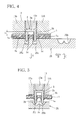
- the crimp pieces 3b are pierced into the conductor 1a with a gap G left between their substrates 3a and flat cable 1. In this way, the crimp pieces 3b are electrically connected to the cut ends 1c of the conductor 1a at contact positions P1, as shown in Fig. 5.
- the urging member 13 and receptacle 25 are detached from the flat cable 1 in the ve r tical direction.
- the receptacle 25 is moved down, as indicated by an arrow A in Fig. 4, by the first elevating press 15 to release the crimp pieces 3b from the pair of receiving grooves 25a. Since the flat cable 1 is held at two points by the chucks 19, the contact positions P1 of the crimp pieces 3b with the conductor 1a are kept unchanged.
- the receptacle 25 is moved horizontally from the position shown in Fig. 3D to place the two bending recesses 25b opposite to the crimp pieces 3b. Specifically, the receptacle 25 is moved horizontally to the left by the switching cylinder 16 as indicated by an arrow B in Fig. 4. In parallel with this, the urging member 13 is moved down to a bottom dead center PL at which the urging tool 13a comes in contact with the substrate 3a.
- the receptacle 25 is moved up from the position shown in Fig. 3E to a top dead center PU. More specifically, the receptacle 25 is moved upward, as indicated by an arrow C in Fig. 4, by the first elevating press 15, while maintaining the contact positions P1 of the crimp pieces 3b to the conductor 1a unchanged.
- the crimp pieces 3b are urged simultaneously by both the urging tool 13a close to the substrate 3a and the bending recesses 25b close to the leading ends of the crimp pieces 3b.
- the leading ends of the crimp pieces 3b are bent while they are curved in an arc shape along the bending recesses 25b.
- an urging force is imparted to the urging tool 13a from the second elevating press 17.
- An urging force for urging the substrate 3a is set to be larger than an urging force with which the receptacle 25 urges the leading ends of the crimp pieces 3b.
- FIG. 3G shows an example of the flat cable 1 to which the connecting terminal 3 is connected in the foregoing manner.
- receptacle 25 may be moved from the state shown in Fig. 3C through the steps of Figs. 3D and 3E to the step of Fig. 3F.
- the flat cable 1 is connected to the connecting terminal 3, as shown in Fig. 7, and a bent portion 3d arcuately curved and formed at the leading end of each crimp piece 3b overlaps the contact position P1 at which the crimp piece 3b is in contact with the cut end 1c of the conductor 1a.
- the flat cable 1 and the connecting terminal 3 are retained in a state where a large contact load is applied to the bent portion 3d and the contact position P1.
- the flat cable 1 is held by the chucks 19 at two points, and the crimp pieces 3b are urged simultaneously from the urging tool piece 13a and from the leading ends of the crimp pieces 3b.
- the flat cable 1 is connected with the connecting terminal 3, while maintaining the contact position P1 of the crimp piece 3b and the cut end 1c unchanged. Therefore, the cut end 1c of the conductor 1a and the crimp piece 3b of the connecting terminal 3 are retained in a state they are applied with a high contact load, thereby providing a stable electric connection between the conductor 1a and crimp piece 3b.
- the crimp pieces 3b are pierced into the conductor 1a until the substrate 3a comes in contact with the flat cable 1, a stable electric connection cannot be provided between the crimp pieces 3b and conductor 1a, even if the subsequent step of bending the leading ends of the crimp pieces 3b is performed in a manner similar to the above. Specifically, as shown in Fig. 8, the bent portion 3e of the crimp piece 3b does not overlap the contact position P2 at which the crimp piece 3b is in contact with the cut end 1c of the conductor 1a. For this reason, a significantly reduction is caused in contact load applied to the conductor 1a and the crimp piece 3b, thus failing to provide a stable electric connection therebetween.
- the bent portion 3e of the crimp piece 3b does not overlap the contact position P2 between the crimp piece 3b and the cut end 1c of the conductor 1a. For this reason, the crimp piece 3b cannot involve the cut end 1c when its leading end is bent, resulting in a reduction in the contact load applied to the conductor 1a and the crimp piece 3b.
- Each flat cable 1 was approximately 0.35 mm in thickness with a conductor 1a of 0.15 mm in thickness and 2.5 mm in width Wc covered with an insulating material formed of a polyethylene terephthalate (PET) film.
- PET polyethylene terephthalate
- Each connecting terminal 3 was provided with crimp pieces 3b of approximately 2.3 mm long arranged on both sides in the width direction of a substrate 3a of 2.0 mm in width Wt.
- the crimp pieces 3b were pierced into the conductor 1a without any gap between the substrate 3a and flat cable 1, and the leading ends of the crimp pieces 3b were arcuately curved.
- a receptacle 27a shown in Fig. 10 is used in place of the receptacles 11, 25.
- the receptacle 27 has a partition 27c formed with a pair of receiving grooves 27a, as shown in Fig. 10.
- the partition 27c is provided with pressurizing incline planes 27d at an entrance of receiving grooves 27a.
- cut ends 1c are formed in a conductor 1a by means of the pressurizing incline planes 27d in cooperation with the crimp pieces 3b pierced into the conductor 1a.
- Each cut end 1c extends along the inner face of the crimp piece 3b and is in contact with the inner face of the crimp piece 3b with a constant contact pressure over substantially the entire length of the cut end.
- the pressurizing incline plane 27d which is continuous to the receiving groove 27a, is formed by chamfering the ridge on the upper edge of the partition 27c into an arcuate surface.
- An inclination angle of the pressurizing incline plane 27d depends on the materials of the crimp piece 3b and conductor 1a, the shape of the crimp pieces 3b, the thickness of the conductor 1a, and the like, and is not uniquely determined.
- the receptacle 27 is used to pierce the crimp pieces 3b of the connecting terminal 3 into a desired conductor 1a of the flat cable 1. Due to the provision of the pressurizing incline planes 27d of the partition of the receptacle 27, the conductor 1a is formed with the cut ends 1c which extend along the inner faces of the crimp pieces 3b, as shown in Fig. 11, and which are in contact therewith over substantially the entire length thereof with a constant contact pressure. For instance, the cut end 1c is in contact with the crimp piece 3b at several points, e.g., three points P3 to P5. Contact pressures at these points P3 to P5 are the same from one another. Therefore, the connecting terminal 3 is connected to the flat cable 1 in a stable state, without causing variations in contact resistance.
- the leading ends of the crimp pieces 3b penetrating the flat cable 1 are released from the receiving grooves 27a, the leading ends are bent and arcuately curved by a bending recess, not shown, while maintaining cut ends 1c in contact with the crimp pieces 3b, whereby the connecting terminal 3 is connected to the flat cable 1.
- the conductor 1a can be connected to the plurality of crimp pieces 3b in a stable state with less variations in contact resistance.
- the connecting apparatus which embodies the connecting method of this embodiment uses the receptacle 27 having the pressurizing incline planes 27d.
- the cut ends 1c formed in the conductor 1a when the crimp pieces 3b are pierced thereinto can be brought into contact with the inner faces of the crimp pieces 3b with a constant contact pressure over substantially the entire length of the cut ends. Therefore, according to this embodiment, it is possible to provide a connecting apparatus for connecting the flat cable to the connecting terminal in a stable connecting state with less variations in contact resistance of the crimp pieces 3b to the conductor 1a.
- the sample S1 was fabricated in accordance with the method of this invention, in which a connecting terminal 3 having a substrate 3a of 2.1 mm in width Wt and a crimp piece 3b of 0.25 mm in thickness was connected to an insulation extruded type flat cable 1 having a conductor 1a of 0.15 mm in thickness and 2.5 mm in width Wc_covered with an insulating material 1b made of a polybuthylene terephthalate film (PBT).
- PBT polybuthylene terephthalate film
- the sample S2 was fabricated by connecting a flat cable 1 to a connecting terminal 3, which were the same kinds as those of sample S1, in accordance with the conventional method modified by shifting a position, at which a crimp piece 3b was pierced, from the center of the receiving groove 27a in the width direction of the groove.
- the sample S3 was fabricated by piercing the crimp pieces 3b into a flat cable 1 using a conventional receptacle other than the receptacle 27.
- Fig. 12 The result of the test is shown in Fig. 12.
- the use of the receptacle 27 is essential in the connecting method and the connecting apparatus 10 of this embodiment in order to provide a stable connecting state with less variations in contact resistance.
- the sample S1 connected using the receptacle 27 shows a stable connecting state with less variations in contact resistance than the sample S2 based on the conventional method.
- the sample S1 uses the insulation extruded type flat cable 1, it shows stable performance, with less variations in contact resistance, equivalent or superior to the conventional flat cable which uses a polyethylene terephthalate (PET) film as the insulating material 1b.
- PET polyethylene terephthalate
- the connecting state of the conductor 1a to the crimp piece 5b when the flat cable 1 is connected to the connecting terminal 5 largely depends on a contact load (N) with which the cut end 1c of the conductor 1a is in contact with the crimp piece 5b.
- pass/fail of the connecting state of the conductor 1a to the crimp piece 5b largely depends on a resistive load (N) observed after through-holes extending through the conductor 1a are formed by piercing the crimp pieces 5b into the flat cable 1.
- the connecting apparatus 20 is configured to create a load change characteristic diagram when the crimp pieces 5b are pierced into the flat cable 1, with the horizontal axis representing a displacement amount (mm) of the crimp pieces and the vertical axis representing the load (N) acting on the crimp pieces, based on electric signals related to a load and a displacement amount input from the load cell 17b of the second elevating press 17 and the displacement mount sensor 18.
- a load acting on the crimp pieces increases to a maximum load L1 required for the crimp pieces 5b to penetrate through the entire flat cable 1, and then decreases to a minimum load L3 which corresponds to a friction resistance between the crimp pieces 5b and the conductor 1a.
- a difference L2 between the maximum load L1 and the load varying depending on the displacement of the crimp pieces represents a piercing load, i.e., a load of a resistance associated with the formation of openings in the conductor 1a by means of the crimp pieces 5b.
- a thermal shock test for a flat cable connected with a connecting terminal reveals that the crimp pieces 5b can be connected to the conductor 1a under a stable contact load when the piercing load L2 has a value equal to or less than a buckle threshold value of the crimp pieces 5b.
- a relative position of a conductor 1a and a crimp piece 5b of a connecting terminal 5 changes.
- a relative position K1 is assumed, an opening H1 having a width of 2t1 is formed in the conductor 1a.
- the connecting terminal 5 is further moved down, the width of the opening in the conductor gradually increases.
- an opening H2 having a width of 2(t1+t2) is formed.
- the width 2(t1+t2) of the opening is kept unchanged although the connecting terminal 5 is further moved downward.
- Symbol K2 denotes, by way of example, a relative position of the conductor 1a and the crimp piece 5b after the tapered portion passes through the conductor.
- the piercing load L2 is determined and compared with a normal piercing load serving as the criteria to determine a connecting state.
- the normal piercing load which is determined in advance during the fabrication of non-defective products, varies in a range from 150N to 220N, for instance.
- pass/fail of a connecting state is determined by making a determination as to whether or not the piercing load L2 determined during the actual connecting operation falls with in a range, e.g., from 150N to 220N.
- Fig. 15 is a load change characteristic diagram of a measured piercing load to a displacement amount of the crimp pieces 5b in a variety of samples S4 to S7.
- the sample S4 is an actually measured result in the normal state described in connection with Fig. 13, where the piercing load L21 is approximately 180N.
- the sample S6 is an actually measured result when a residue of the insulating material 1b or foreign substances clog between the receiving grooves 11a and flat cable 1 to cause an abnormally large contact load between the crimp pieces 5b and the cut end 1c of the conductor 1a.
- the sample S7 is an actually measured result when the crimp pieces 5b cannot penetrate the flat cable 1 and are buckled due to foreign substances introduced into the receiving grooves 11a, defective receiving grooves 11a, defective thicknesses of the conductor 1a and insulating material 1b, and the like.
Landscapes
- Engineering & Computer Science (AREA)
- Manufacturing & Machinery (AREA)
- Coupling Device And Connection With Printed Circuit (AREA)
- Multi-Conductor Connections (AREA)
Abstract
Description
- The sample S5 is an actually measured result in a
defective state, where the piercing load is L22. Here, the
defective state may be, for example, the
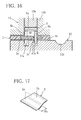
crimp pieces 5b not properly inserted into the receivinggrooves 11a, or thecrimp pieces 5b pierced into theflat cable 1 with a gap g betweencrimp pieces 5b and partition 11c larger than normal, as shown in Fig. 16. When the gap g is larger than normal, a contact load between thecut end 1c of the conductor 1a and thecrimp piece 5b is reduced.
- While the connecting state determining method of this
embodiment has been described in connection with the
connecting
terminal 5, a similar determination can be made as well when the connectingterminal 3 is used.
Claims (13)
- A method of connecting a flat cable to a connecting terminal, in which the flat cable having a plurality of flat conductors, arranged in parallel and having surfaces thereof covered with an insulating material, is connected to the connecting terminal, by piercing a plurality of crimp pieces, formed integrally with a substrate of the connecting terminal, into a desired conductor of the flat cable and by inwardly bending leading ends of the crimp pieces penetrating the flat cable to hold the desired conductor therebetween, comprising the steps of:piercing the crimp pieces into the desired conductor with a gap left between the substrate and the flat cable; andbending the leading ends of the crimp pieces while maintaining a contact position unchanged at which each of the crimp pieces penetrating the conductor is in contact with the conductor.
- The method according to claim 1, wherein the crimp pieces are urged simultaneously from the substrate and from the leading ends of the crimp pieces when the leading ends are bent.
- The method according to claim 1, wherein an urging force for urging the substrate is set to be larger than an urging force for urging the leading ends of the crimp pieces.
- A method of connecting a flat cable to a connecting terminal, in which the flat cable, having a plurality of flat conductors arranged in parallel and having surfaces thereof covered with an insulating material, is connected to the connecting terminal, by piercing a plurality of crimp pieces, formed integrally with a substrate of the connecting terminal, into a desired conductor of the flat cable and by inwardly bending leading ends of the crimp pieces penetrating the flat cable to hold the desired conductor therebetween, comprising the step of:forming cut ends in the desired conductor by means of the plurality of crimp pieces pierced into the desired conductor, each cut end extending along an inner face of a corresponding one crimp piece and in contact with the inner face with a constant contact pressure over substantially the entire length of the cut end.
- A method of connecting a flat cable to a connecting terminal, in which the flat cable, having a plurality of flat conductors arranged in parallel and having surfaces thereof covered with an insulating material, is connected to the connecting terminal, by piercing a plurality of crimp pieces, formed integrally with a substrate of the connecting terminal, into a desired conductor of the flat cable and by inwardly bending leading ends of the crimp pieces penetrating the flat cable to hold the desired conductor therebetween, comprising the steps of:forming cut ends in the desired conductor by means of the plurality of crimp pieces pierced into the desired conductor, each cut end extending along an inner face of a corresponding one crimp piece and in contact with the inner face with a constant pressure over substantially the entire length of the cut end; andinwardly bending the leading ends of the crimp pieces penetrating the flat cable, while maintaining a contact state of the cut ends with the crimp pieces unchanged.
- A connecting apparatus for connecting a flat cable to a connecting terminal, in which the connecting apparatus connects a flat cable having a plurality of flat conductors arranged in parallel and having surfaces covered with an insulating material to a connecting terminal by piercing a plurality of crimp pieces, formed integrally with a substrate of the connecting terminal, into a desired conductor of the flat cable, and by inwardly bending leading ends of the crimp pieces penetrating the flat cable to hold the desired conductor therebetween, comprising:a receptacle on which the flat cable held at a predetermined position is placed, the receptacle having a pair of receiving grooves for receiving the crimp pieces, and a bending recess for bending the leading ends of the crimp pieces;an urging member having an urging tool, disposed opposite the receptacle with the flat cable interposed therebetween, for urging the substrate of the connecting terminal, and a guide member for guiding movements of the urging tool;first driving means having elevating means for moving the receptacle up and down, and a moving means for moving the receptacle to selectively place the receiving groove or the bending recess of the receptacle to opposite the connecting terminal;second driving means for urging the urging tool toward the substrate; andcontrol means for controlling the operation of the connecting apparatus.
- The connecting apparatus according to claim 6, wherein the receptacle has a partition formed with the pair of receiving grooves, and the partition comprises a pressurizing incline plane at an entrance of each of the receiving grooves for forming cut ends in the desired conductor by means of the crimp pieces pierced into the desired conductor, each cut end extending along an inner face of a corresponding one crimp piece and in contact with the inner face with a constant contact pressure over substantially the entire length of the cut end.
- The connecting apparatus according to claim 6, wherein the urging member comprises a first sensor for detecting a load acting on the crimp pieces when the substrate is urged by the urging tool to pierce the crimp pieces into the flat cable, and a second sensor for detecting a displacement amount of the crimp pieces with a movement of the urging tool, wherein information detected by both the sensors is output to the control means.
- The connecting apparatus according to claim 6, wherein the control means receives load information from the first sensor and displacement amount information from the second sensor, and determines a connecting state of the crimp pieces to the conductor when the flat cable is connected to the connecting terminal.
- The connecting apparatus according to claim 6, wherein the receptacle comprises a top dead center position adjusting mechanism for adjusting a top dead center position of the receptacle.
- The connecting apparatus according to claim 6, wherein the urging member comprises a bottom dead center position adjusting mechanism for adjusting a bottom dead center position of the urging tool.
- A connecting state determining method for determining a connecting state of a connecting terminal to a flat cable having a plurality of flat conductors arranged in parallel and having surfaces thereof covered with an insulating material, in which the connecting state is determined when a desired conductor of the flat cable is connected to the connecting terminal by piercing a plurality of crimp pieces formed integrally with a substrate of the connecting terminal into the desired conductor and by inwardly bending leading ends of the crimp pieces penetrating the flat cable to hold the desired conductor therebetween, comprising the step of:determining the connecting state of the crimp pieces to the desired conductor by comparing a piercing load determined when the crimp pieces are pierced into the flat cable and a normal piercing load determined in advance and observed when crimp pieces are normally pierced into a flat cable.
- The connecting state determining method according to claim 12, wherein the piercing load is determined based on a difference between a maximum load and a minimum load acting on the crimp pieces measured when the crimp pieces are pierced into the flat cable, the minimum load being measured after the maximum load is reached.
Priority Applications (1)
| Application Number | Priority Date | Filing Date | Title |
|---|---|---|---|
| EP08169131A EP2023450B1 (en) | 2001-05-21 | 2002-05-07 | Method of connecting flat cable to connecting terminal |
Applications Claiming Priority (6)
| Application Number | Priority Date | Filing Date | Title |
|---|---|---|---|
| JP2001151338A JP4030275B2 (en) | 2001-05-21 | 2001-05-21 | Connection failure detection method when connecting the flat cable to the connection terminal |
| JP2001151338 | 2001-05-21 | ||
| JP2001320855A JP4205328B2 (en) | 2001-10-18 | 2001-10-18 | How to connect the flat cable to the connection terminal |
| JP2001320855 | 2001-10-18 | ||
| JP2001344930A JP4234336B2 (en) | 2001-11-09 | 2001-11-09 | Connection method and connection device between flat cable and connection terminal |
| JP2001344930 | 2001-11-09 |
Related Child Applications (2)
| Application Number | Title | Priority Date | Filing Date |
|---|---|---|---|
| EP08169131A Division EP2023450B1 (en) | 2001-05-21 | 2002-05-07 | Method of connecting flat cable to connecting terminal |
| EP08169131.3 Division-Into | 2008-11-14 |
Publications (3)
| Publication Number | Publication Date |
|---|---|
| EP1261081A2 true EP1261081A2 (en) | 2002-11-27 |
| EP1261081A3 EP1261081A3 (en) | 2008-01-02 |
| EP1261081B1 EP1261081B1 (en) | 2010-03-17 |
Family
ID=27346760
Family Applications (2)
| Application Number | Title | Priority Date | Filing Date |
|---|---|---|---|
| EP08169131A Expired - Lifetime EP2023450B1 (en) | 2001-05-21 | 2002-05-07 | Method of connecting flat cable to connecting terminal |
| EP02009389A Expired - Lifetime EP1261081B1 (en) | 2001-05-21 | 2002-05-07 | Method for assembling for flat cable connector and determining its connecting state |
Family Applications Before (1)
| Application Number | Title | Priority Date | Filing Date |
|---|---|---|---|
| EP08169131A Expired - Lifetime EP2023450B1 (en) | 2001-05-21 | 2002-05-07 | Method of connecting flat cable to connecting terminal |
Country Status (3)
| Country | Link |
|---|---|
| US (2) | US6722034B2 (en) |
| EP (2) | EP2023450B1 (en) |
| DE (1) | DE60235673D1 (en) |
Cited By (2)
| Publication number | Priority date | Publication date | Assignee | Title |
|---|---|---|---|---|
| US6722034B2 (en) * | 2001-05-21 | 2004-04-20 | The Furukawa Electric Co., Ltd. | Method of connecting cable to connector |
| WO2009117789A3 (en) * | 2008-03-25 | 2009-11-12 | Föhrenbach Application Tooling N.V. | Method and installation to fit out flexible films equipped with electric conductors |
Families Citing this family (10)
| Publication number | Priority date | Publication date | Assignee | Title |
|---|---|---|---|---|
| JP3870880B2 (en) * | 2002-09-04 | 2007-01-24 | 住友電装株式会社 | Connection structure between conductor and pressure contact terminal |
| JP4839014B2 (en) * | 2005-04-07 | 2011-12-14 | 矢崎総業株式会社 | Manufacturing method of flat circuit body with terminal fitting, manufacturing mold of flat circuit body with terminal fitting, and manufacturing apparatus of flat circuit body with terminal fitting |
| JP4668687B2 (en) * | 2005-05-27 | 2011-04-13 | 矢崎総業株式会社 | Piercing terminal, connection structure between flat circuit body and piercing terminal, and connection method between flat circuit body and piercing terminal |
| JP4464891B2 (en) * | 2005-08-30 | 2010-05-19 | 矢崎総業株式会社 | Terminal connection device |
| JP4568210B2 (en) * | 2005-11-14 | 2010-10-27 | 矢崎総業株式会社 | Terminal metal fittings and flat circuit body with terminals |
| JP4500254B2 (en) * | 2005-12-26 | 2010-07-14 | 矢崎総業株式会社 | Flat circuit body |
| GB201204866D0 (en) * | 2012-03-20 | 2012-05-02 | Trw Ltd | Fork type electrical connector |
| US9799965B2 (en) * | 2014-05-17 | 2017-10-24 | Igor Ofenbakh | System for coupling a conductive substrate to a ribbon cable |
| US20230023483A1 (en) * | 2022-09-27 | 2023-01-26 | Intel Corporation | Methods and apparatus to enable customization of pigtail lengths of optical connectors |
| US12347983B2 (en) | 2022-11-30 | 2025-07-01 | Lear Corporation | Connector for an electrical terminal with a crimped spring |
Family Cites Families (11)
| Publication number | Priority date | Publication date | Assignee | Title |
|---|---|---|---|---|
| US3697925A (en) * | 1970-07-22 | 1972-10-10 | Amp Inc | Termination means for flat cable |
| US3924917A (en) * | 1974-04-30 | 1975-12-09 | Elco Corp | Flat cable termination method and apparatus |
| US4831722A (en) * | 1981-10-26 | 1989-05-23 | Burndy Corporation | Apparatus and method for installing electrical connectors on flat conductor cable |
| US4669798A (en) * | 1986-01-09 | 1987-06-02 | General Motors Corporation | Electrical terminal for flexible printed circuits |
| JPS63281071A (en) | 1987-05-13 | 1988-11-17 | Furukawa Electric Co Ltd:The | Detecting method for defect in terminal crimping of terminal-crimped electric conductor |
| JPS6444780A (en) | 1987-08-12 | 1989-02-17 | Hakobu Kunimori | Transfer printing method |
| JP3708287B2 (en) * | 1996-05-23 | 2005-10-19 | 株式会社オートネットワーク技術研究所 | Pressure welding of electric wires in the production of automotive wire harnesses |
| JP3756938B2 (en) | 1997-11-13 | 2006-03-22 | 古河電気工業株式会社 | Electrical connection terminal |
| JP2002184548A (en) * | 2000-12-12 | 2002-06-28 | Furukawa Electric Co Ltd:The | Conductive connection method between flat cable and electrical connector |
| EP2023450B1 (en) * | 2001-05-21 | 2012-07-18 | The Furukawa Electric Co., Ltd. | Method of connecting flat cable to connecting terminal |
| JP2003187892A (en) * | 2001-12-19 | 2003-07-04 | Yazaki Corp | Connecting member for flat circuit body and method for connecting the connecting member to flat circuit body |
-
2002
- 2002-05-07 EP EP08169131A patent/EP2023450B1/en not_active Expired - Lifetime
- 2002-05-07 DE DE60235673T patent/DE60235673D1/en not_active Expired - Lifetime
- 2002-05-07 EP EP02009389A patent/EP1261081B1/en not_active Expired - Lifetime
- 2002-05-08 US US10/142,528 patent/US6722034B2/en not_active Expired - Lifetime
-
2003
- 2003-09-25 US US10/673,015 patent/US6869305B2/en not_active Expired - Lifetime
Cited By (4)
| Publication number | Priority date | Publication date | Assignee | Title |
|---|---|---|---|---|
| US6722034B2 (en) * | 2001-05-21 | 2004-04-20 | The Furukawa Electric Co., Ltd. | Method of connecting cable to connector |
| US6869305B2 (en) | 2001-05-21 | 2005-03-22 | The Furukawa Electric Co., Ltd. | Method of connecting flat cable to connecting terminal, connecting apparatus, and connecting state determining method |
| WO2009117789A3 (en) * | 2008-03-25 | 2009-11-12 | Föhrenbach Application Tooling N.V. | Method and installation to fit out flexible films equipped with electric conductors |
| BE1018064A3 (en) * | 2008-03-25 | 2010-04-06 | Fihrenbach Applic Tooling N V | WERKWIJZE IN INRICHTING VOOR HET BESTUKKEN VAN FLEXIBLELE FOLIES VOORZIEN VAN ELEKTRISCHE GELEIDERS. |
Also Published As
| Publication number | Publication date |
|---|---|
| US20040063351A1 (en) | 2004-04-01 |
| DE60235673D1 (en) | 2010-04-29 |
| EP2023450B1 (en) | 2012-07-18 |
| EP1261081A3 (en) | 2008-01-02 |
| US20020173196A1 (en) | 2002-11-21 |
| US6869305B2 (en) | 2005-03-22 |
| EP1261081B1 (en) | 2010-03-17 |
| EP2023450A1 (en) | 2009-02-11 |
| US6722034B2 (en) | 2004-04-20 |
Similar Documents
| Publication | Publication Date | Title |
|---|---|---|
| EP1261081B1 (en) | Method for assembling for flat cable connector and determining its connecting state | |
| US7581979B2 (en) | Flat circuit device | |
| US7927122B2 (en) | Connector assembly having an improved connection mechanism | |
| CN1099727C (en) | Electrical connector for printed circuit boards | |
| US7775842B2 (en) | Crimping structure and crimping method | |
| JP4898463B2 (en) | Terminal crimping apparatus and terminal crimping method | |
| CN106129726A (en) | Electrically shielded connector | |
| GB2377830A (en) | Crimp contact | |
| US11152718B2 (en) | Electrical cable including terminal having pressing portion that presses holding portion | |
| US6193138B1 (en) | Pressure welding device and method for terminals | |
| US7513792B2 (en) | Chained-terminals body, method of manufacturing the same, and crimper for crimping the same | |
| US7264498B2 (en) | Flat harness with a cut conductor, and manufacturing method thereof | |
| US12191616B2 (en) | Wiring chamber with multiple terminations | |
| US11600937B2 (en) | Electrical terminal for flat flexible cables | |
| CN101449428A (en) | relay connector | |
| CN109428231B (en) | Electrical connector | |
| US6540544B1 (en) | Press-connecting connector and wire press-fitting apparatus | |
| JP2003086323A (en) | How to make insulation cut connection | |
| KR20130058040A (en) | Connector structure | |
| US7448128B2 (en) | Terminal connecting apparatus | |
| US7252535B2 (en) | Flat circuit body with terminals, method of manufacturing the same, die system for manufacturing the same and manufacturing apparatus for the same | |
| JP3708287B2 (en) | Pressure welding of electric wires in the production of automotive wire harnesses | |
| EP0038882B1 (en) | Method of establishing an electrical connection to a conductor on a substrate | |
| US11677167B2 (en) | Electric wire with terminal and terminal crimping device | |
| EP1037315B1 (en) | Connector with contact |
Legal Events
| Date | Code | Title | Description |
|---|---|---|---|
| PUAI | Public reference made under article 153(3) epc to a published international application that has entered the european phase |
Free format text: ORIGINAL CODE: 0009012 |
|
| AK | Designated contracting states |
Kind code of ref document: A2 Designated state(s): AT BE CH CY DE DK ES FI FR GB GR IE IT LI LU MC NL PT SE TR |
|
| AX | Request for extension of the european patent |
Free format text: AL;LT;LV;MK;RO;SI |
|
| PUAL | Search report despatched |
Free format text: ORIGINAL CODE: 0009013 |
|
| AK | Designated contracting states |
Kind code of ref document: A3 Designated state(s): AT BE CH CY DE DK ES FI FR GB GR IE IT LI LU MC NL PT SE TR |
|
| AX | Request for extension of the european patent |
Extension state: AL LT LV MK RO SI |
|
| 17P | Request for examination filed |
Effective date: 20080228 |
|
| 17Q | First examination report despatched |
Effective date: 20080528 |
|
| AKX | Designation fees paid |
Designated state(s): DE FR GB |
|
| GRAP | Despatch of communication of intention to grant a patent |
Free format text: ORIGINAL CODE: EPIDOSNIGR1 |
|
| GRAS | Grant fee paid |
Free format text: ORIGINAL CODE: EPIDOSNIGR3 |
|
| GRAA | (expected) grant |
Free format text: ORIGINAL CODE: 0009210 |
|
| AK | Designated contracting states |
Kind code of ref document: B1 Designated state(s): DE FR GB |
|
| REG | Reference to a national code |
Ref country code: GB Ref legal event code: FG4D |
|
| REF | Corresponds to: |
Ref document number: 60235673 Country of ref document: DE Date of ref document: 20100429 Kind code of ref document: P |
|
| PLBE | No opposition filed within time limit |
Free format text: ORIGINAL CODE: 0009261 |
|
| STAA | Information on the status of an ep patent application or granted ep patent |
Free format text: STATUS: NO OPPOSITION FILED WITHIN TIME LIMIT |
|
| 26N | No opposition filed |
Effective date: 20101220 |
|
| REG | Reference to a national code |
Ref country code: FR Ref legal event code: PLFP Year of fee payment: 15 |
|
| REG | Reference to a national code |
Ref country code: FR Ref legal event code: PLFP Year of fee payment: 16 |
|
| REG | Reference to a national code |
Ref country code: FR Ref legal event code: PLFP Year of fee payment: 17 |
|
| PGFP | Annual fee paid to national office [announced via postgrant information from national office to epo] |
Ref country code: FR Payment date: 20210412 Year of fee payment: 20 Ref country code: DE Payment date: 20210413 Year of fee payment: 20 |
|
| PGFP | Annual fee paid to national office [announced via postgrant information from national office to epo] |
Ref country code: GB Payment date: 20210414 Year of fee payment: 20 |
|
| REG | Reference to a national code |
Ref country code: DE Ref legal event code: R071 Ref document number: 60235673 Country of ref document: DE |
|
| REG | Reference to a national code |
Ref country code: GB Ref legal event code: PE20 Expiry date: 20220506 |
|
| PG25 | Lapsed in a contracting state [announced via postgrant information from national office to epo] |
Ref country code: GB Free format text: LAPSE BECAUSE OF EXPIRATION OF PROTECTION Effective date: 20220506 |